Output Devices
Tools
1.-end mill 1/64'
electronics components
2.-thermistors
3.-DC Motor
4.-pinheader 2x3
5.-pinheader 1x6
6.-1uF capacitor
7.-0.1uF capacitor
8.- A4952
SOFTWARE
9.-xilinx ISE 14.1
10.-fabmodules
MACHINES
11.-Roland Modela
OTHERS
12.-USB JTAG
13.-FPGA-spartan 3
Tools
1.-end mill 1/64'
electronics components
2.-thermistors
3.-DC Motor
4.-pinheader 2x3
5.-pinheader 1x6
6.-1uF capacitor
7.-0.1uF capacitor
8.- A4952
SOFTWARE
9.-xilinx ISE 14.1
10.-fabmodules
MACHINES
11.-Roland Modela
OTHERS
12.-USB JTAG
13.-FPGA-spartan 3
Tools
1.-end mill 1/64'
electronics components
2.-thermistors
3.-DC Motor
4.-pinheader 2x3
5.-pinheader 1x6
6.-1uF capacitor
7.-0.1uF capacitor
8.- A4952
SOFTWARE
9.-xilinx ISE 14.1
10.-fabmodules
MACHINES
11.-Roland Modela
OTHERS
12.-USB JTAG
13.-FPGA-spartan 3
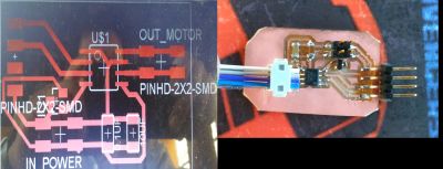
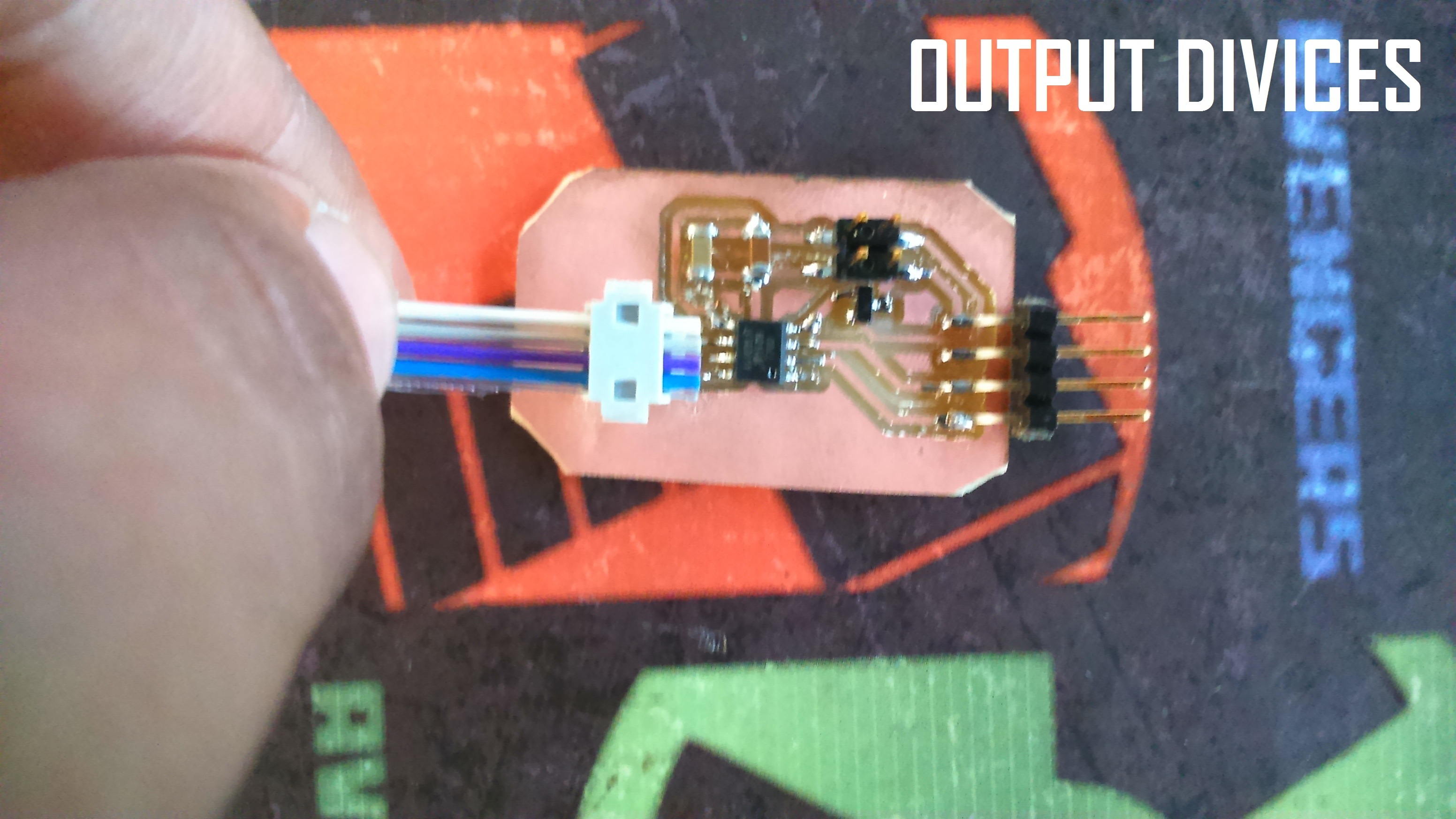
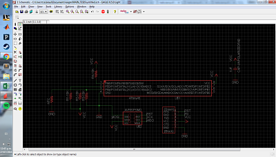
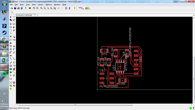
for this assignment, I made a module motor dc circuit dirver (H-bridge eagle SCH AND BRD).in the image you can see the PCB circuit and the final circuit
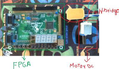
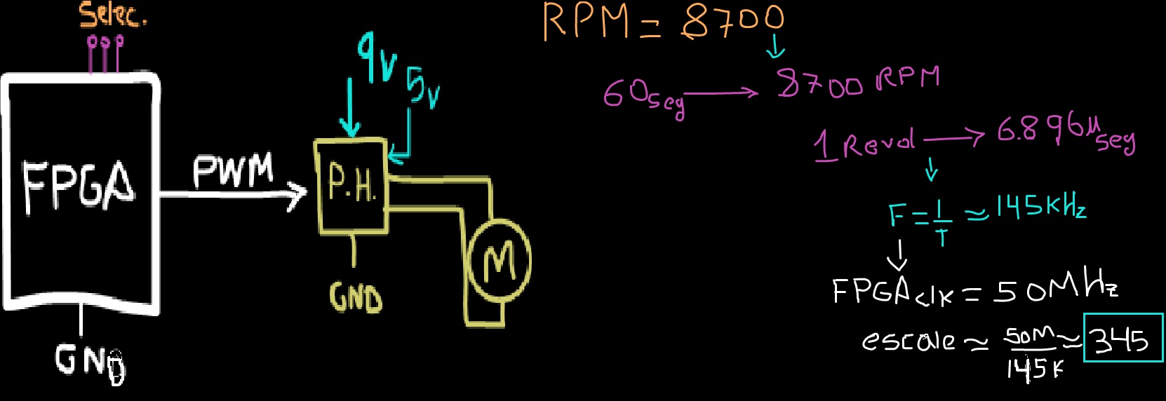
I make a VHDL code on XILINX ISE, beacouse I want to implement a PWM signal for controling the speed of a DC motor , I can implement this on microcontrolers but FPGA is more easier and flexible for make this kind of signal