Electronics Design
Electronics Components
1.-Attiny 44A
2.-diode LED (1206smd)X5
3.-RES 10K Ohm
4.-RES 499 ohms
5.-cap 1uF
6.-oscilator 20MHz
7.-pinheader 2x3
8.- pinheader 1x6
SOFTWARE
3.- eagle
4.-Fabmodule
MACHINES
5.-ROland Modela
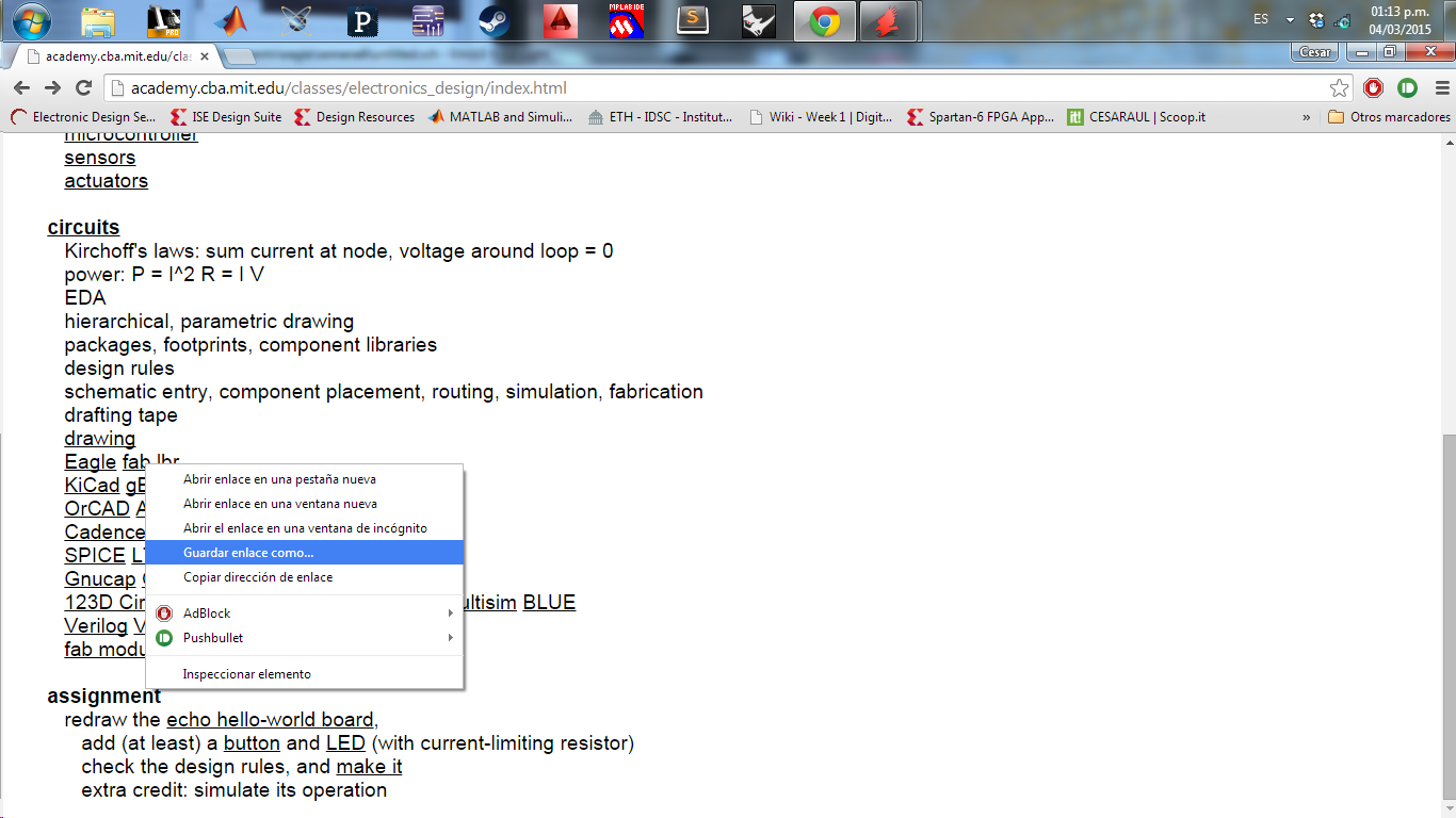
to begin download and save the FAB library for eagle, which contains electronic components that I will use
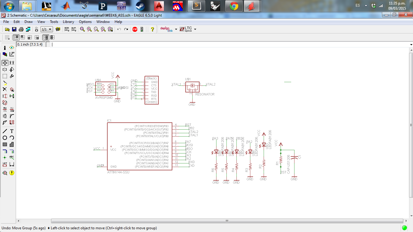
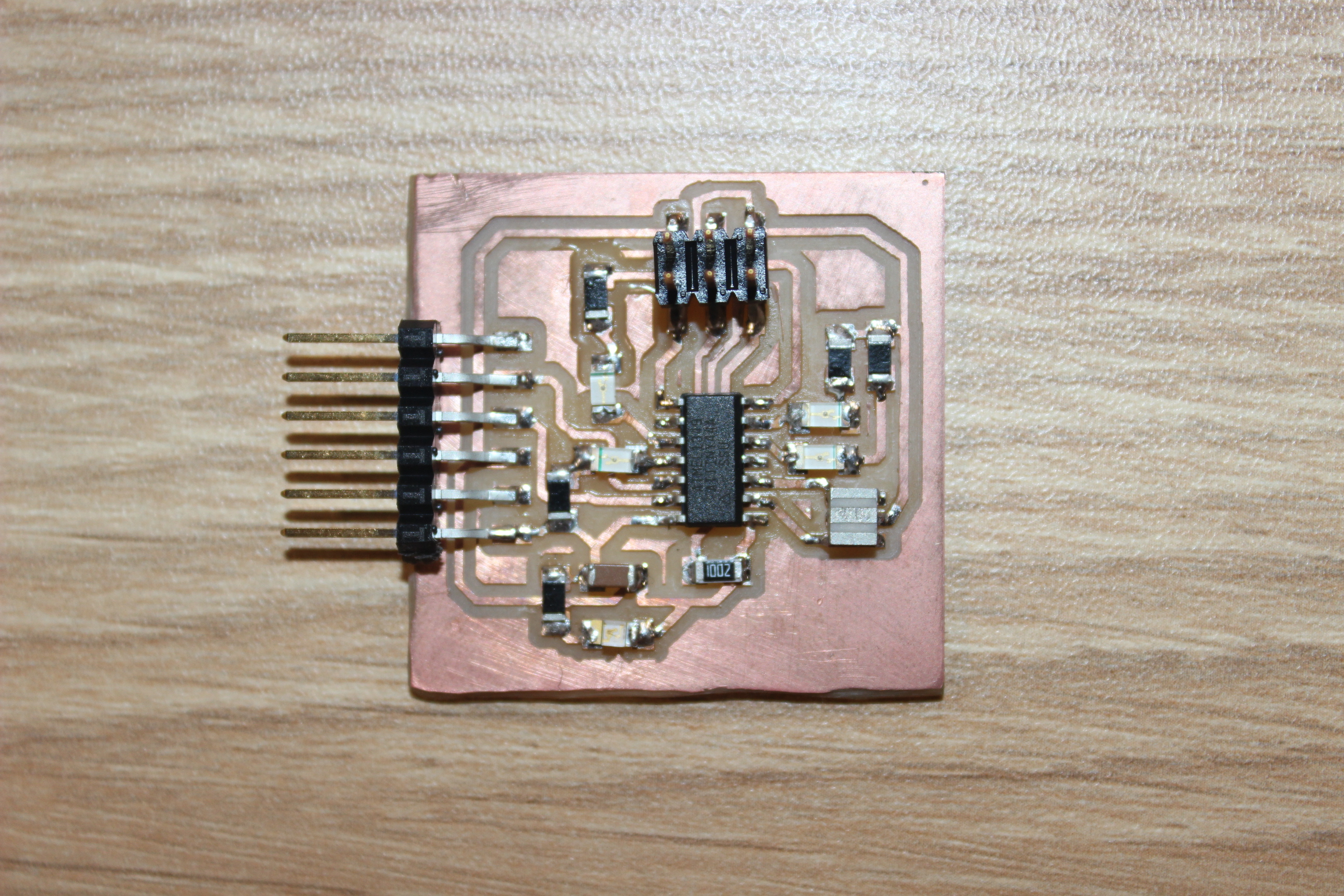
Interconnect components based on the main circuit model, additional mind to the base model, add 4 LED diodes to use on these aplicasiones and adiocinalmente a diode BLUE LED to indicate power on plate
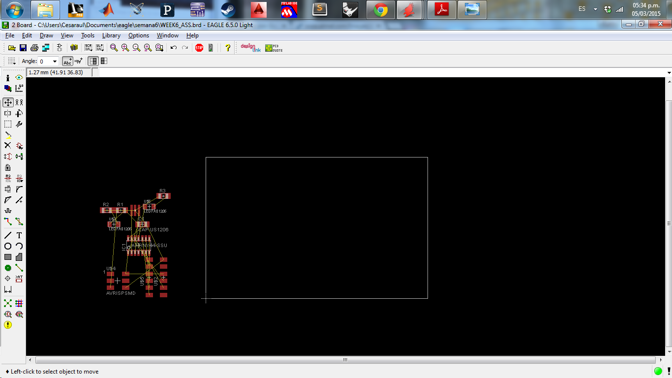
after having the schematic design, generated a BRD file where the PCB vias is built on the schematic
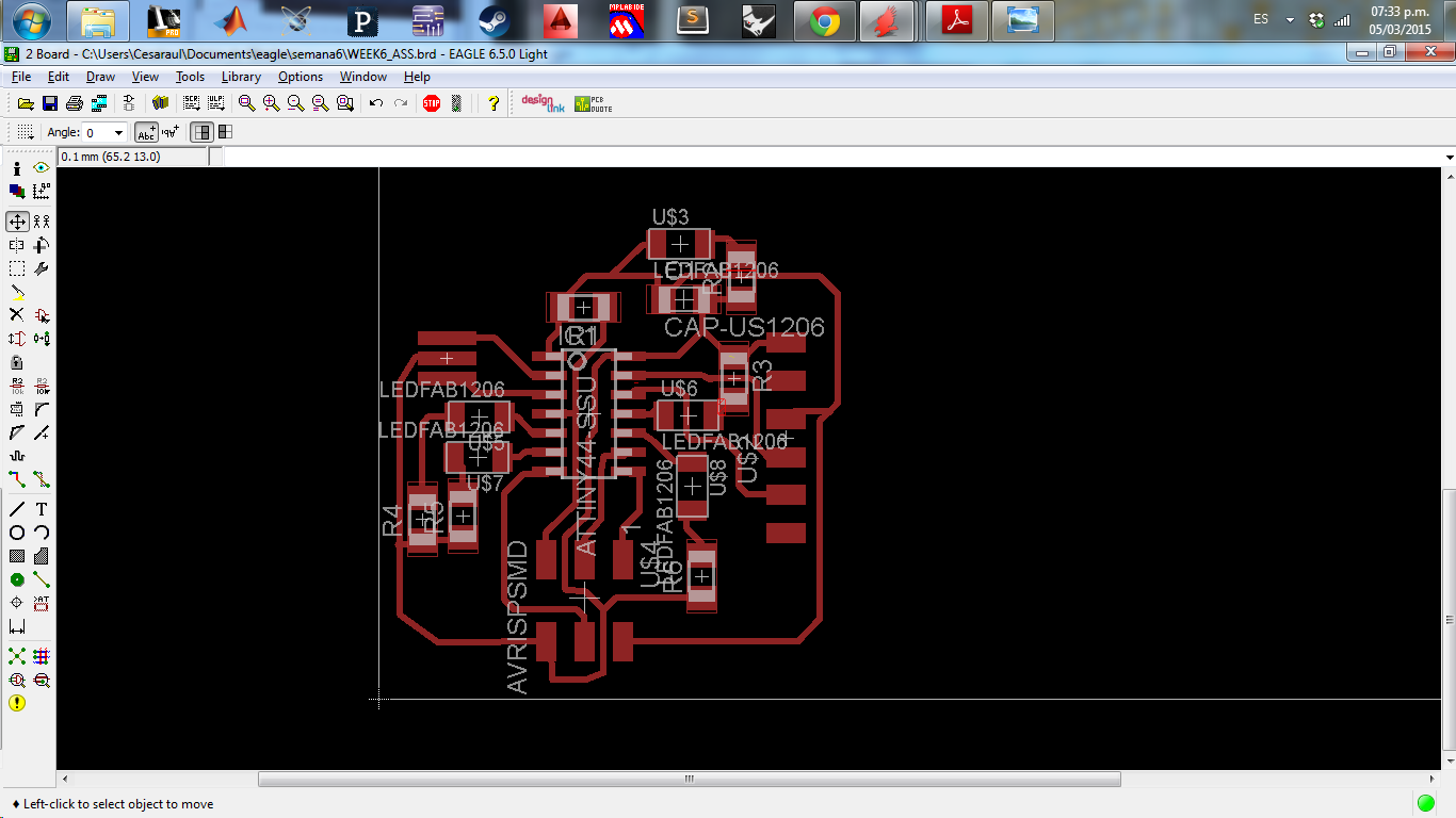
pathways graph plate only in TOP layer, in this case the recommendation is to keep as close as possible to the IC oscillator
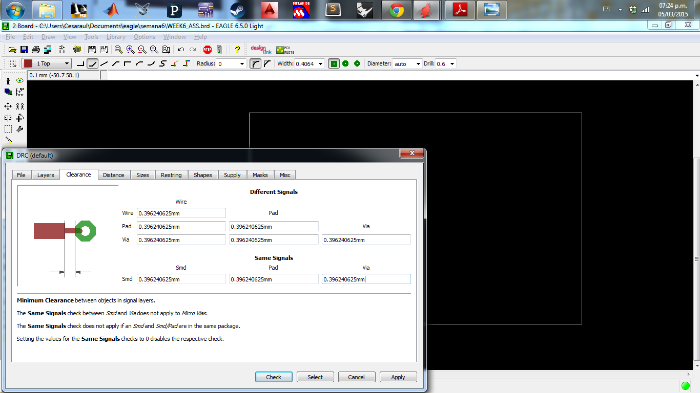
Another important point when plotting the vias is the distance to be maintained between vias to determine this we do ditancia from Strawberry far we will use in this case 1/64 inch to mm transforming this is 0.396875 mm take this measure reference and evaluated using the DRC eagle tool, so it is ready to export the file
Electronics production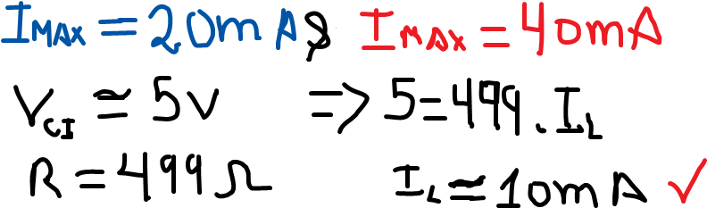
to design the schematic circuit resistance values of the LEDs is not considered, but before welding is necessary to know the suitable value that will be used for this purpose we use Ohm's law V = IR; image current values blue and red LED Imax Imax shown (which will be used ledazul y ledrojo) adalso this integrated voltage VCI (approx) circuit; in this case assumes a 499 ohm R according to the inventory of the FabLab and according to the obtained values are in the current range of both leds
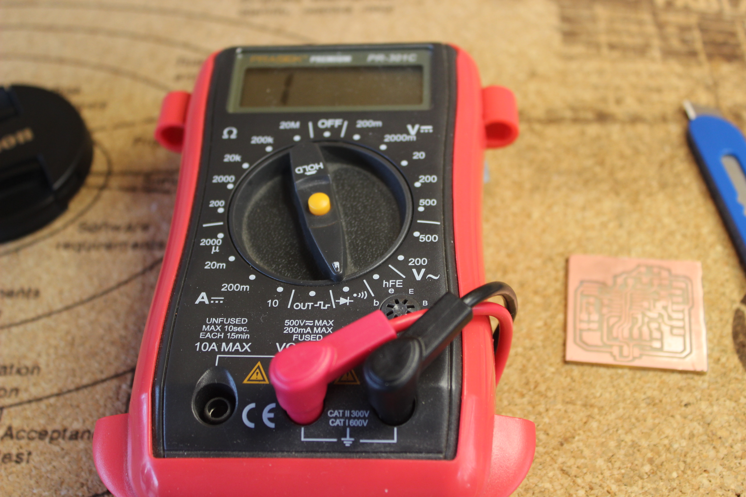
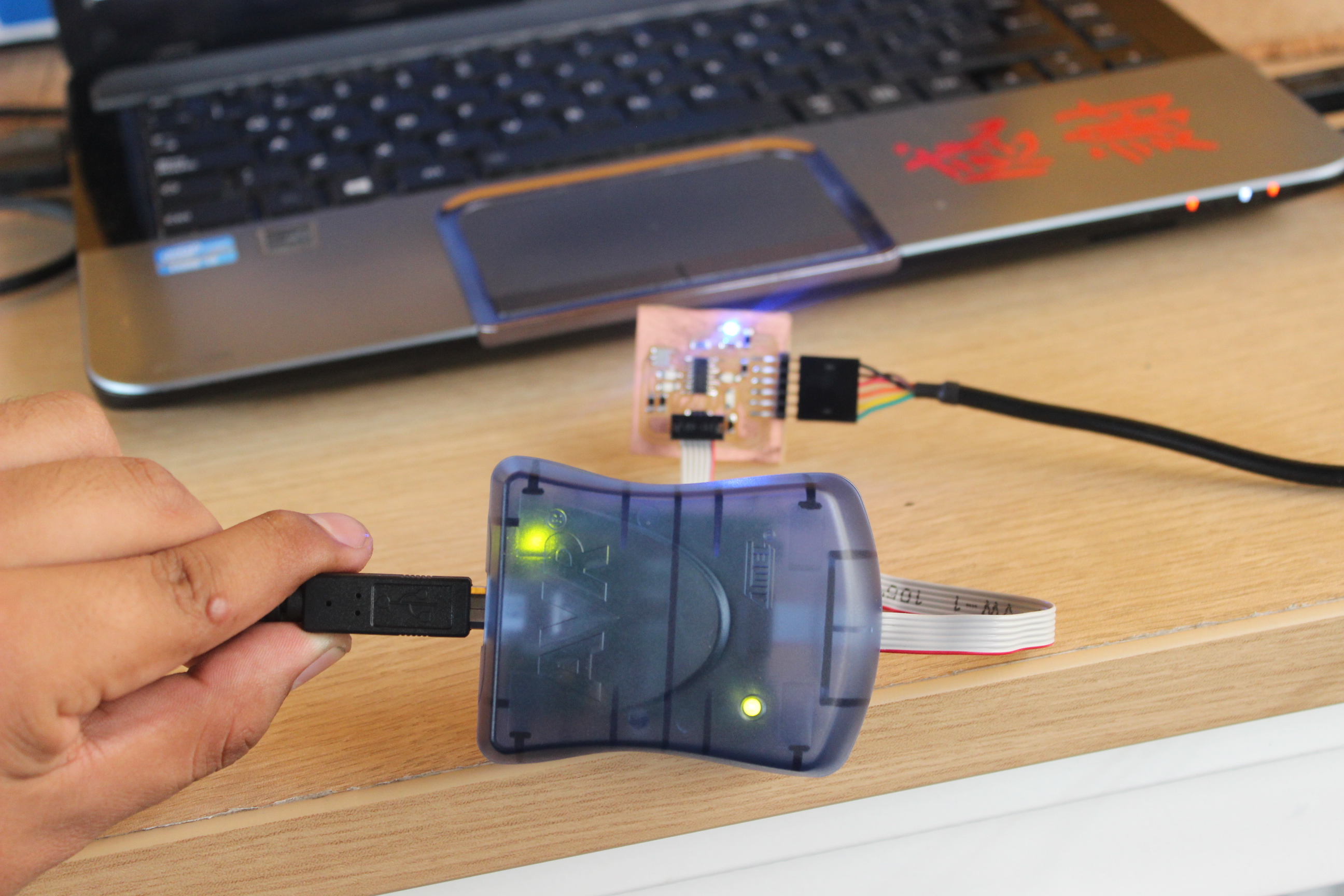
The first step to verify board is using the multimeter tracks and continuity of these are verified, such recommendation is that this revicion the constant mind when they are made by welding and finish an overview nothing more