Final Project
Index
Discarded idea- Reference links
- The idea
- First iteration
- Iteration 1.5, electronics
- Iteration 2
- Iteration 3
- Iteration 4
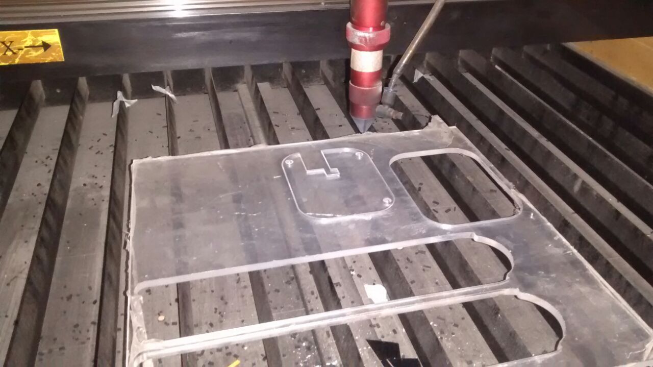
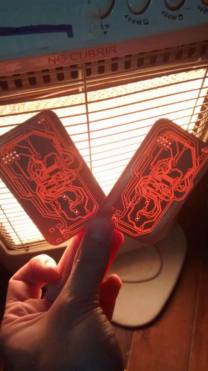
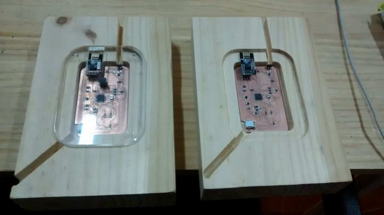
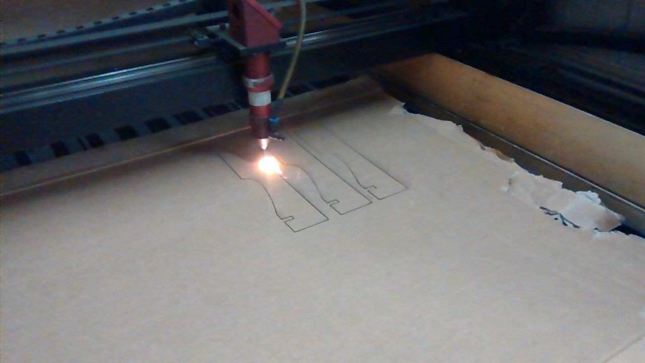
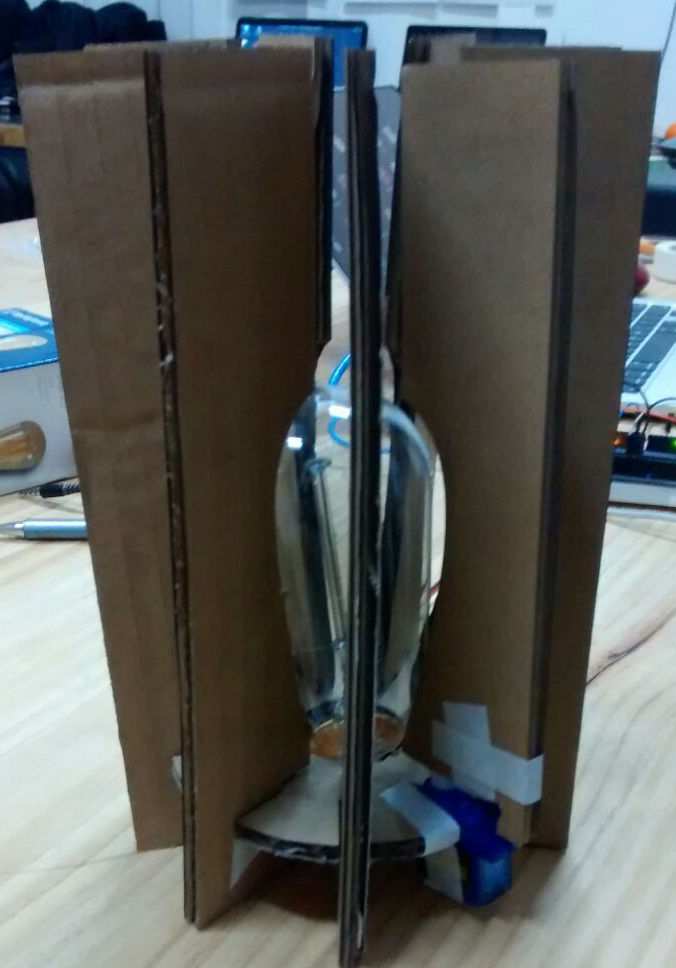
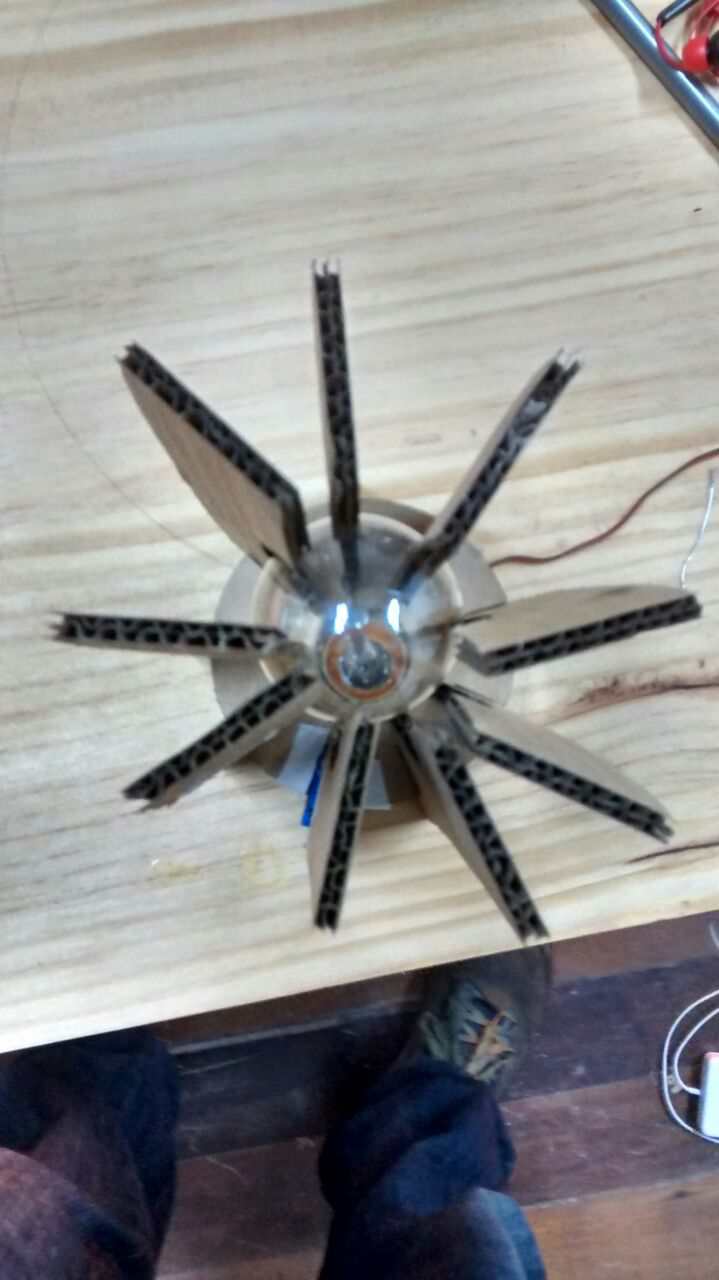
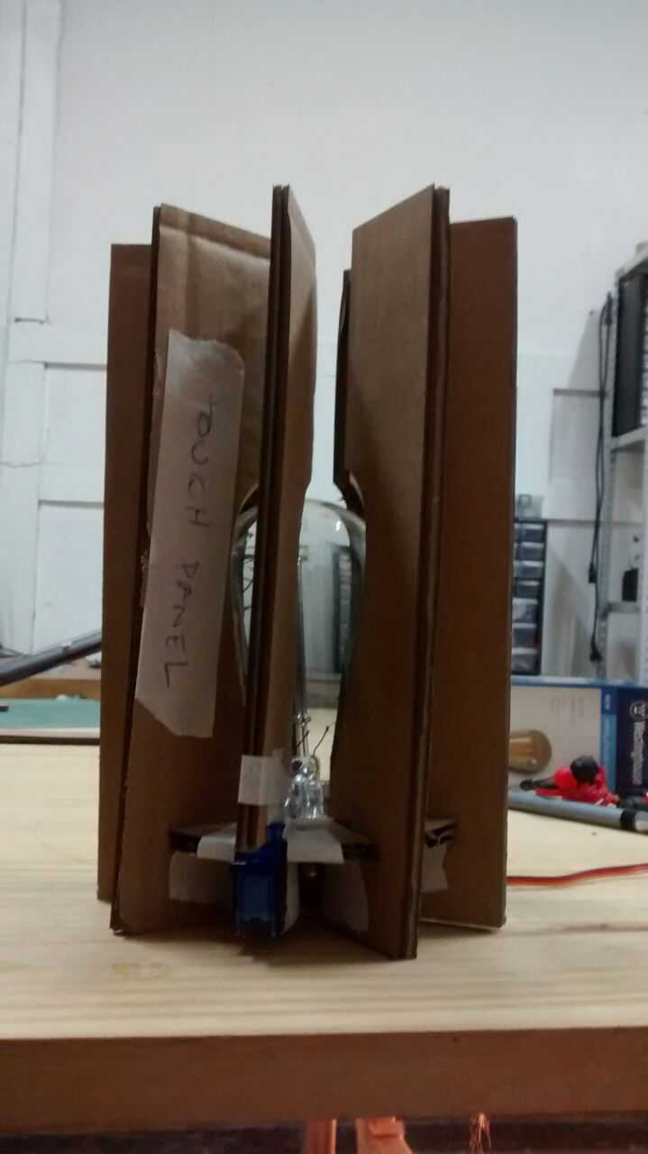
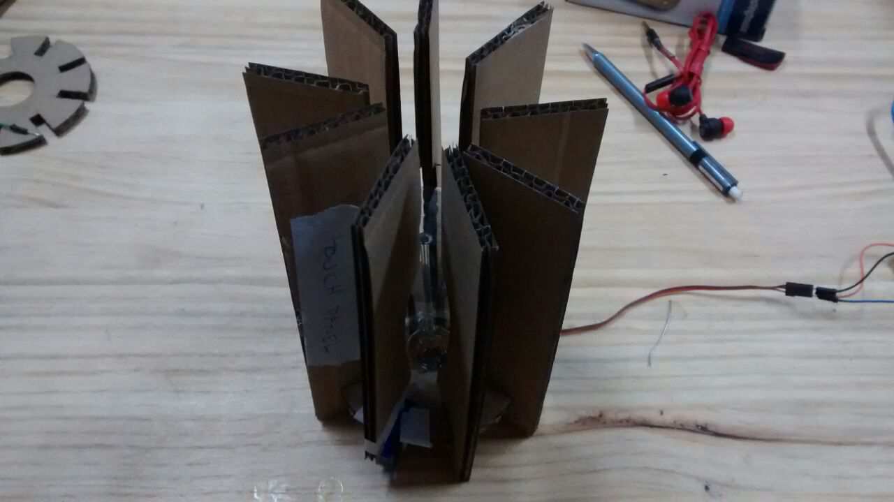
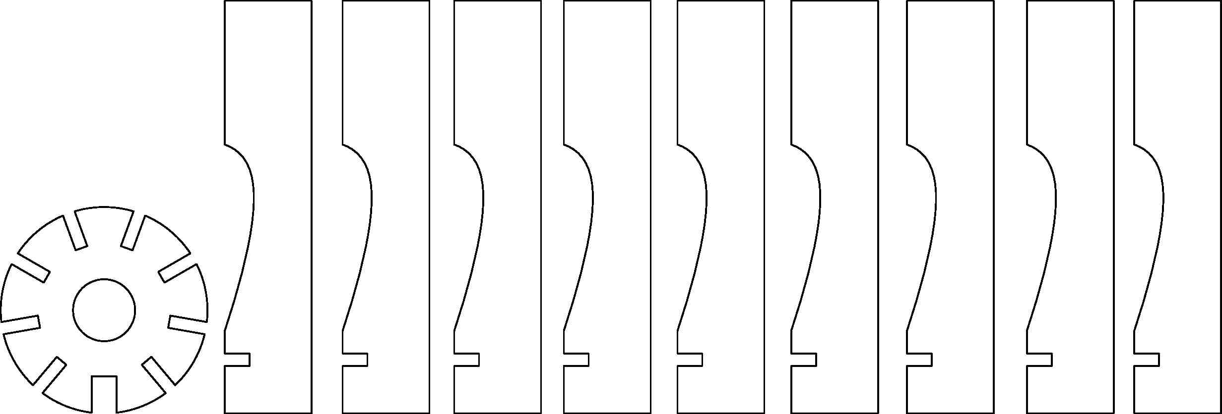
I built the final component of the lamp: the acrilic cover (here is the cutting .dxf draft)
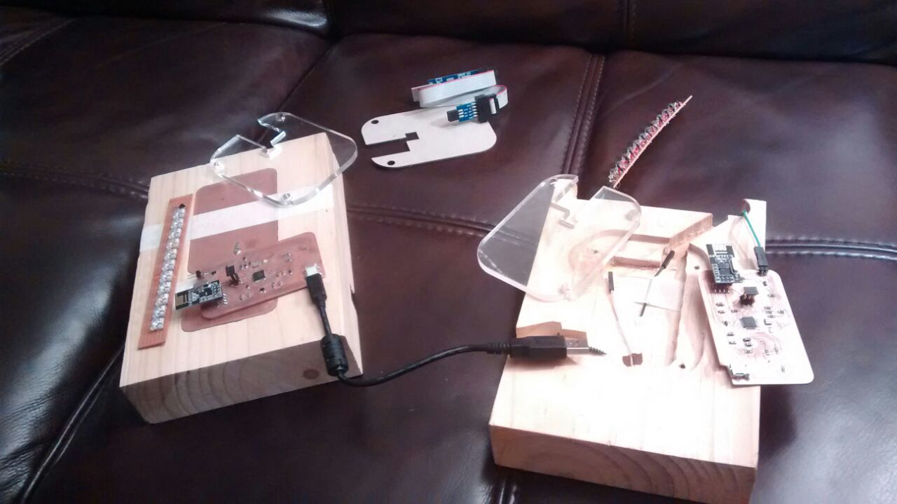
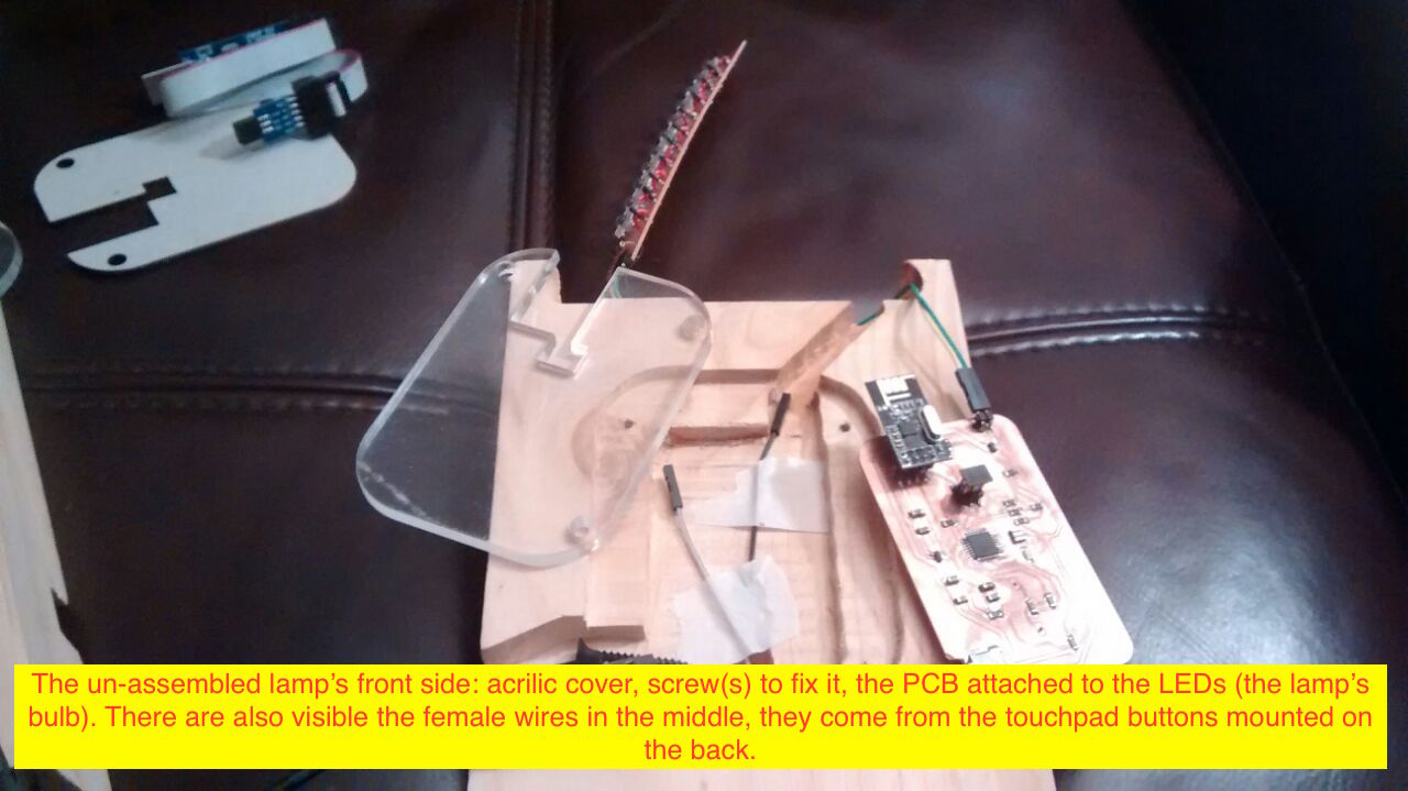
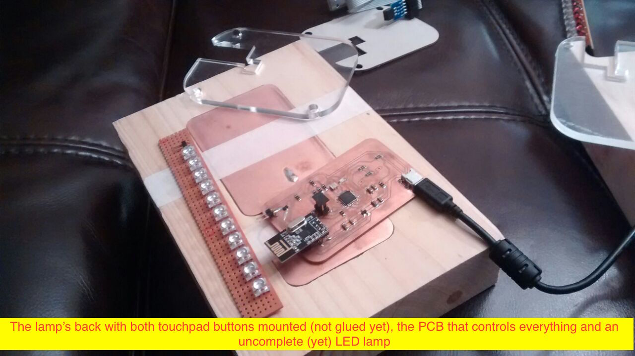
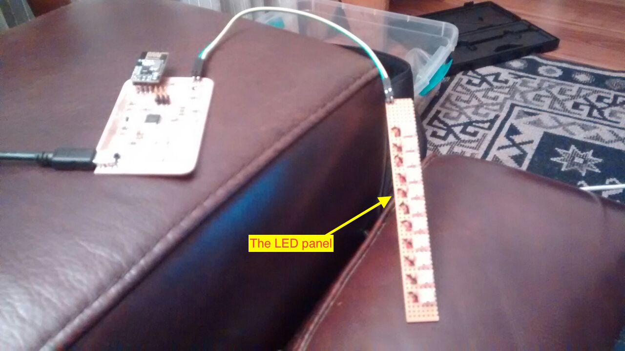
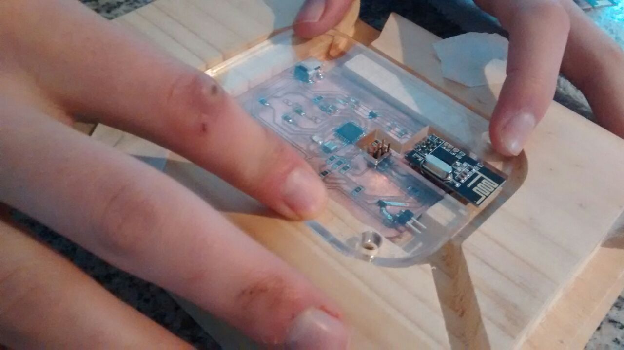
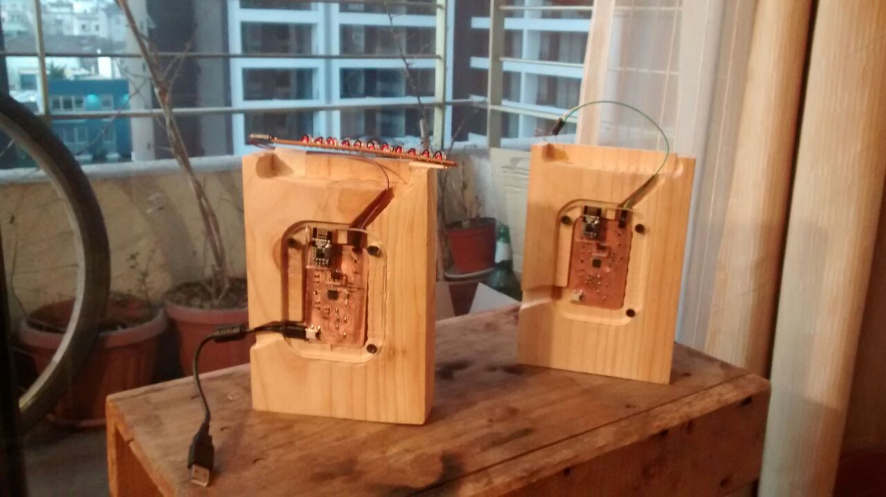
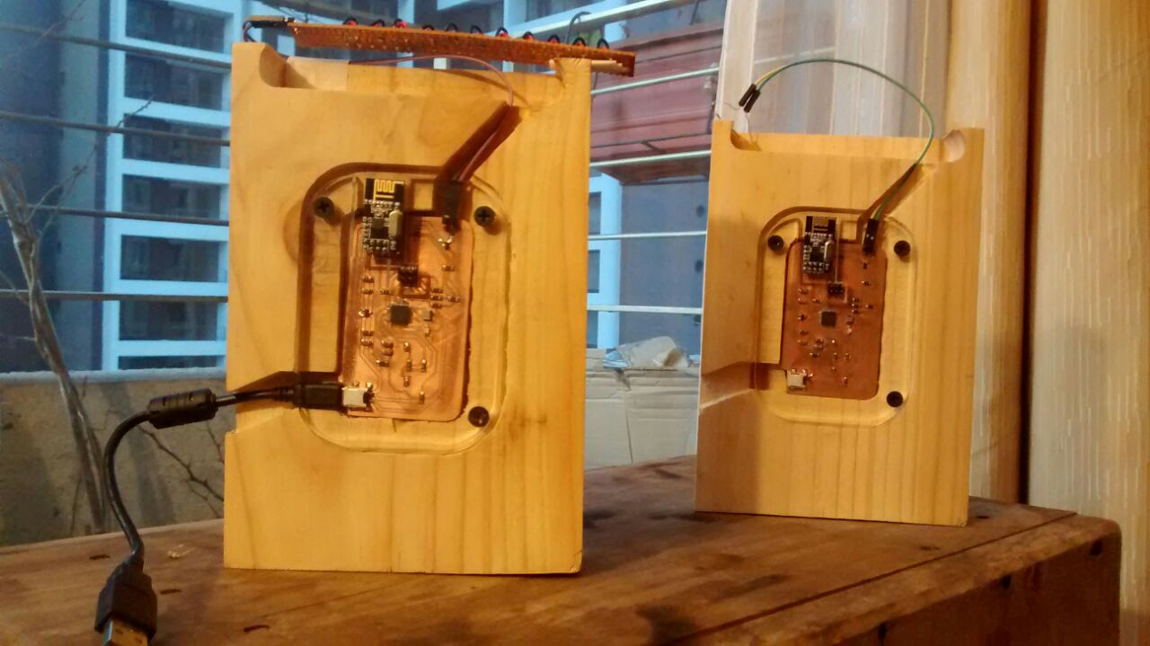
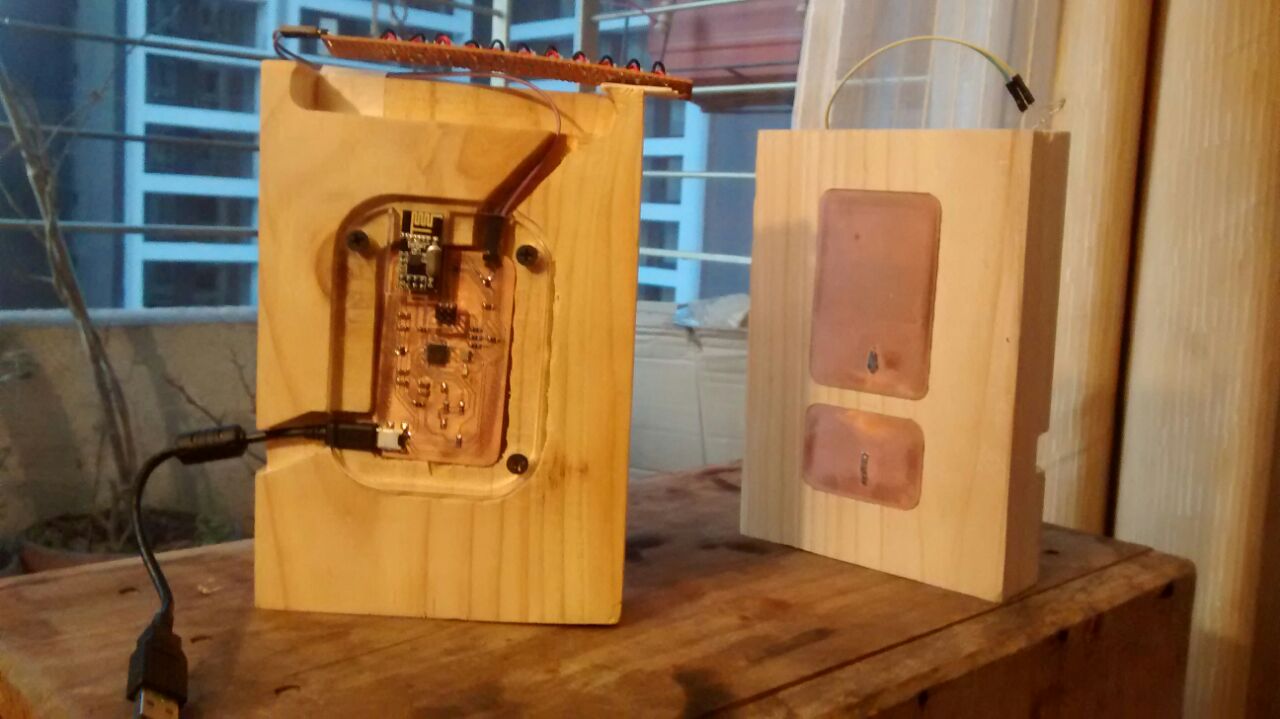
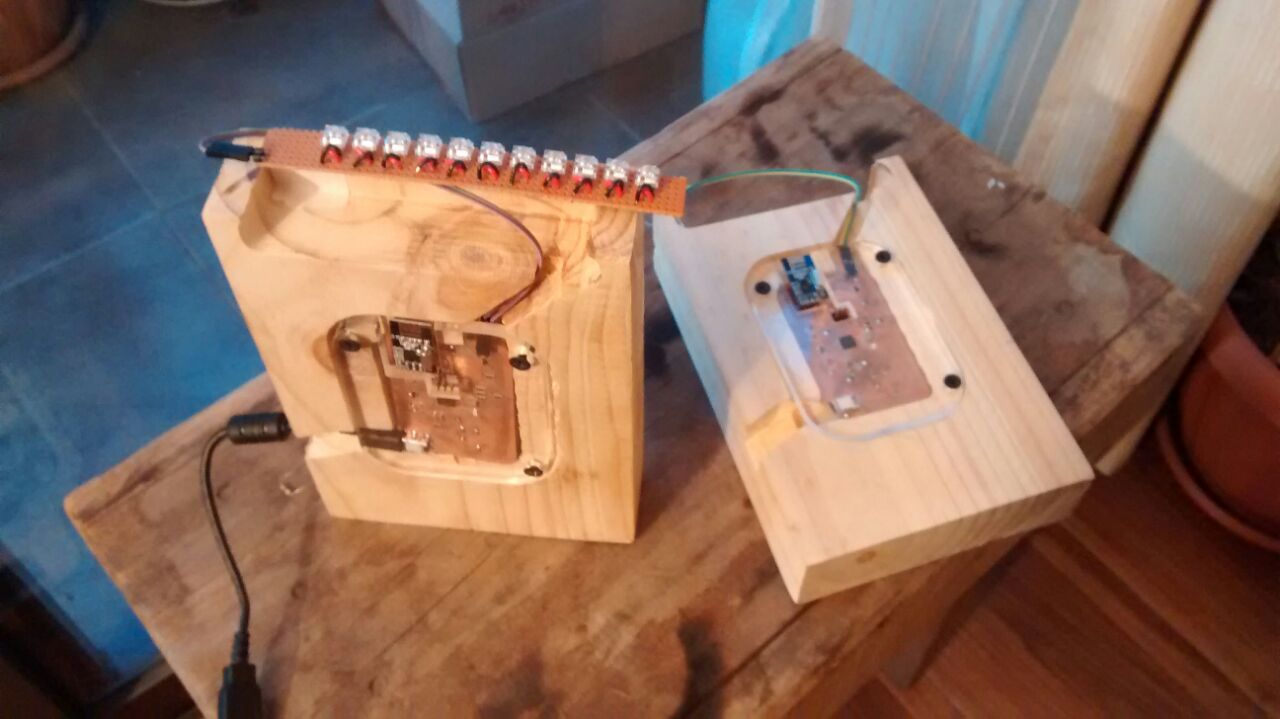
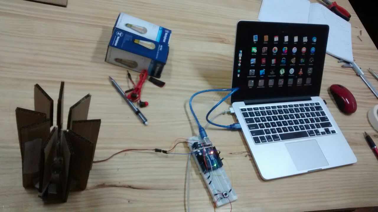
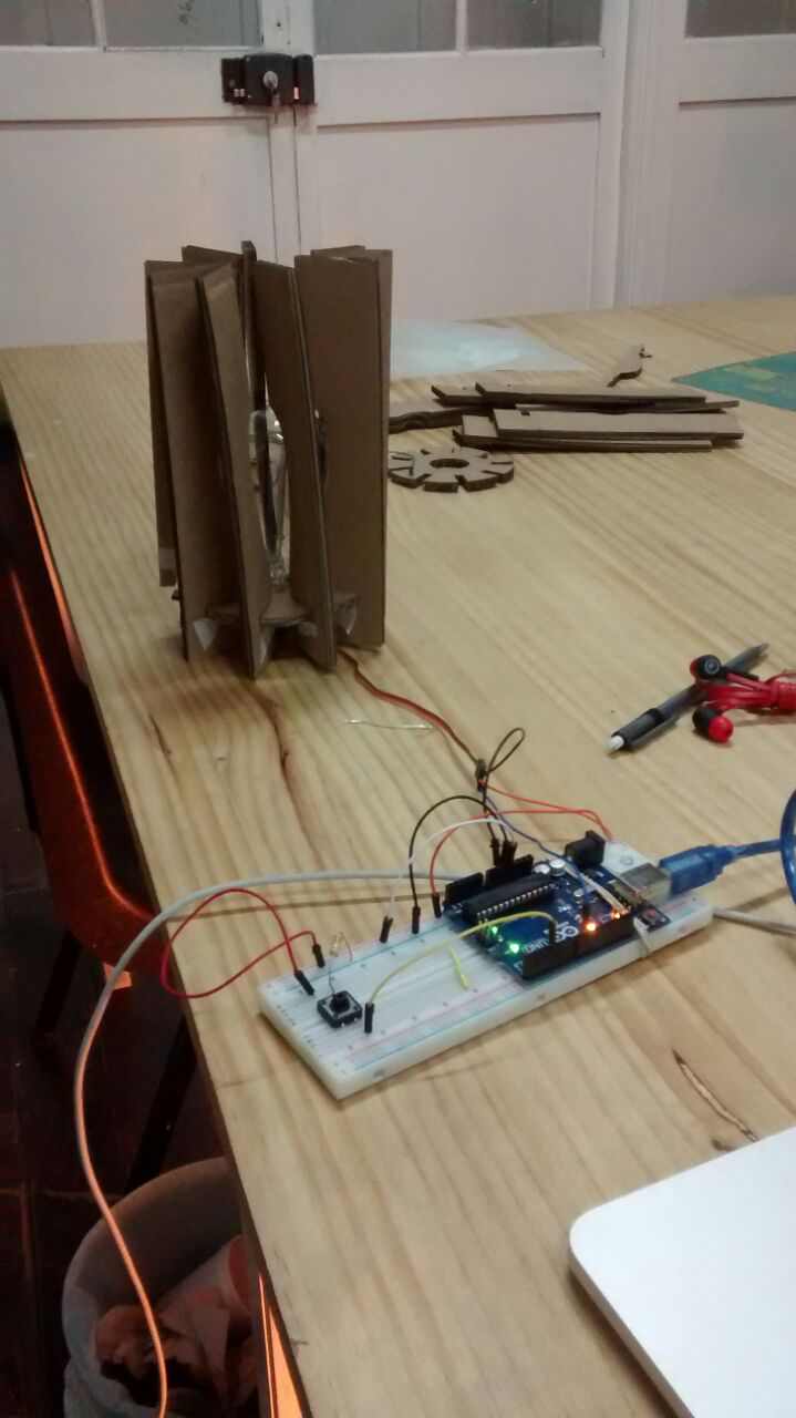
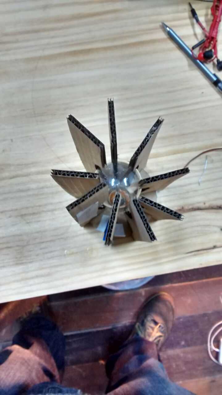
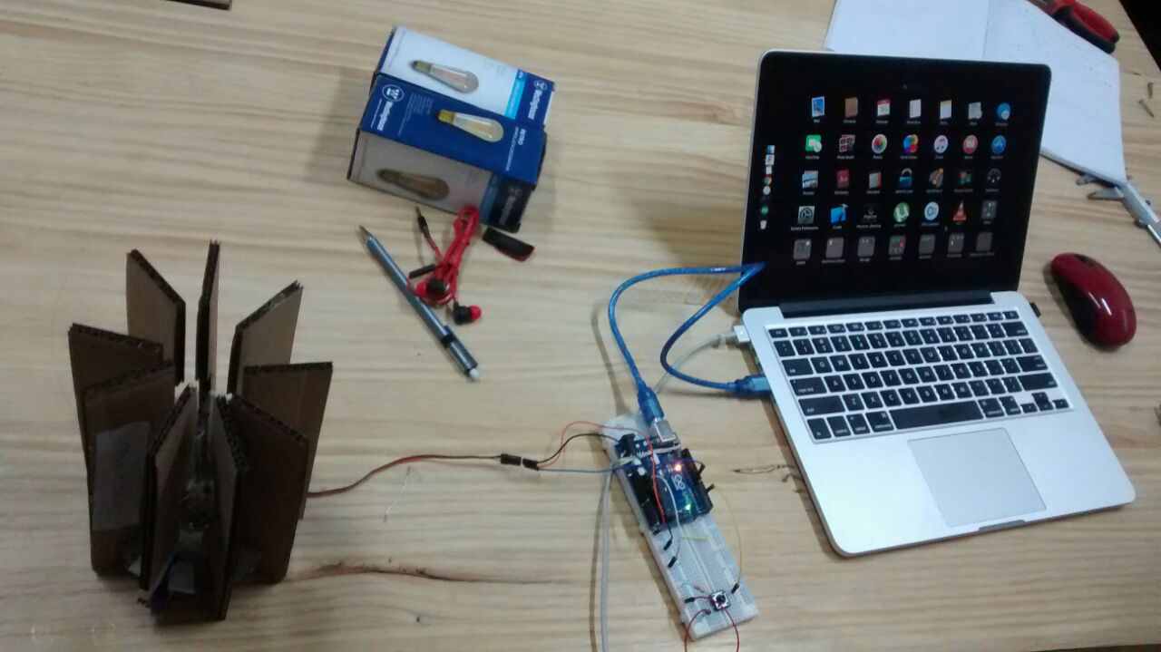
So finally I've got all the parts to assemble the lamp; a bit scattered but enough to try out all the system.
⋮
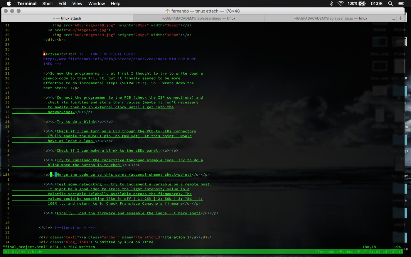
So now the programming ... at first I thought to try to write down a pseudo-code to then fill it, but it finally seemed to be more effective to do incremental steps (SPIRALLY!!). So I wrote down the next steps:
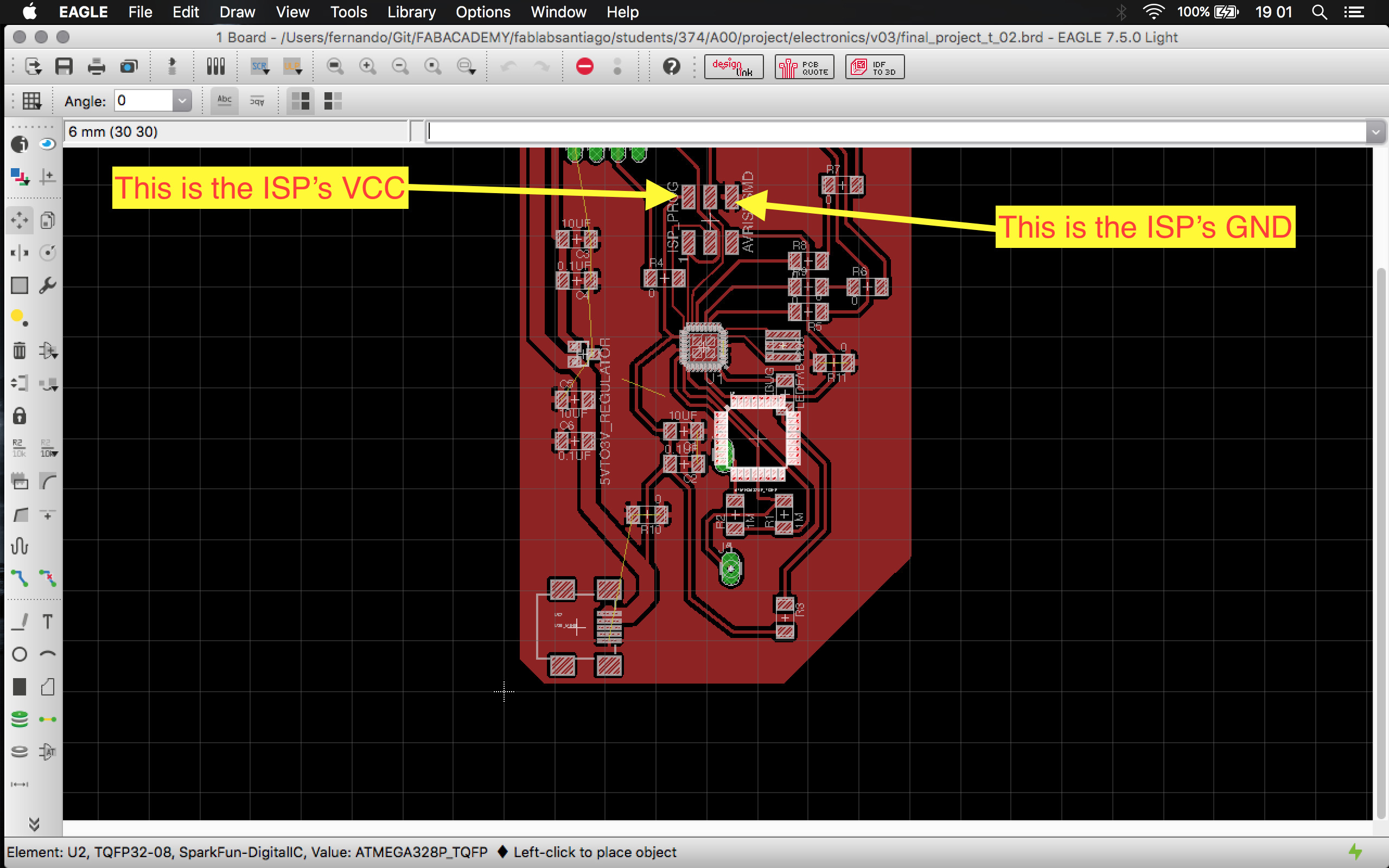
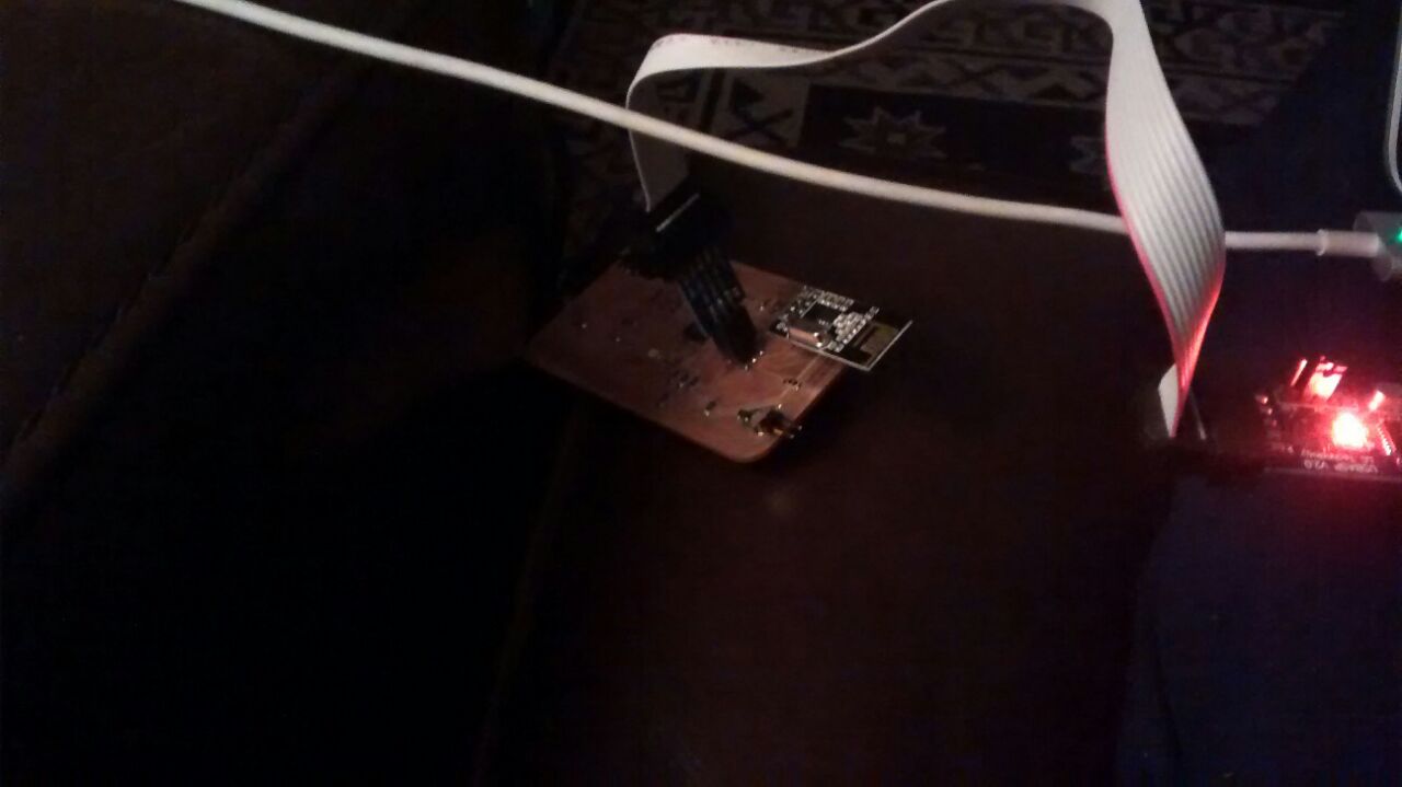
Connect the programmer to the PCB (check the ISP connections) and check its fusibles and store their values (maybe it isn't necessary to modify them to an external clock until I get into the networking).
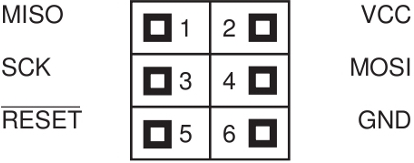
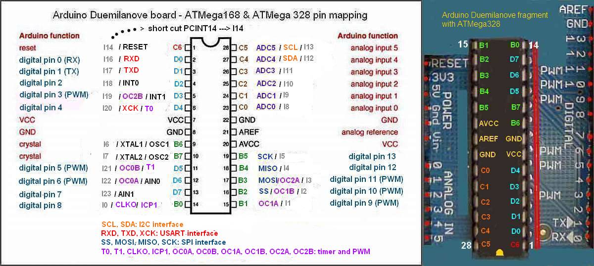
These are the ISP reference connection pins:
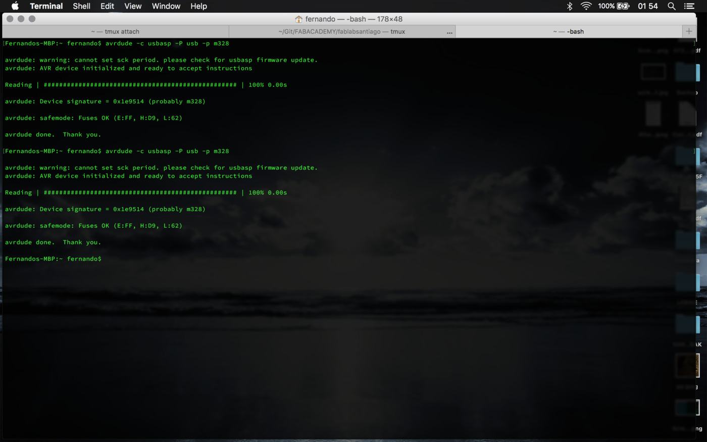
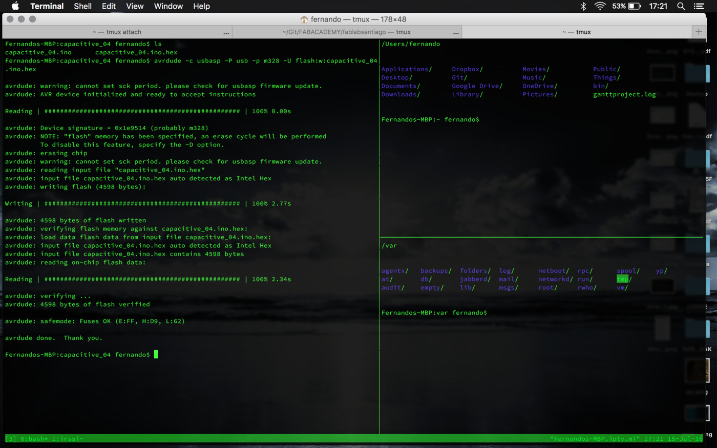
Success! by running 'avrdude -c usbasp -P usb -p m328' the programmer talked to both ICs. The fuses are E:FF, H:D9 and L:62.
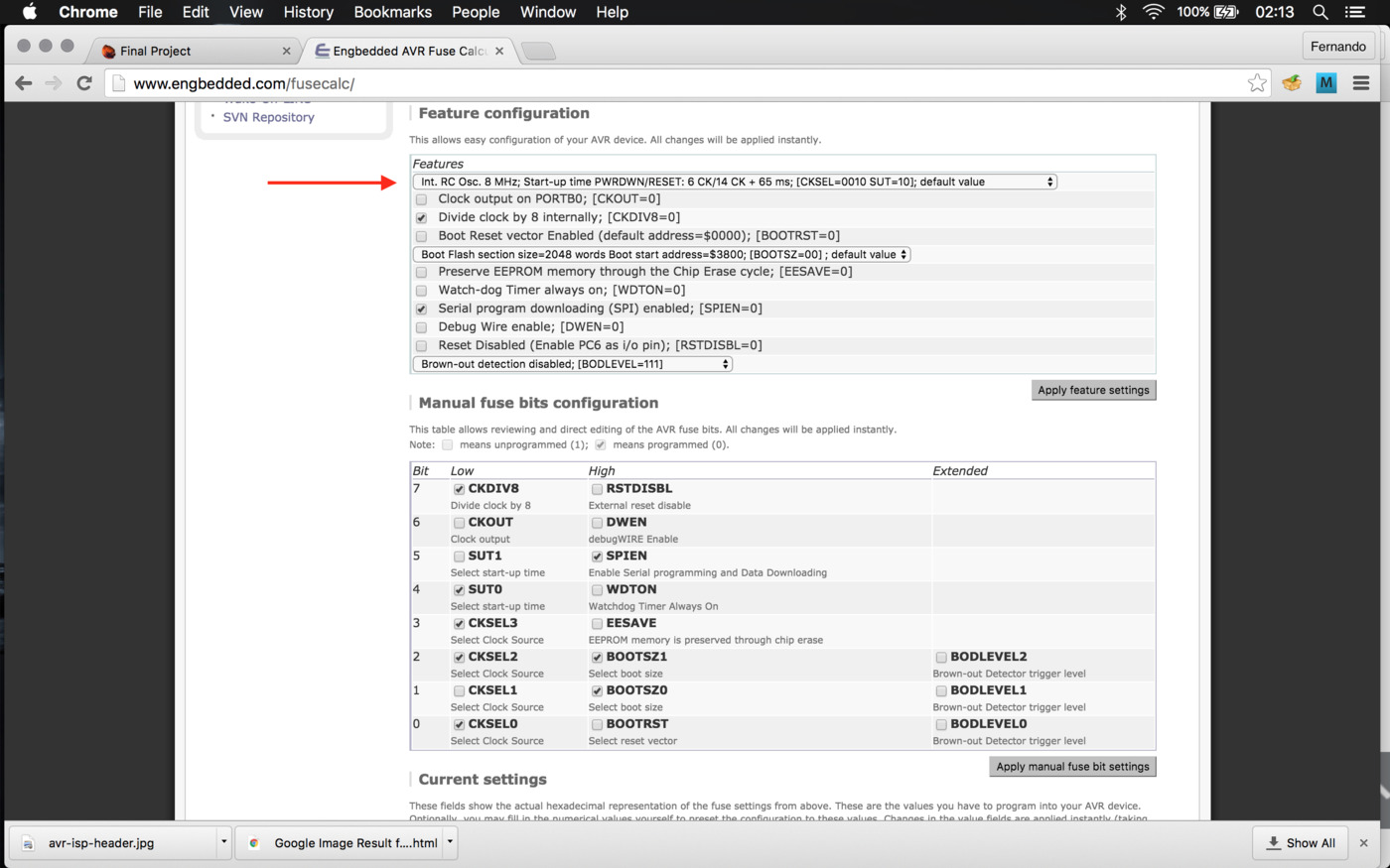
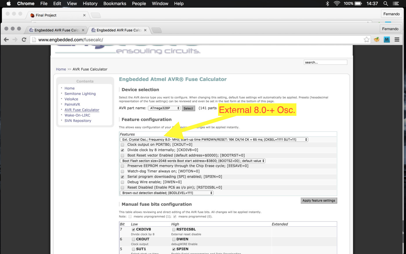
If I check the AVR Fuse calculator (note that there's only ATmega328P on the list and that avrdude distincts with the ATmega328) for this fuses they mean that the ICs are (still) configured with the internal clock (8MHz). The other parameters are no relevant this far (hope so).
Try to do a blink
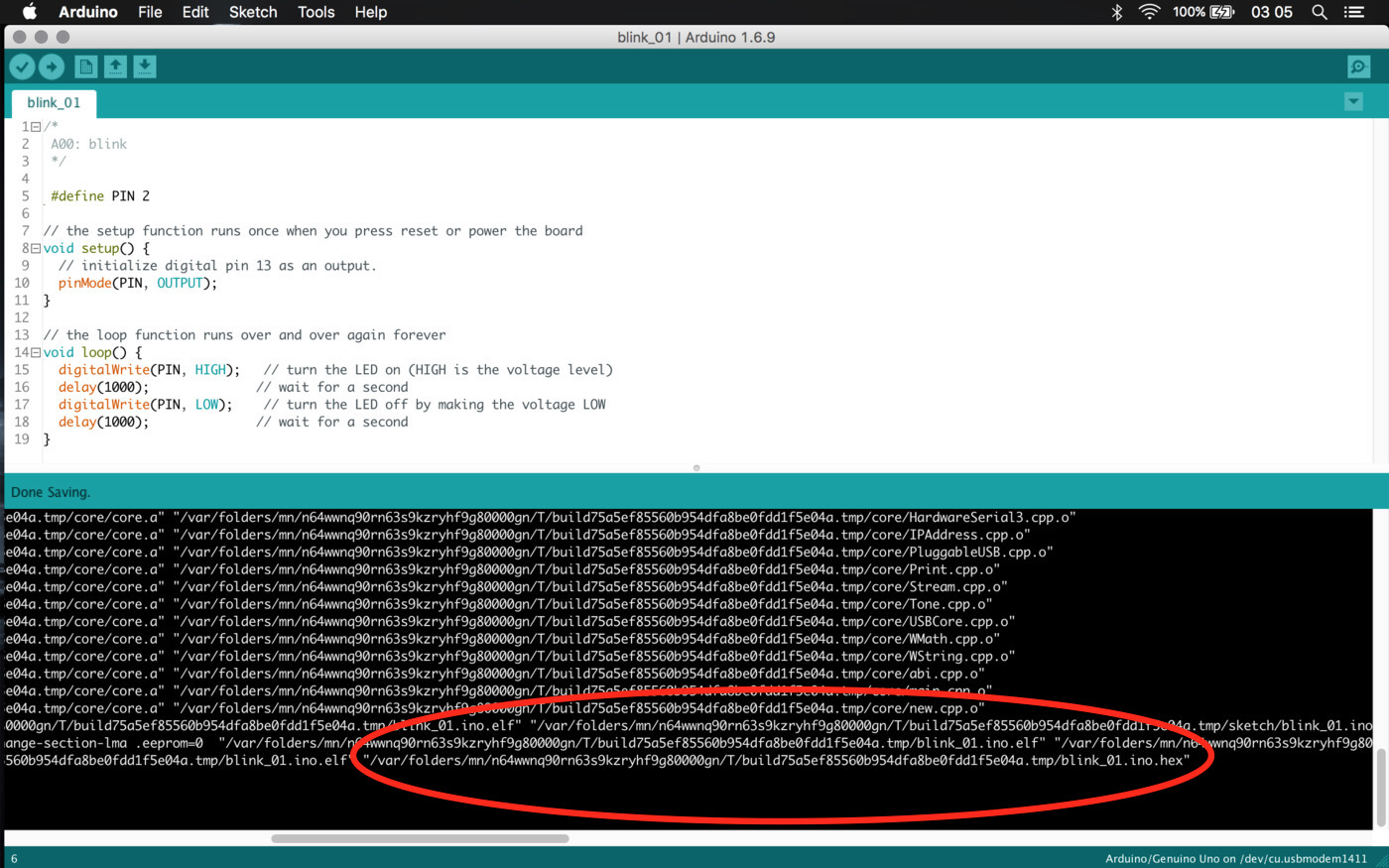
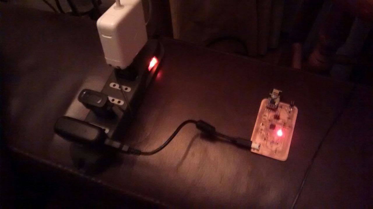
According to the schematics the onboard LED is plugged to the PD2 pin, which correspond to the "Digital Pin 2" in Arduino, so by changing the Blink.ino to that pin I should get the LED to blink. So by copying the .hex generated by Arduino (check image below) I can upload it by using 'avrdude -c usbasp -P usb -p m328 -U flash:w:blink_01.ino.hex'.
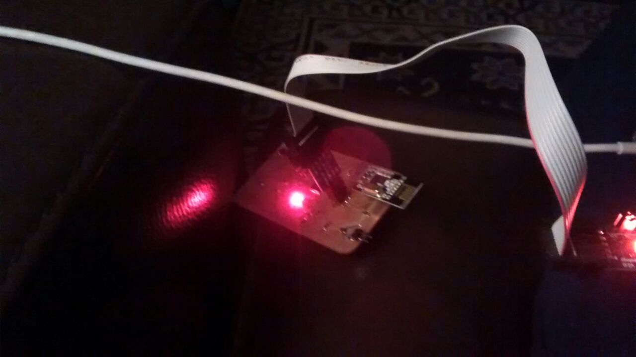
And voila! it blinks! although very slow (I'll blame the inner IC clock, since the compiled .hex must be setted up for an Arduino's 16MHhz clock). I also checked the boards powered from the USB cable, which led me to note that one of the boards blinks erratically, I checked the power and used an oscilloscope ... and re-soldered the IC's pin (the LED brightened stronger, but still weak) ... so it might be the SMD LED; I'll know on the next step when blinking with the LED panel connector.
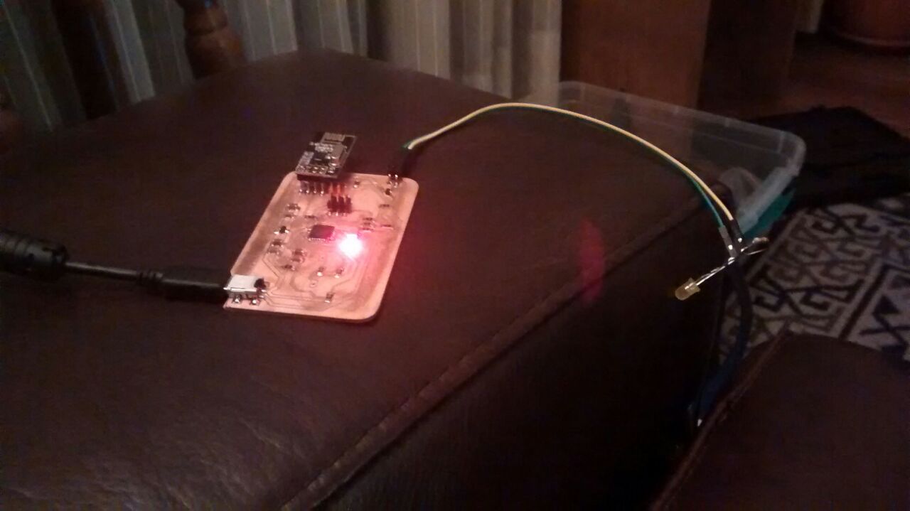
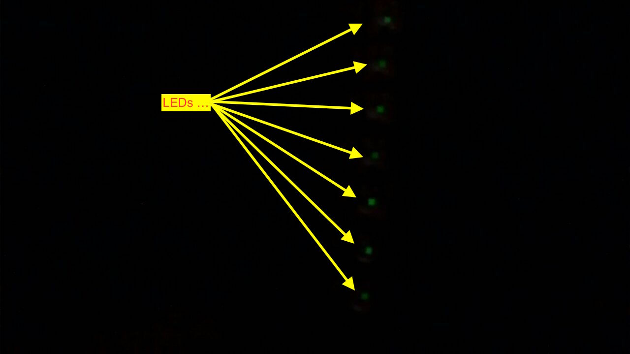
Check if I can turn on a LED trough the PCB-to-LEDs connectors (fully enable the MOSFET pin, no PWM yet).Check if I can make a blink to the LEDs panel ... at this point I would have at least a lamp!
Again, accoding to the schematics the MOSFET/PWM pin is the PB2 pin, which correspond to the "Digital Pin 10 (PWM)" in Arduino. Following the steps done before (above) I have these sketch and .hex
⋮And it worked! Although with the LED panel it barely illuminated (I verified the power source and it provides only 400mA, much less than the 2A power adapter I intend to use, so there's still hope).
EXTRA_01: When testing this code on the erratic board plugged to the USB cord I found that there was no voltage between the USB's VCC and GND, so by inspecting the plug closely I noted the first pin (VCC) and the second are soldered that might be causing a short circuit when plugged; the same happens with the 5th (GND) and the 4th, but I discard this because the board that works well also have this pins soldered.
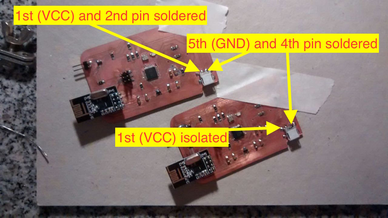
EXTRA_02: It resulted that although that 1st and 2nd pins won't connect to GND, when I plug the USB cord with the transformer (no power feeded yet) they DO connect VCC and GND, so that would explain the malfunction. Solution, to unsolder the 2nd pin somehow (is to tiny!).
EXTRA_03: We got to desolder the conflictive pins and this corrected the USB powering issue of connecting VCC and GND, but the malfunction persisted (curiously only with the USB cord, with the ISP it works well) ...
EXTRA_04: After a while and with no further intervention (we only connected the oscilloscope's GND) the 'malfunctioning' PCB started to work (a bit erratically)... I'm starting to blame the solar storms and Murphy's Lawright now.
Try to run/load the capacitive touchpad example code. Do a blink when the button is touched.
As I'm kind of in a hurry I went to the sure thing, the Arduino Capacitive Sensing Library with a very good explanation of how it workѕ (I want to re-code everything after on C!). NOTE that getting this examples to work might need to change the IC's fuses to work with the external 20Mhz clock (so far I'm still working with the internal 8Mhz clock); it might be wise to do this first on the erratic IC to verify communication afterwards with the programmer.
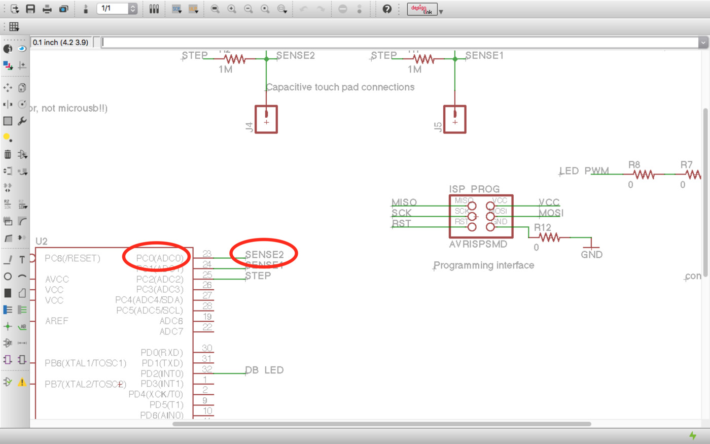
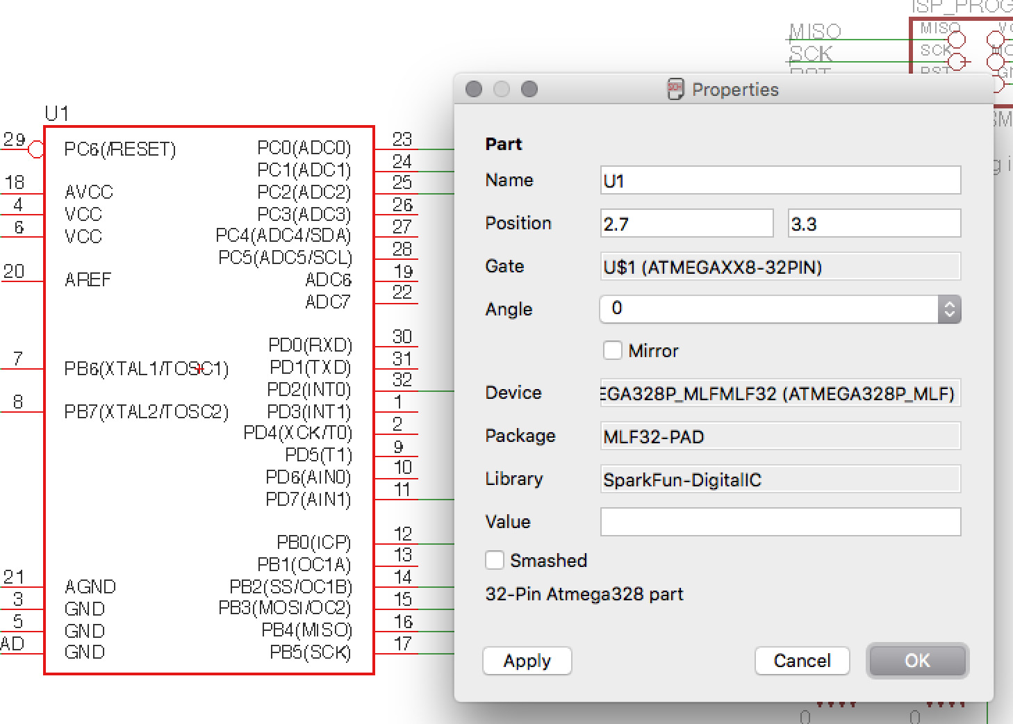
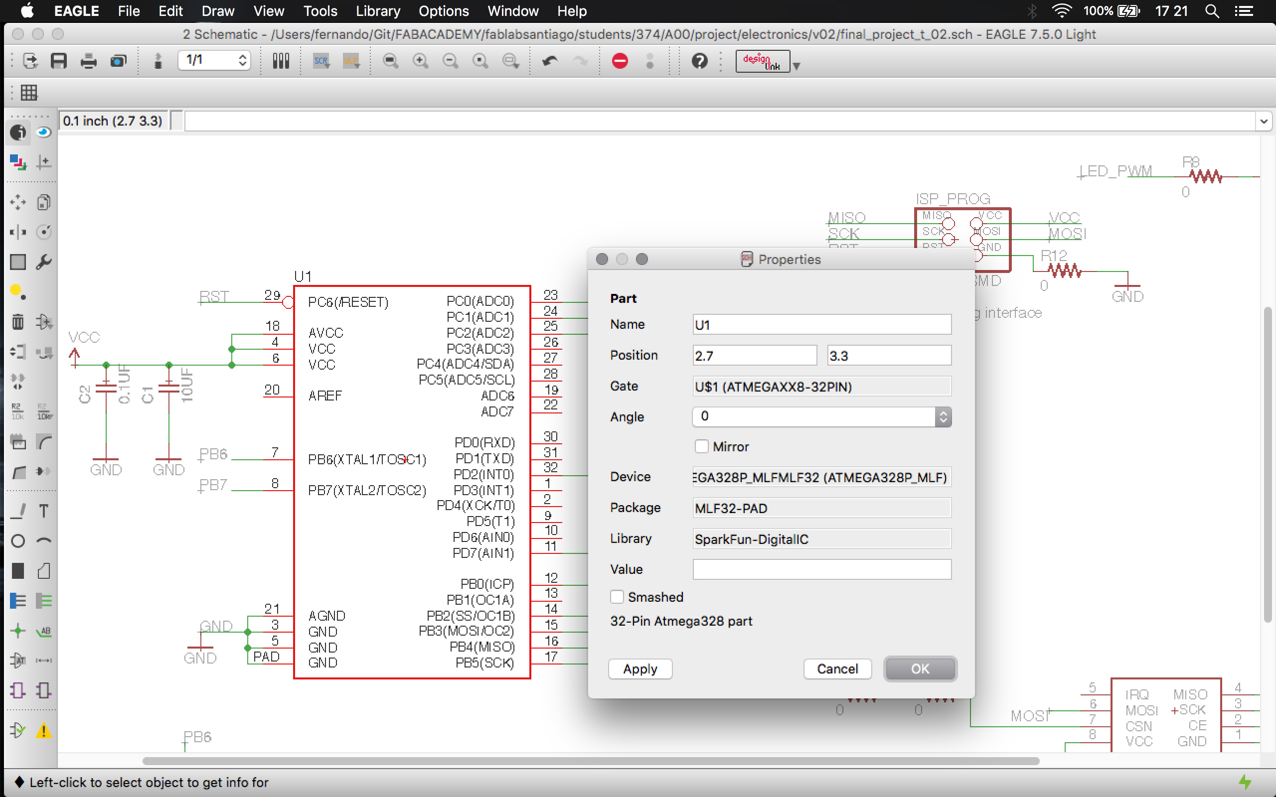
Here is the CapacitiveSensor.ino original example. And, as in the previous steps, the Pulse Pin is the PC2 (Analog 2 == Digital Pin 16) pin and the sensing pins are the PC1 (Analog 1 == Digital Pin 15, small button) and PC0 (Analog 0 == Digital Pin 14, large button). Here are the schematic , pin equivalence and the pin reference.
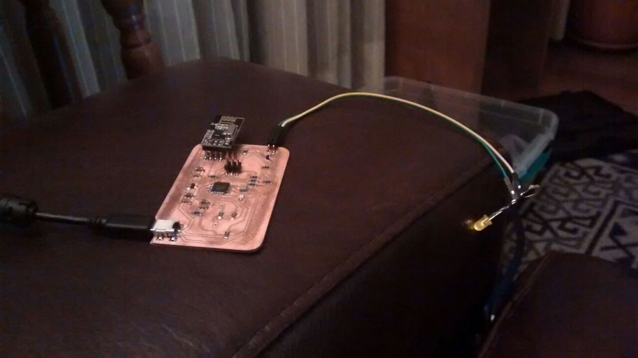
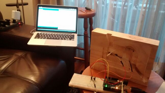
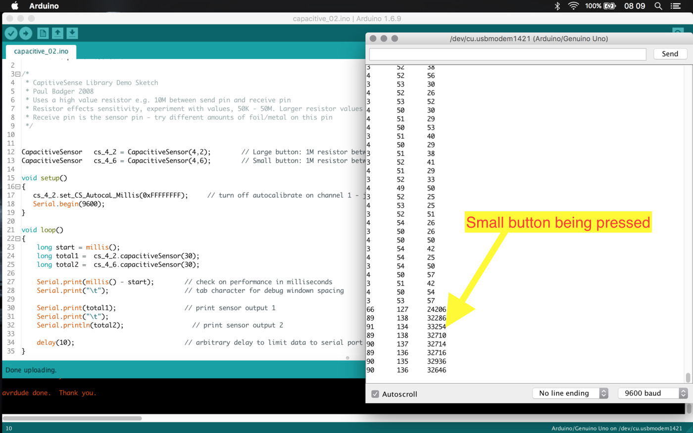
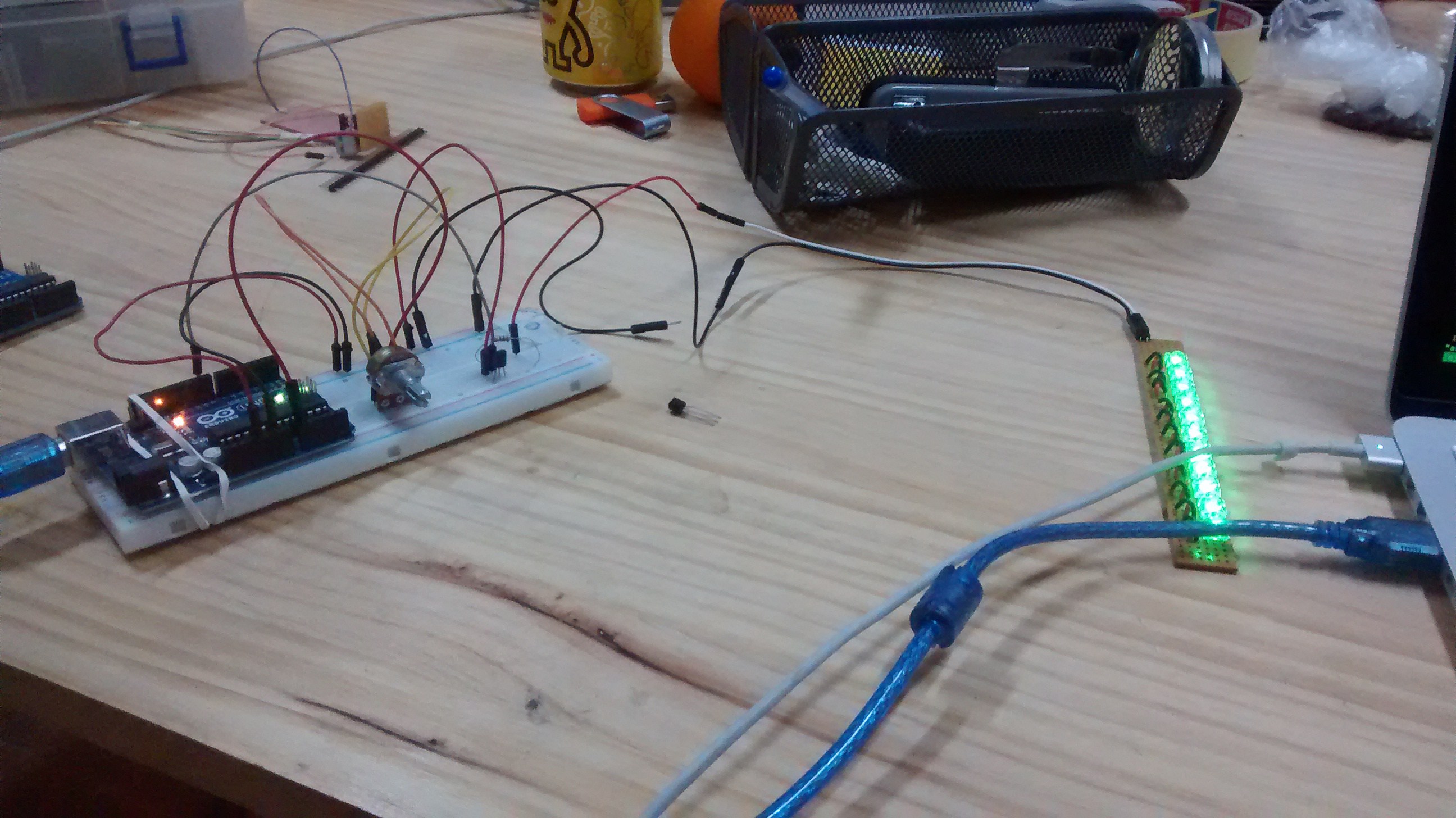
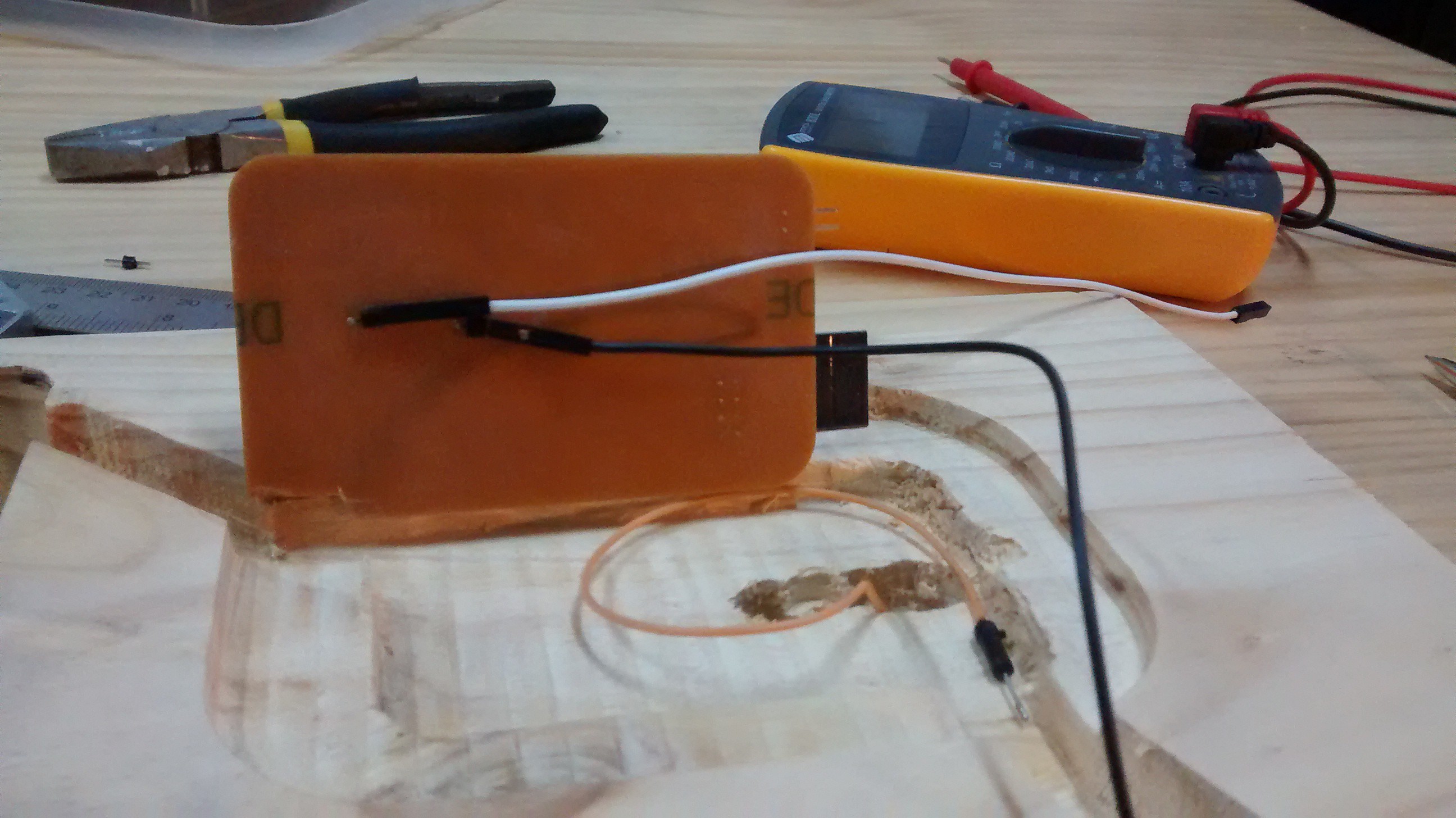
By studying the library's example and this Instructable I checked that I need to determine some response time values, so I'll execute the first example on an Arduino attaching my lamps touchpads and 1M resistors, as it is built in my PCB.
And I got a little victory ... the code works and I was able to measure the buttons with the same connections I have in my PCB
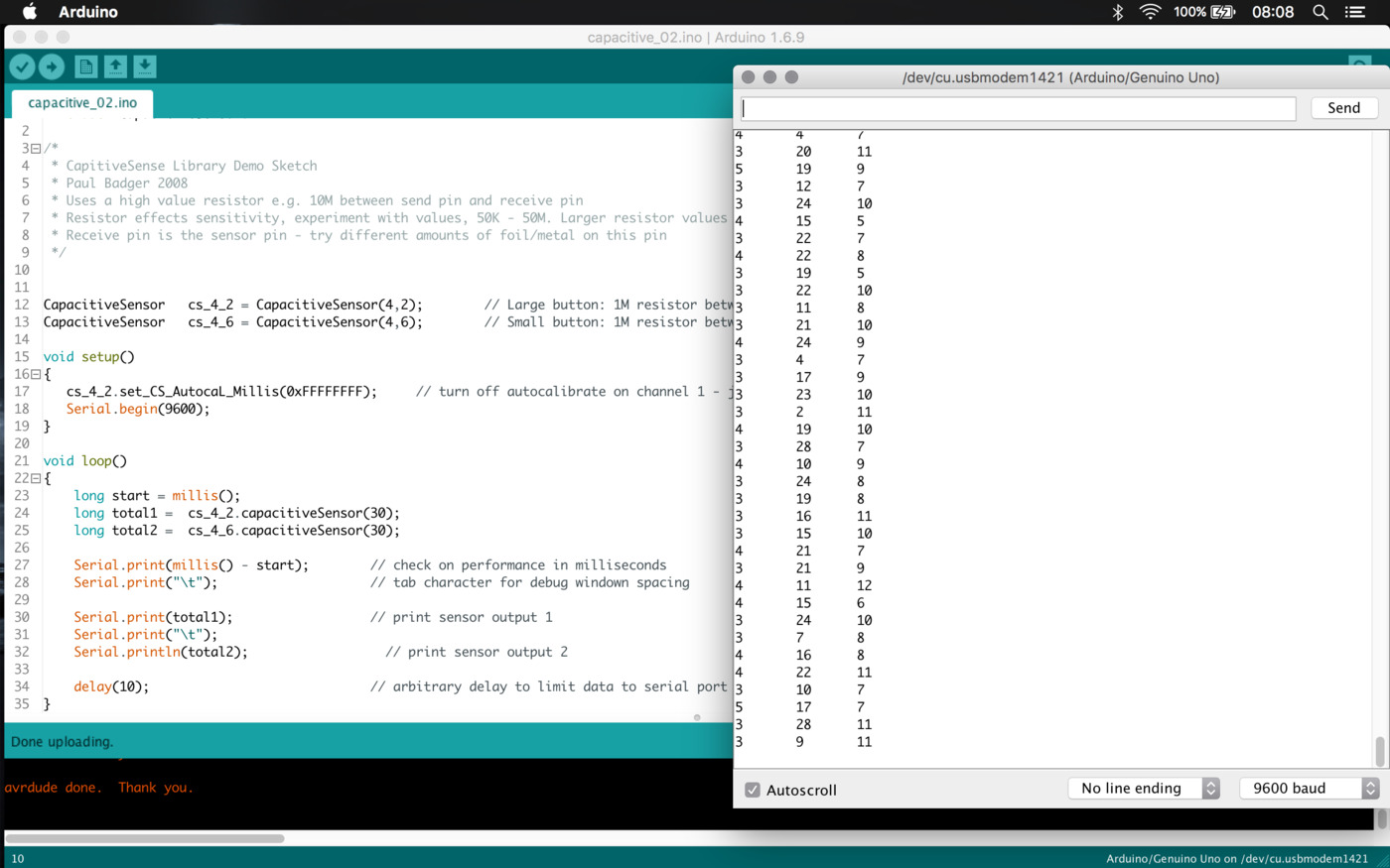
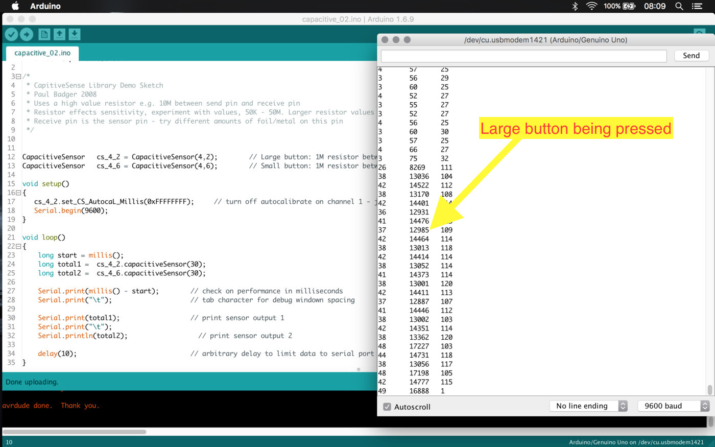
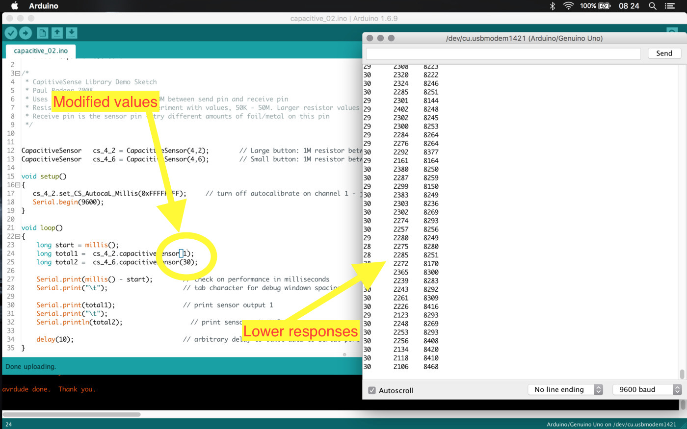
By changing a little bit values around I found that if I decrease the step pulse time I get a more responsive feedback (not sure), so I'll leave those values low. Here is the sketch.
So I made a simple blink using the touchpads and the LED on the pin 13 of the Arduino Uno using this sketch
Merge the code up to this point (accomplishment check-point)
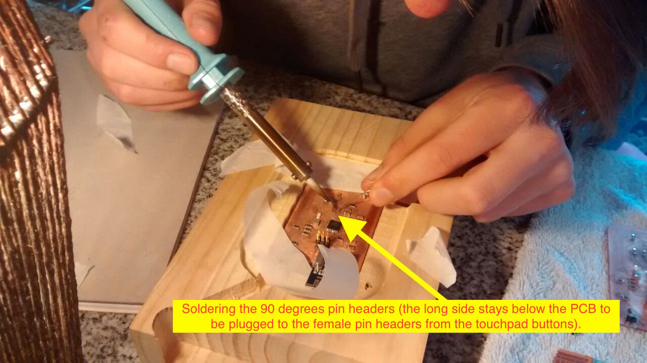
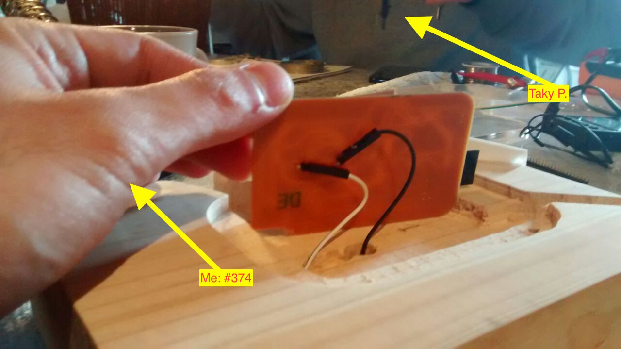
At this point I need the PCB connected to the touchpad buttons, luckily I got help to solder from my friend Taky Parvex ...
I'm also switching the fuses to use the external 20MHz resonator
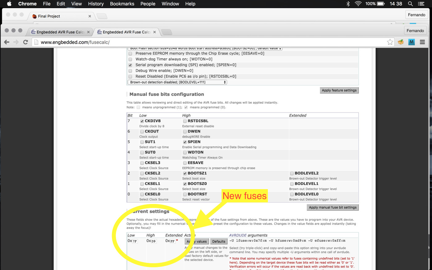
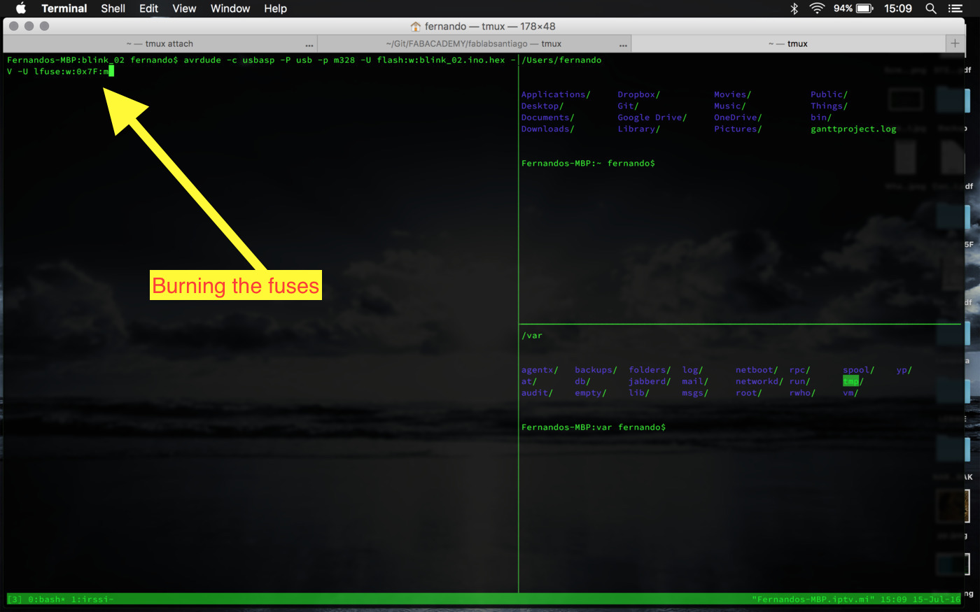
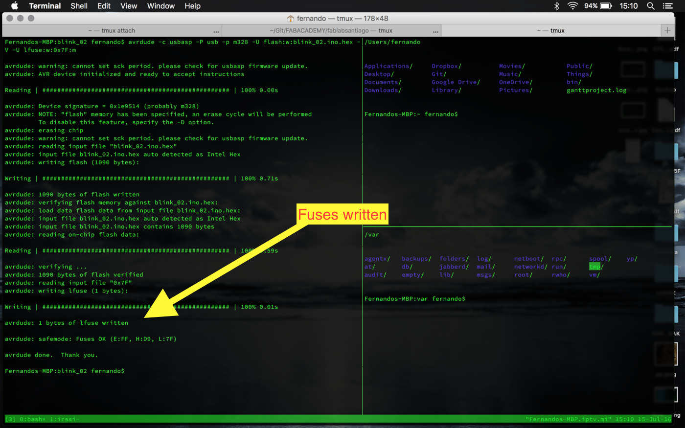
So the only fuse needed to be changed is the Lower Fuse, from 62 to 7F, which is done by running 'avrdude -c usbasp -P usb -p m328 -V -U lfuse:w:0x7F:m'
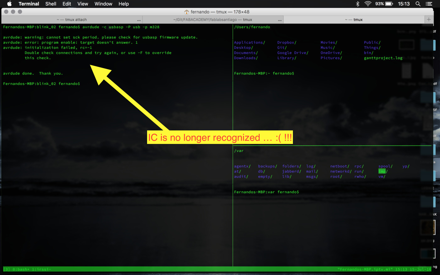
Catastrophe!!! One of the PCB is dead now and the other only works
when plugged to the ISP connector, although we were able to
un-solder the 1st and 2nd pin of the USB connector, the
malfunction persists when powering from USB (see
EXTRA_03 EXTRA_04 above).
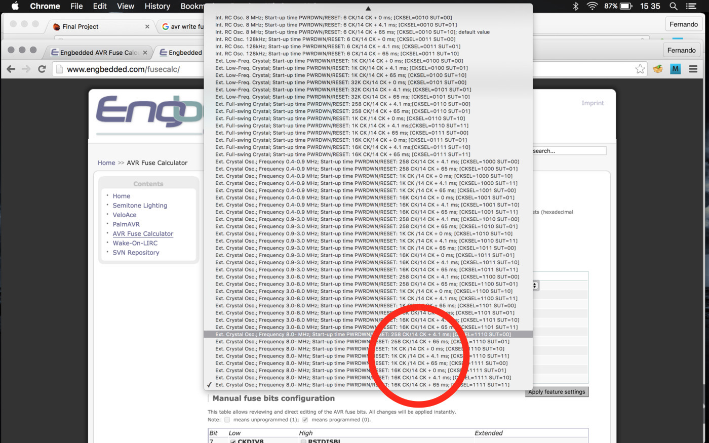
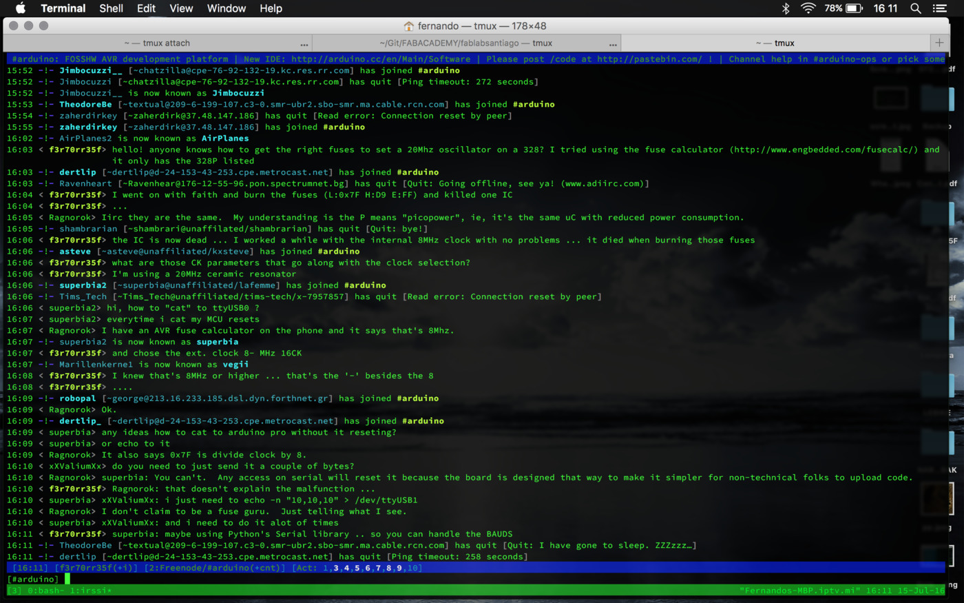
One of the possible issues when burning the fuses are those CK options on the Fuse Calculator. I might have mistaken there or maybe was the fact that there was no ATmega328 (not the 328P) on the list ... and according to the IRC dudes (#arduino on Freenode) the notation shouldn't be the problem ...
Taking in account all the (not so pleasant) events, it seems that
the only things left to do are 1. to make one lamp to light the bulb
with іts touchpad and ⒉. to take the hero shot.
1. So here is the sketch and .hex files used. The result was that the LED got to blink during short time intervals according to the touchpad's actuation, but most of the time erratically ... and since I'm carrying both the powering and the clock issues from before ... I can't really explain now what's the problem ... at least it worked a while :)!!!
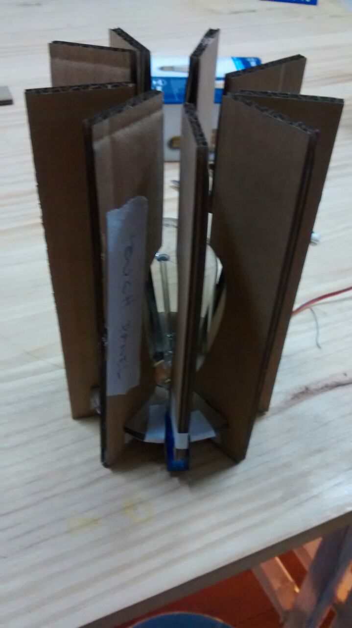
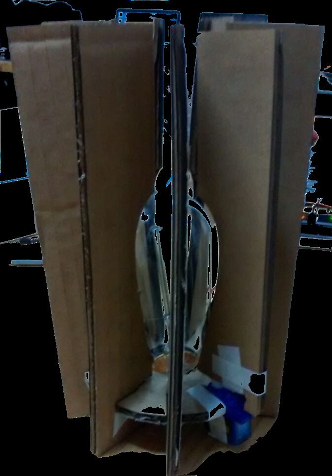
2. And finally the hero shot
Test some networking -- try to increment a variable on a remote host. It might be a good idea to store the light intensity value in a Volatile variable (globally available across the firmaware). The values could be something like 0: off | 1: 25% | 2: 50% | 3: 75% | 4: 100% ... and return to 0. Check Francisco Camacho's firmware
Finally, load the firmware and assemble the lamps --> hero shot!
There's been a lot of work in this iteration:
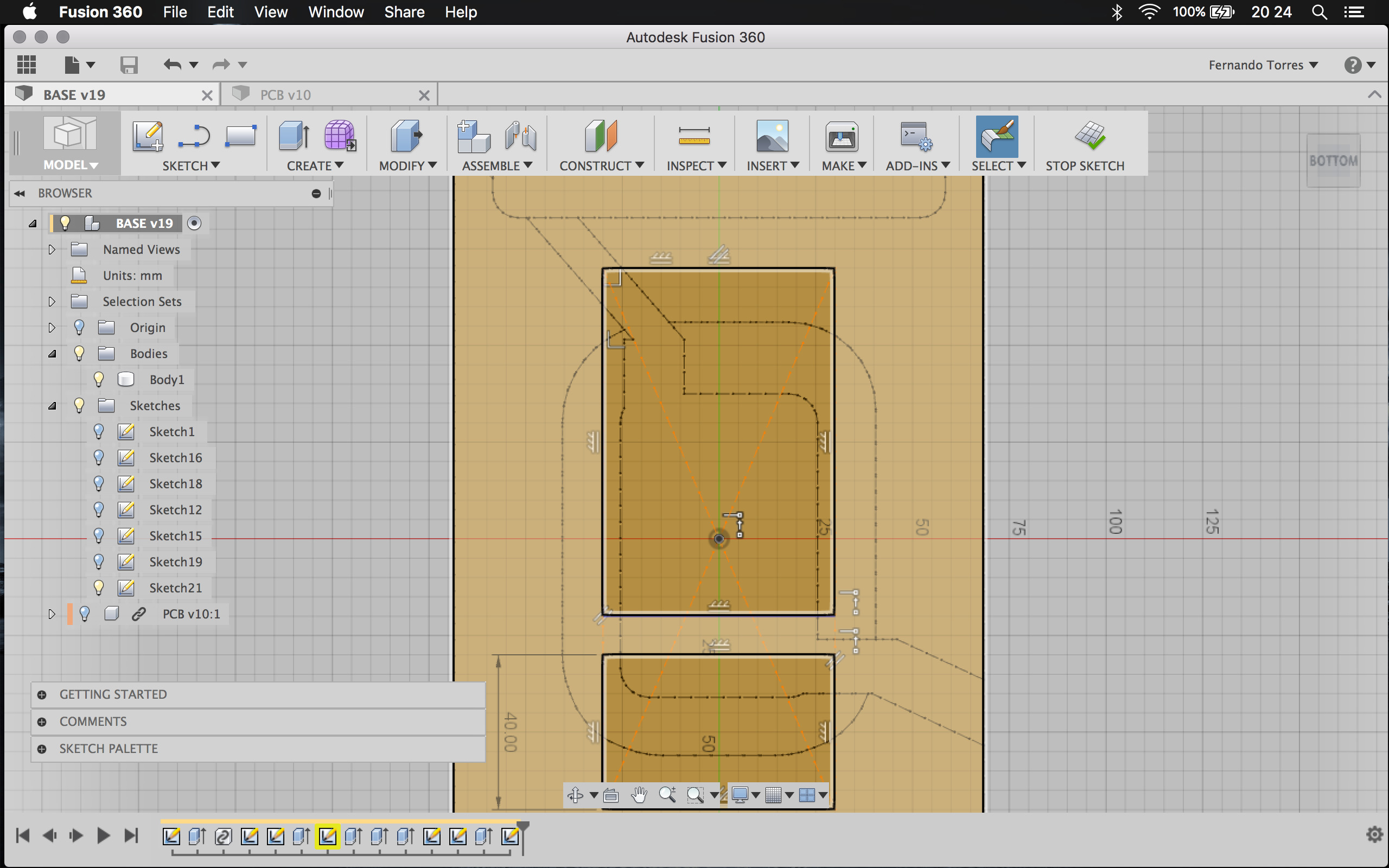
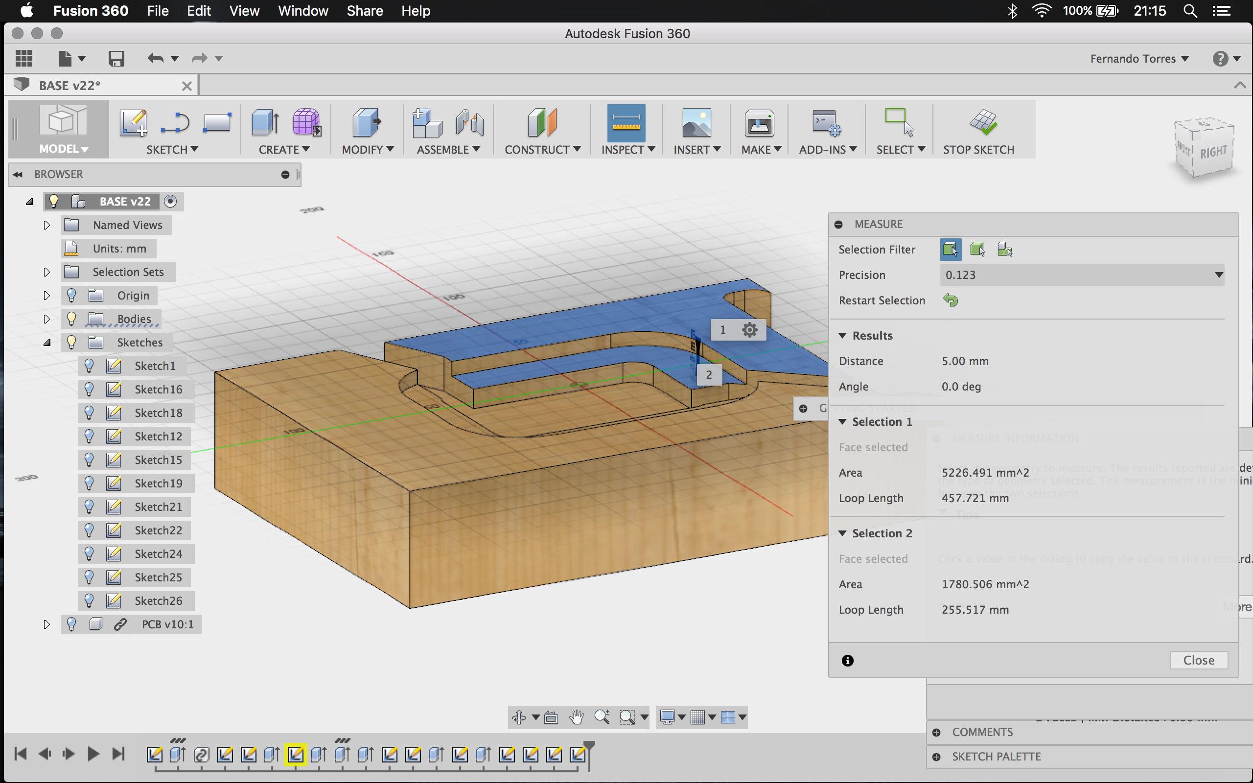
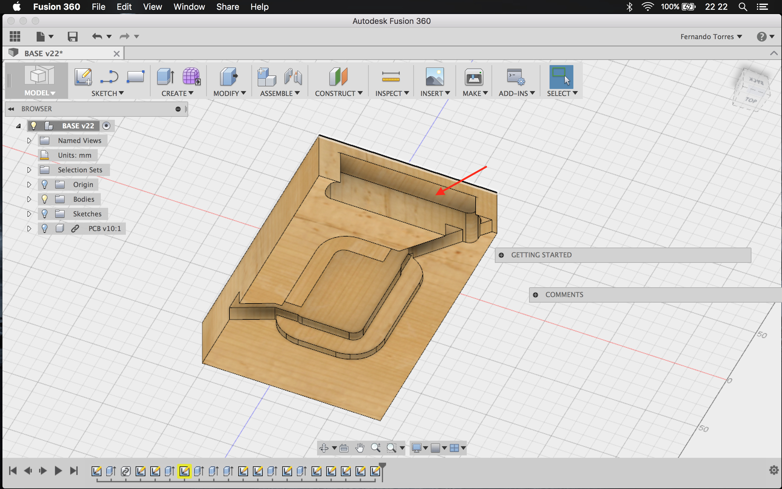
I had to redesign the lamp due to some fitting issueѕ I found on the previos model (e.g. the USB cable didn't fit inside the electronic's space. I redraw the lamp on Fusion360 to have more control on the modifications. Here are the lamp's cutting drafts (top 01, top 02 and bottom).
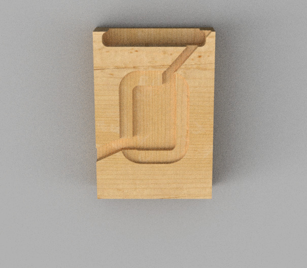
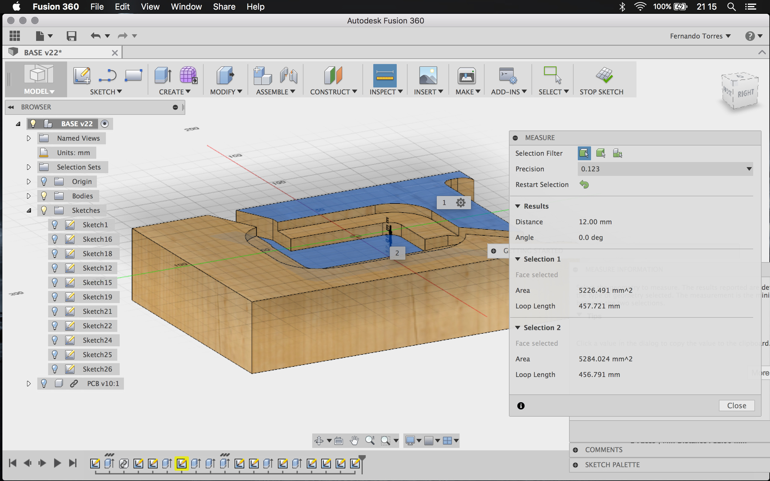
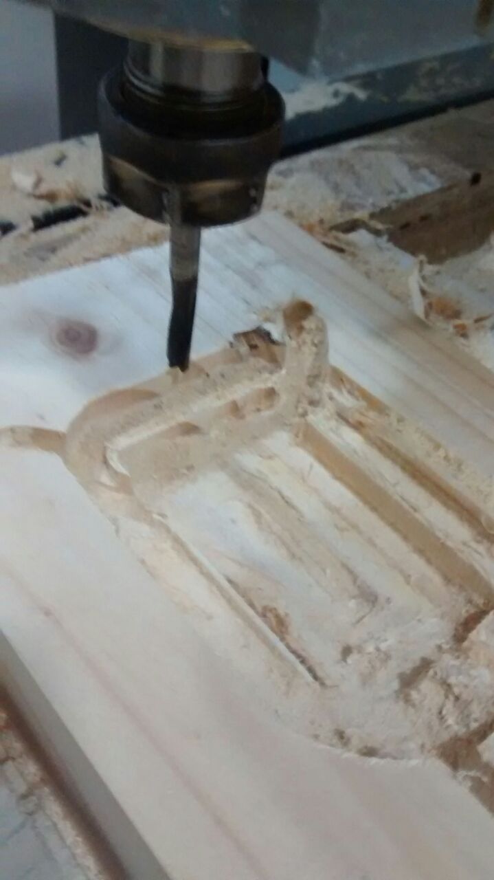
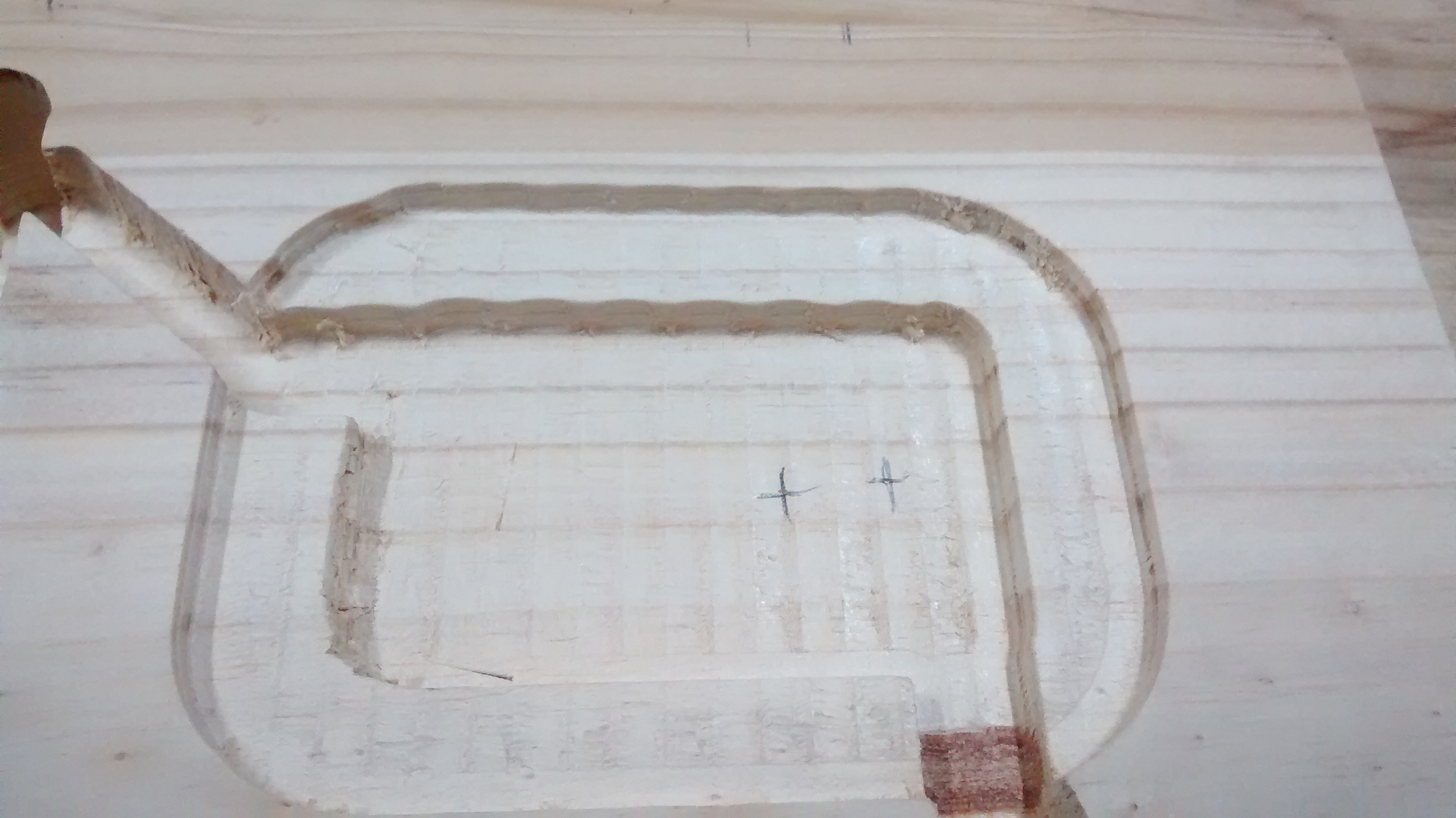
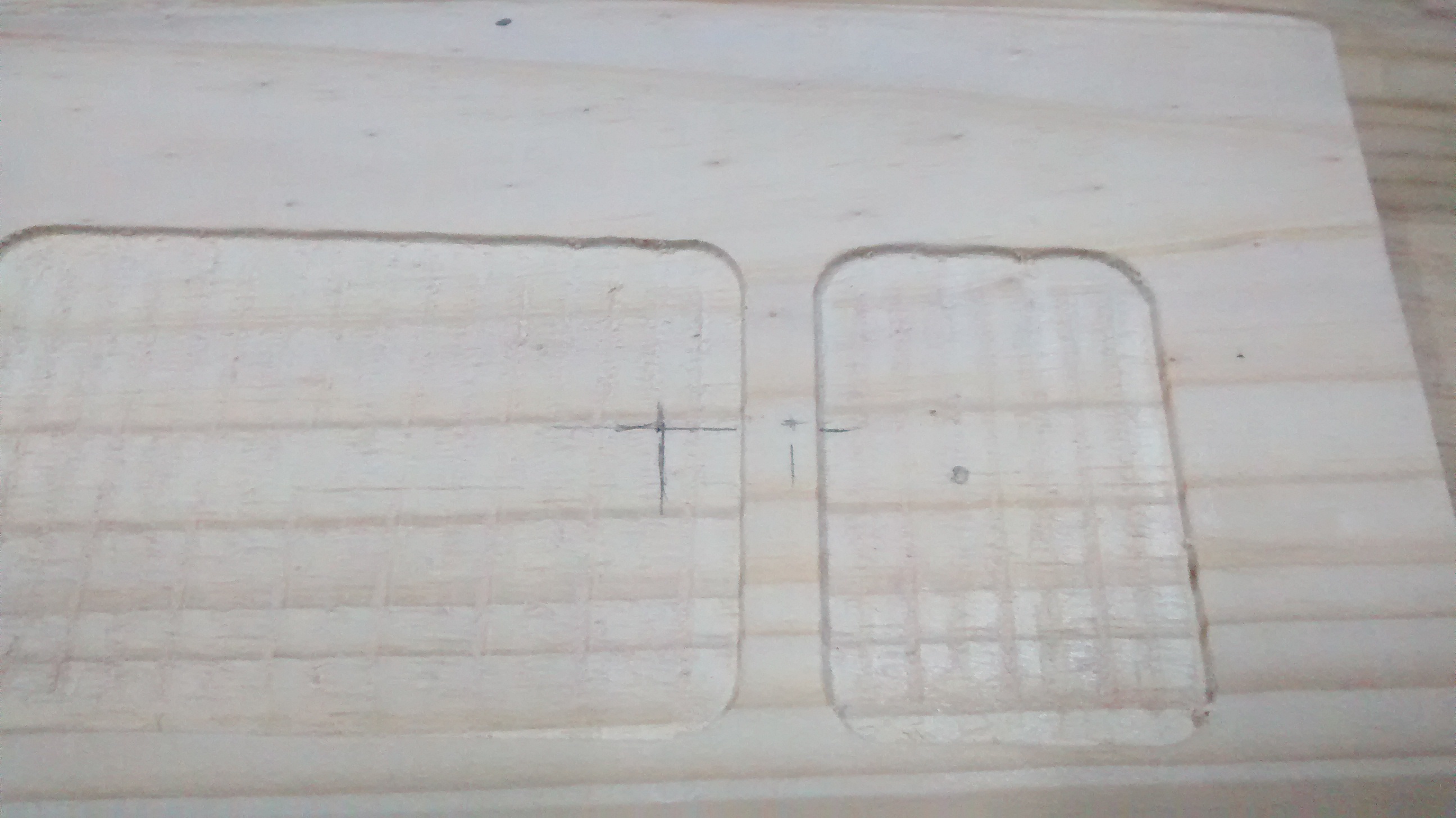
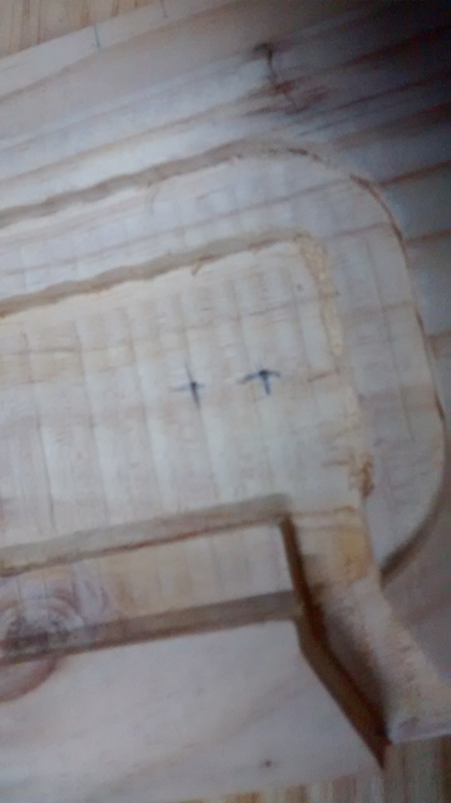
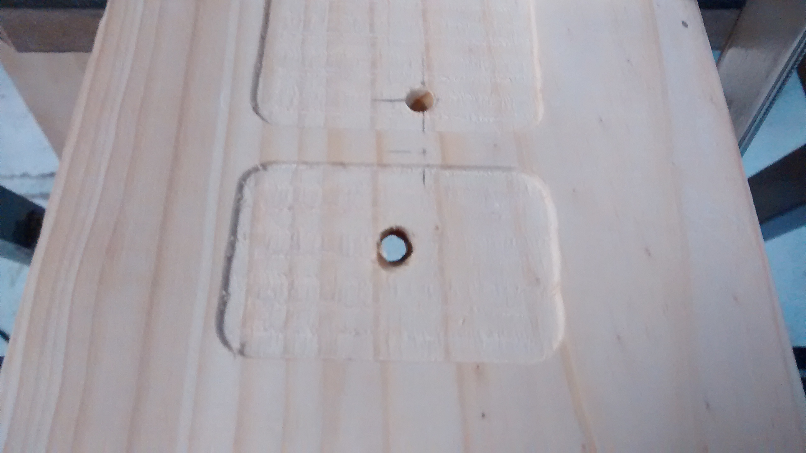
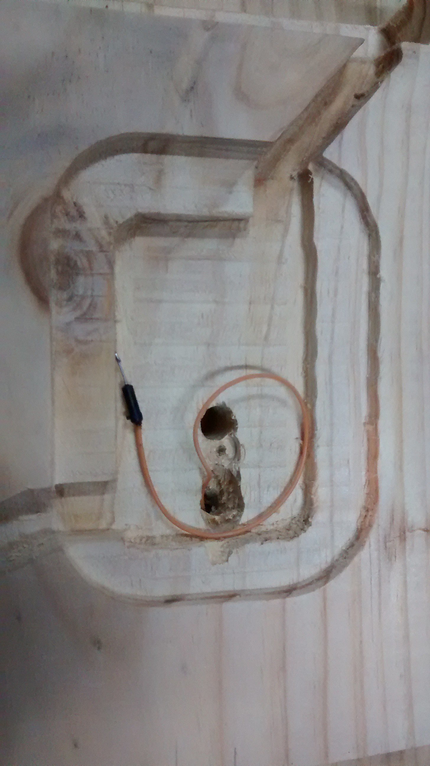
I had to move the wiring that goes to the LED arrangement and I also decided to make a cavity for them on the same milling process (previously I wanted to mill it with a manual router, but it wasn't practical).
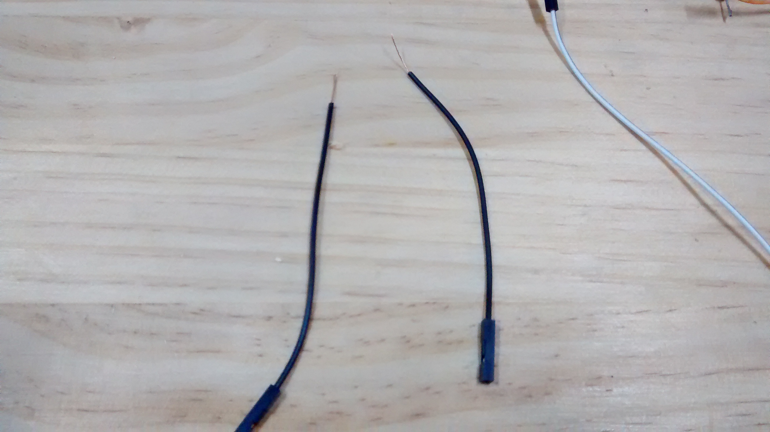
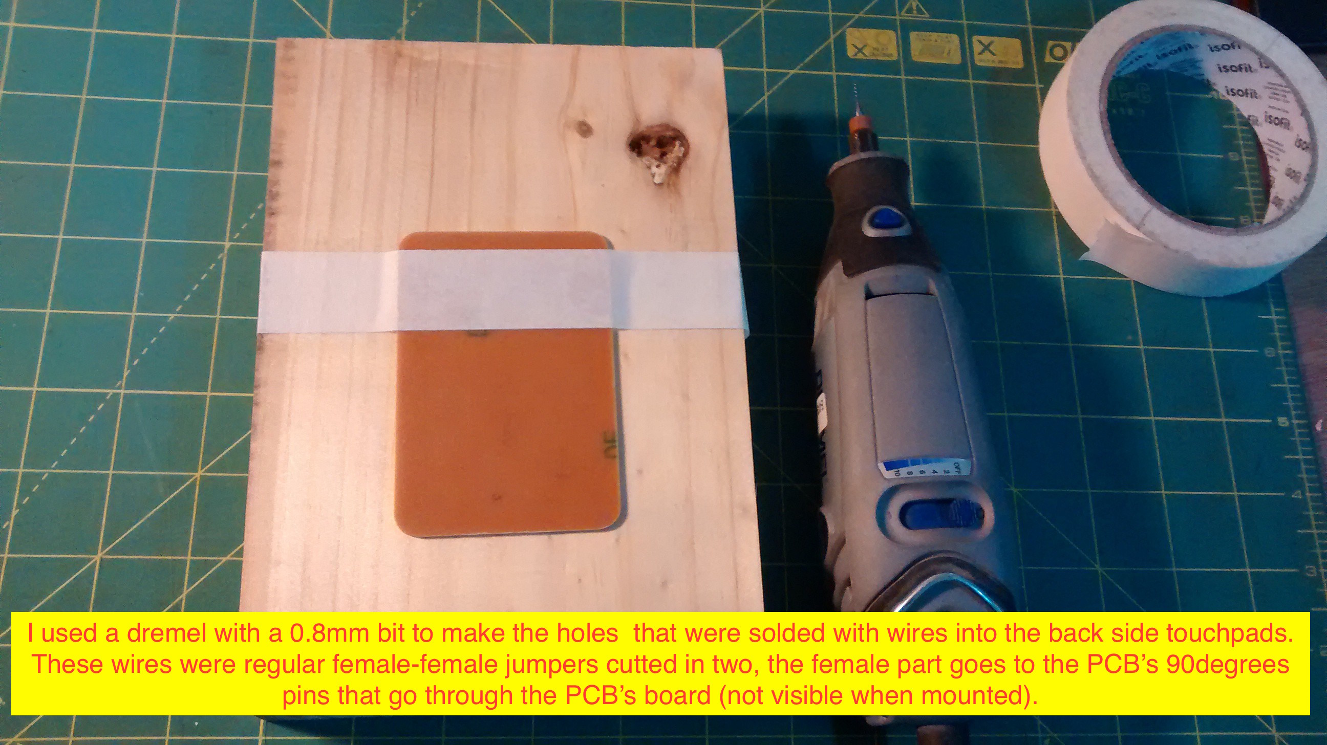
I also change the working method, now I'm trying to design, build, test and, just the, design the next component ... This is how I decided to finally build the touchpad buttons and to solve how to wire them to the board; here I noted that I had less room left on the PCB side than expected, so I decided that the PCB will have those 90 degrees pin headers.
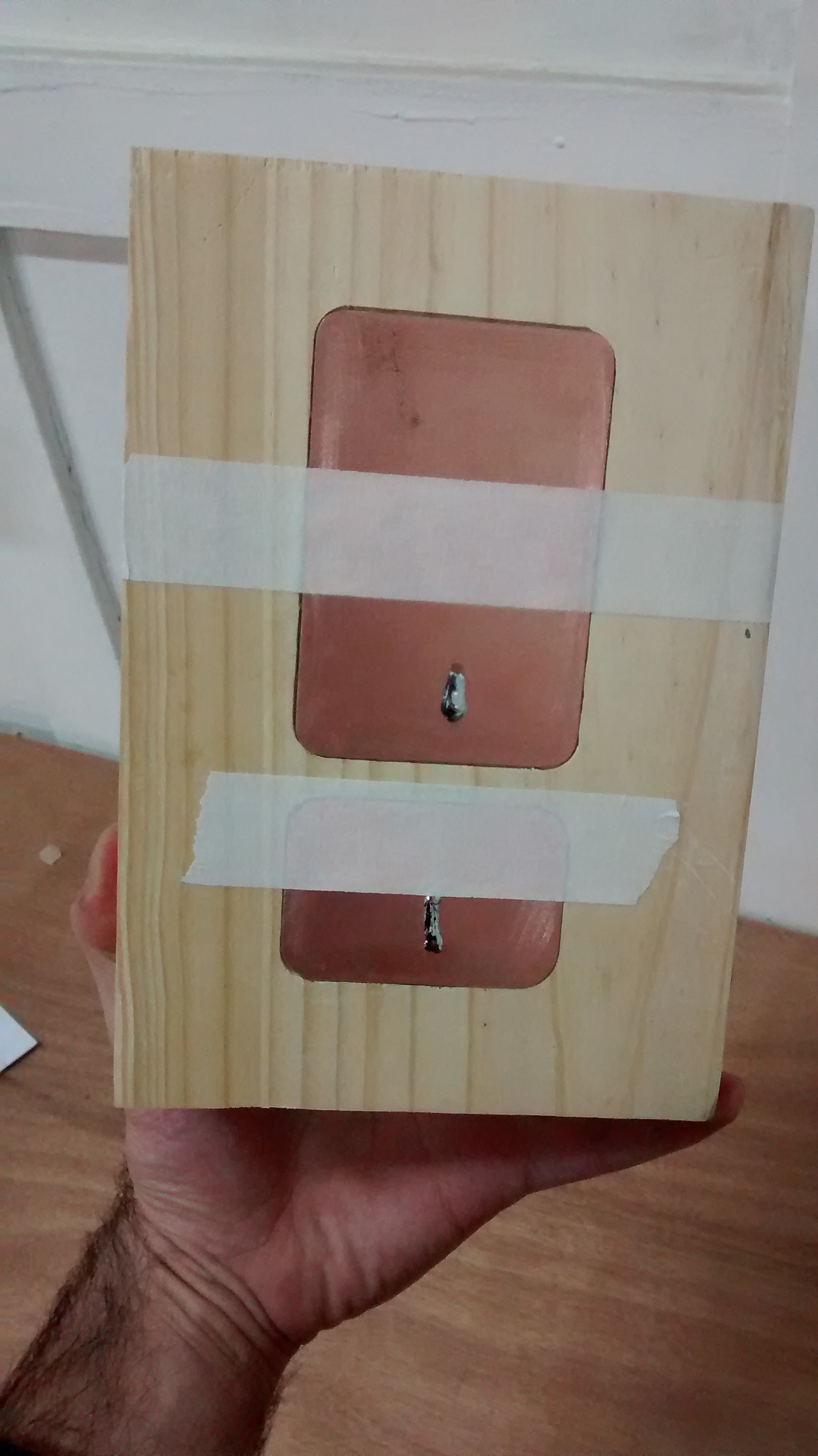
Regarding the buttons, I noted that is a lot easier to design them on Eagle instead of exporting their .dxf drafts from a CAD model, since there are less steps to build them (on a SRM-20 machine). On the previous iteration I exported the .dxf files and, since fabmodules doesn't handle that file format, I had to convert it to an image, paint it, adjust size (at this point it became messy), build, check and correct. So, summarizing, its easier to design on the withing the object machine's workflow instead of format transforming (note: luckily I could recycle the previous large button design, but I had to redesign the smaller one)
So finally the project is taking form, now I covered 2 major topics ... the electronics and the CAM part.
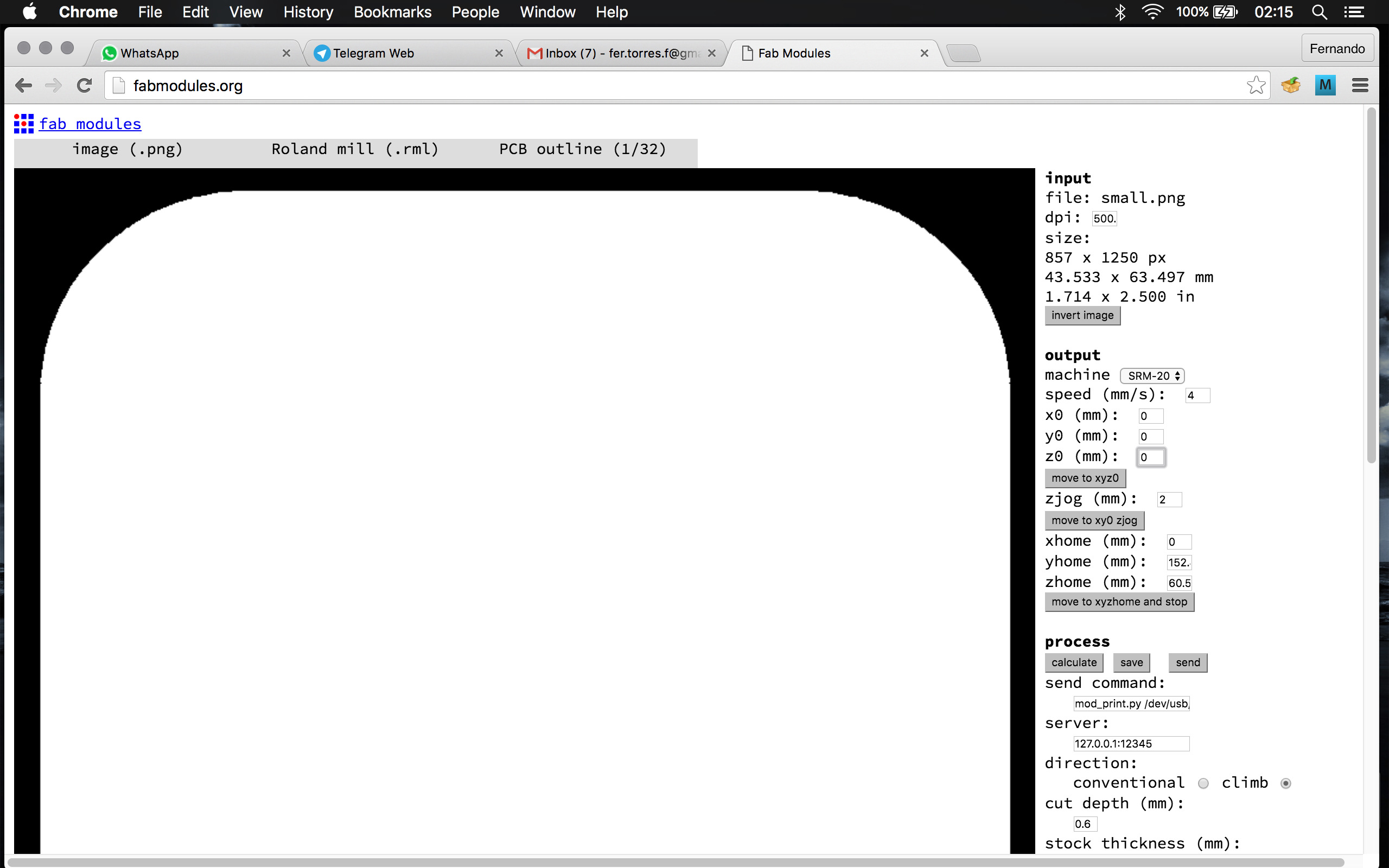
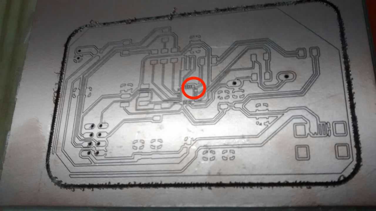
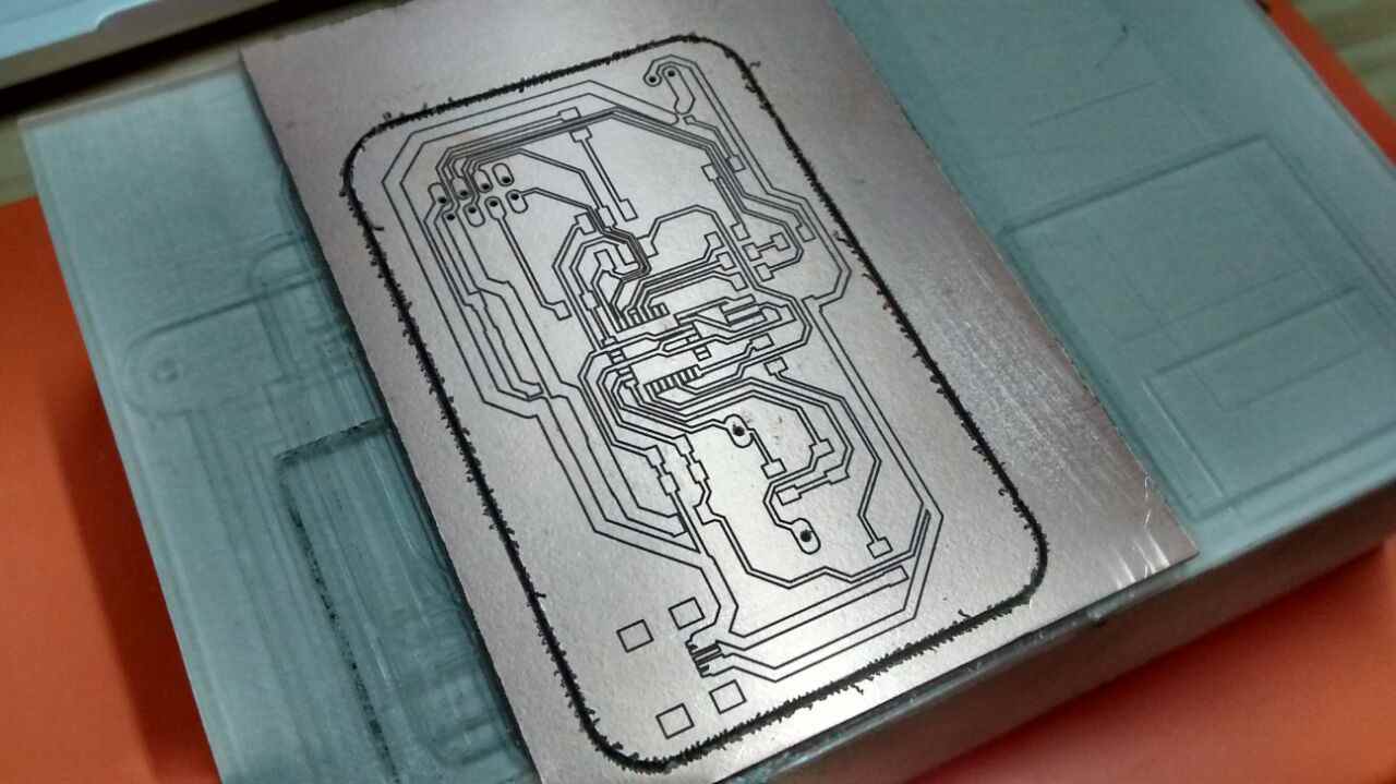
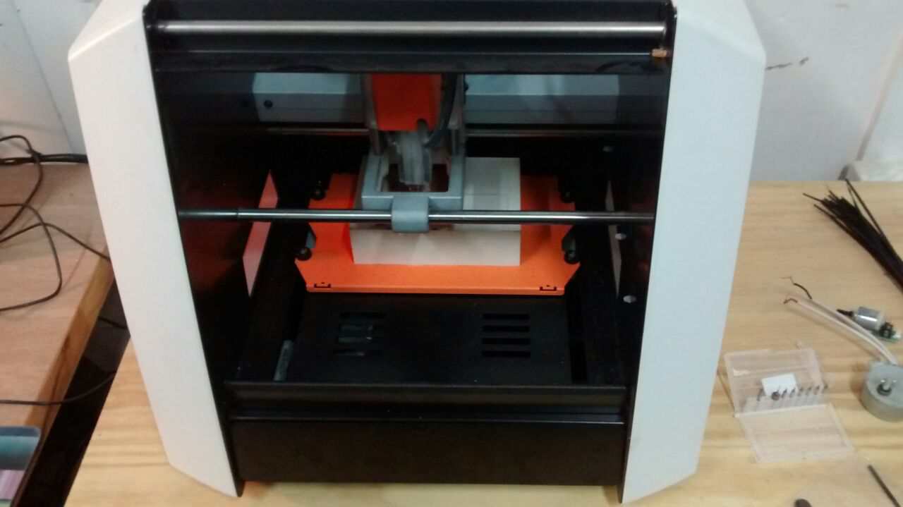
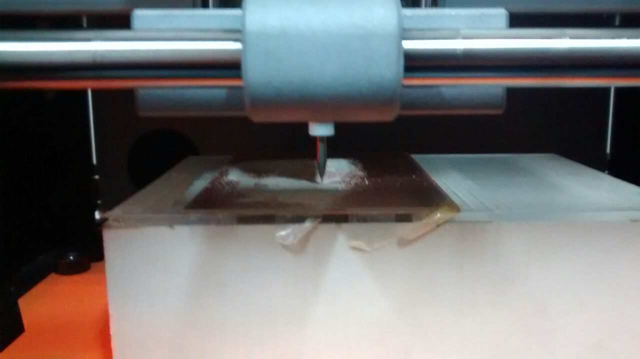
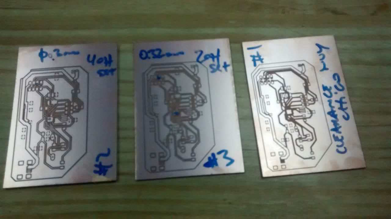
As I reported on the previous entry, I had problems milling the micro-controller on the PCB due to its tiny pin pads. So I went to the bit provider with the idea of buying a 0.2mm bit to try to mill those pads, but that bit was quite expensive (around 80USD); luckily the salesman suggested me to use a 30 degrees bit that lets you mill widths from 0.1mm to 0.3mm, so I could mill the board, not without having to intervine the PCB's image to clean some too close pads (widen the space between pads using the OSX's Preview tool).
 5
5
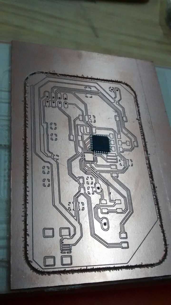
And here came the suprise ... I got a wrong 32 pad mega328 package on Eagle. I was sure to have seen on the data sheet that there was only one 32 pad package for this IC, luckily a friend (#391) was working with the same IC (with the correct package version) so after noting the error I could correct it quickly
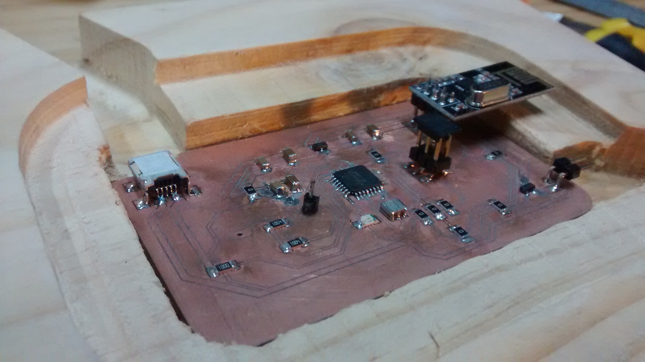
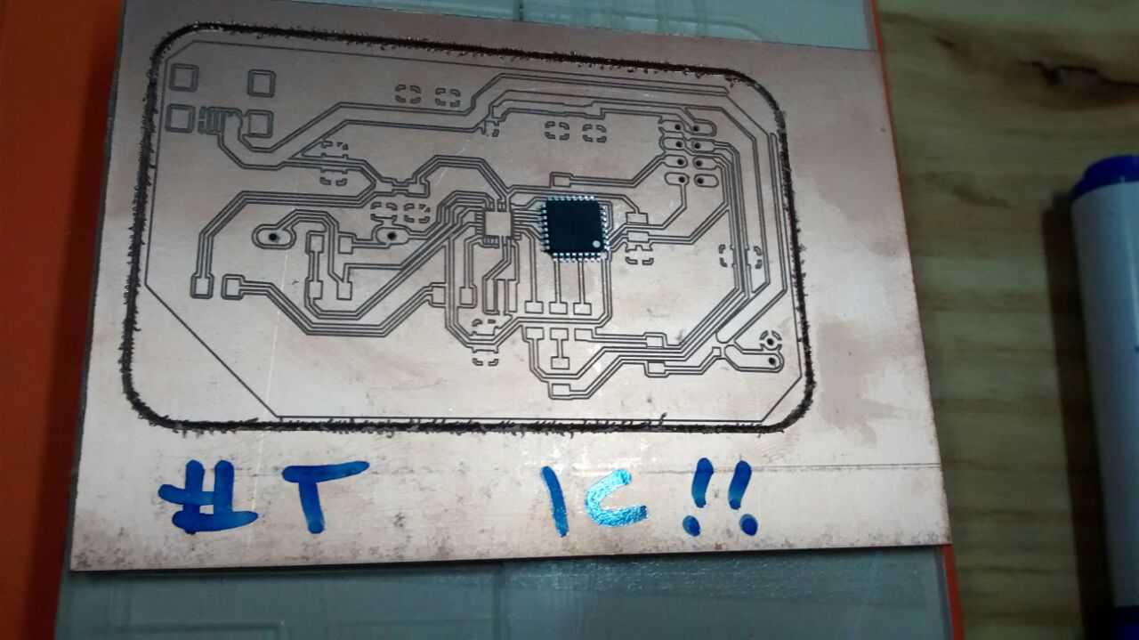
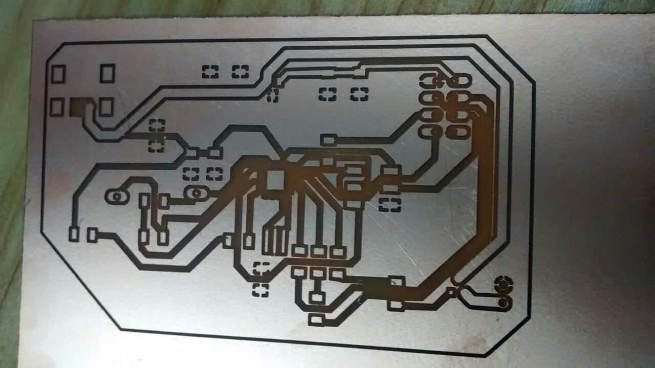
So now, with everything corrected, I could mill and populate the board as expected a week ago ... and, as it took some headaches to get the PCB, I took extra precautions while populating it and checked each component conection as I was soldering them.
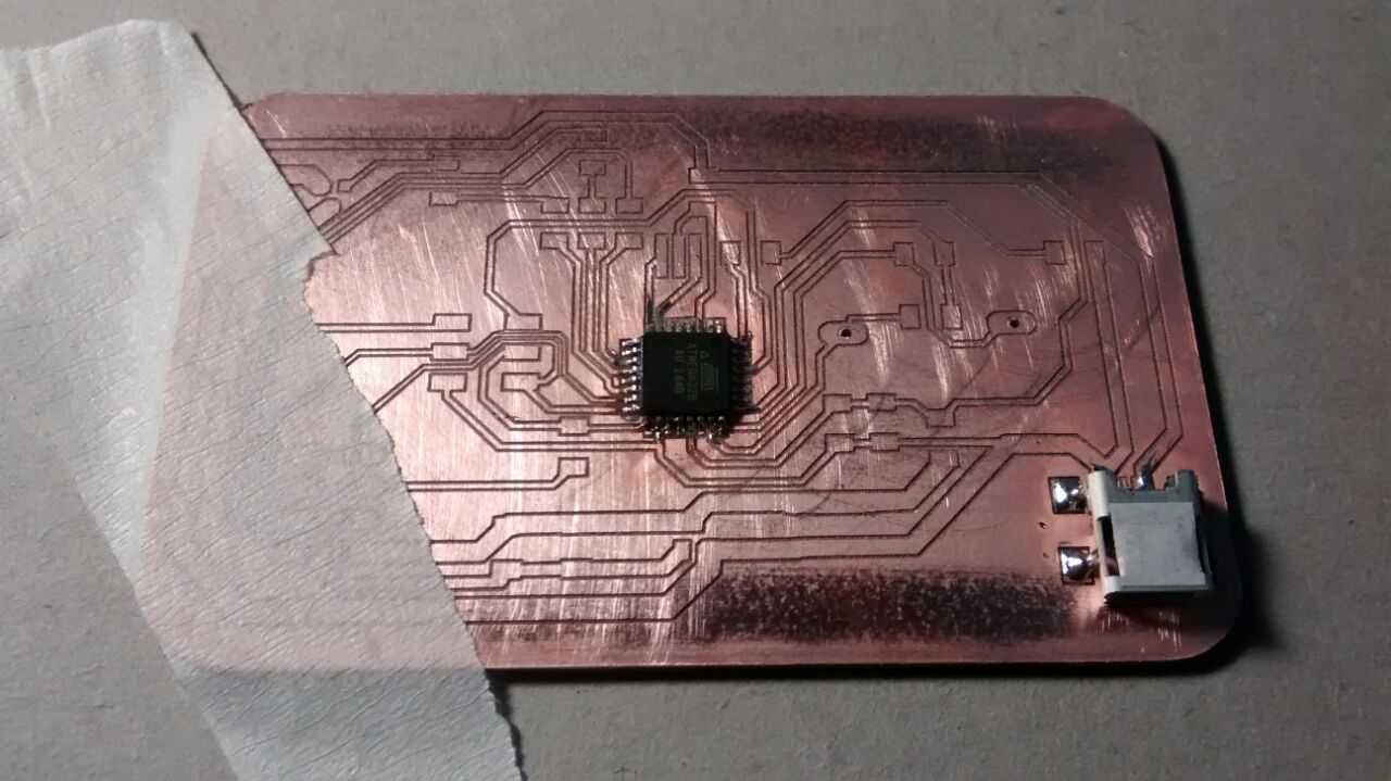
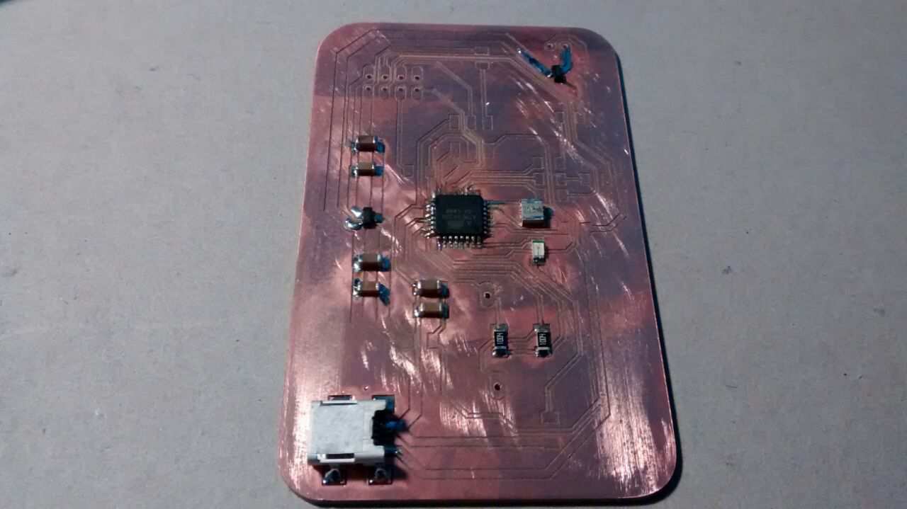
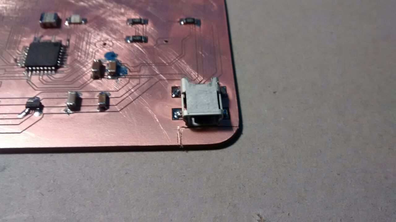
Here I noted that the USB port was too inside the board to plug the cord, so I simply trimmed the board to solve the issue.
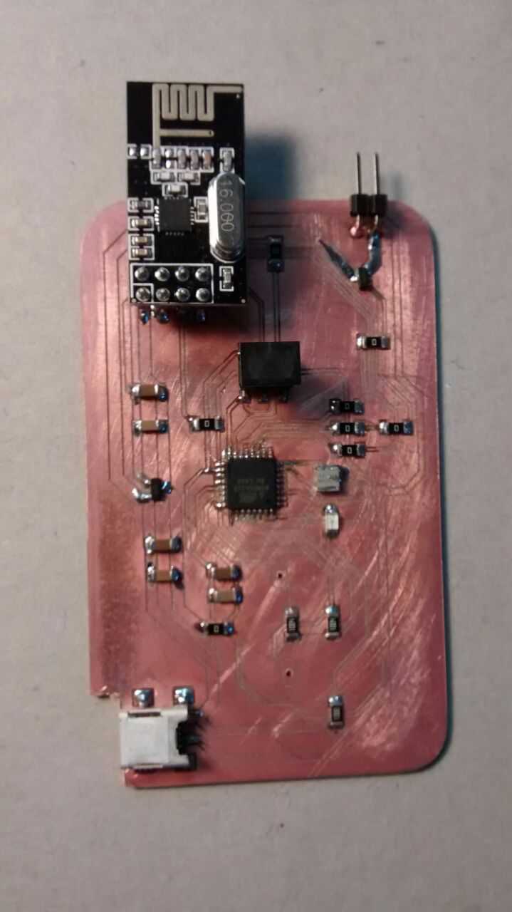
So finally I got to gather the electronics with the CAM. And more details appeared on the CAM side, such as no enough room to the USB cord and fitting issues between the acrilic cover and the wood block (this will be reported on the CAM assignment). Luckily there seem to be no issueѕ with the electronics. I also started to work on the illuminating system.
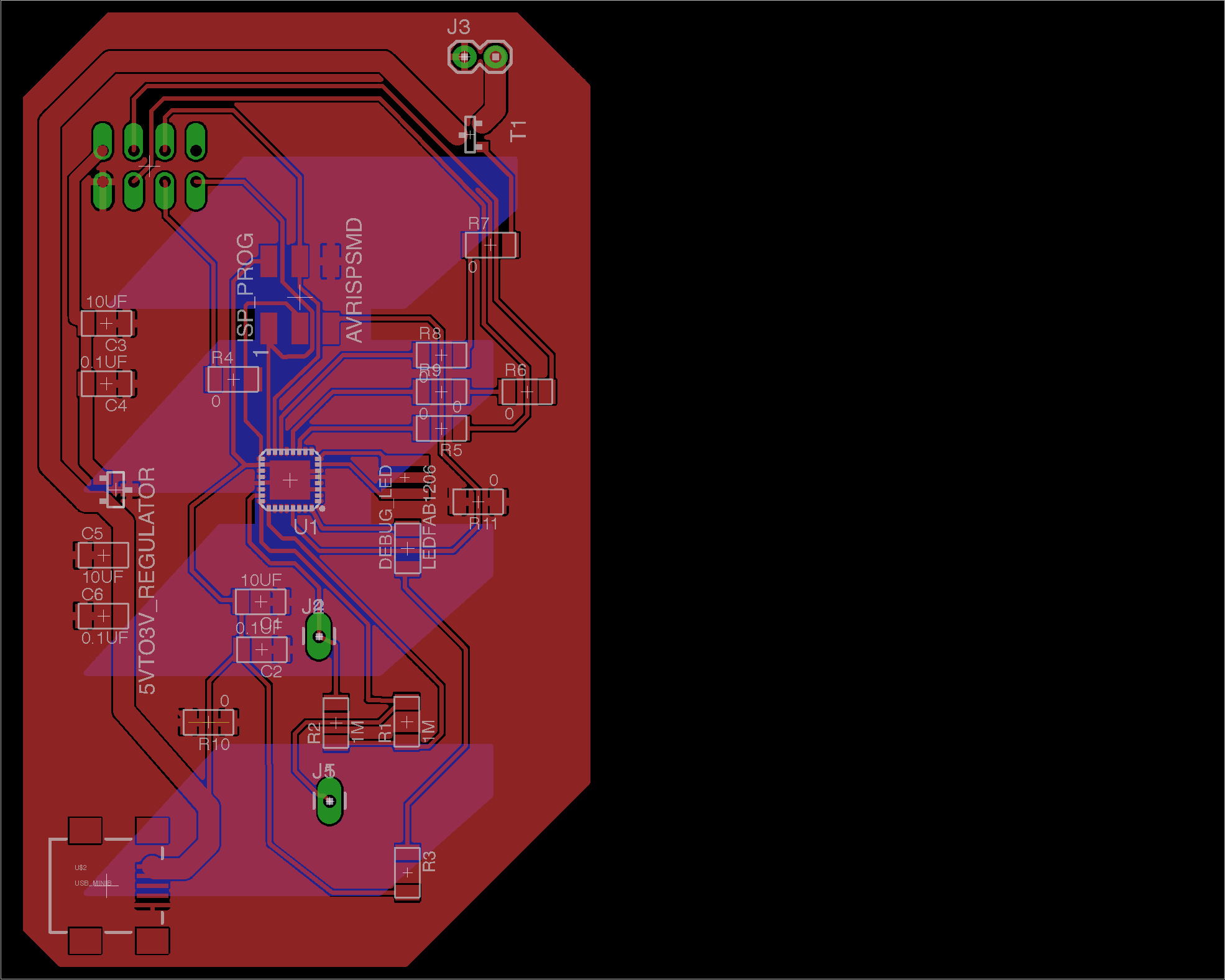
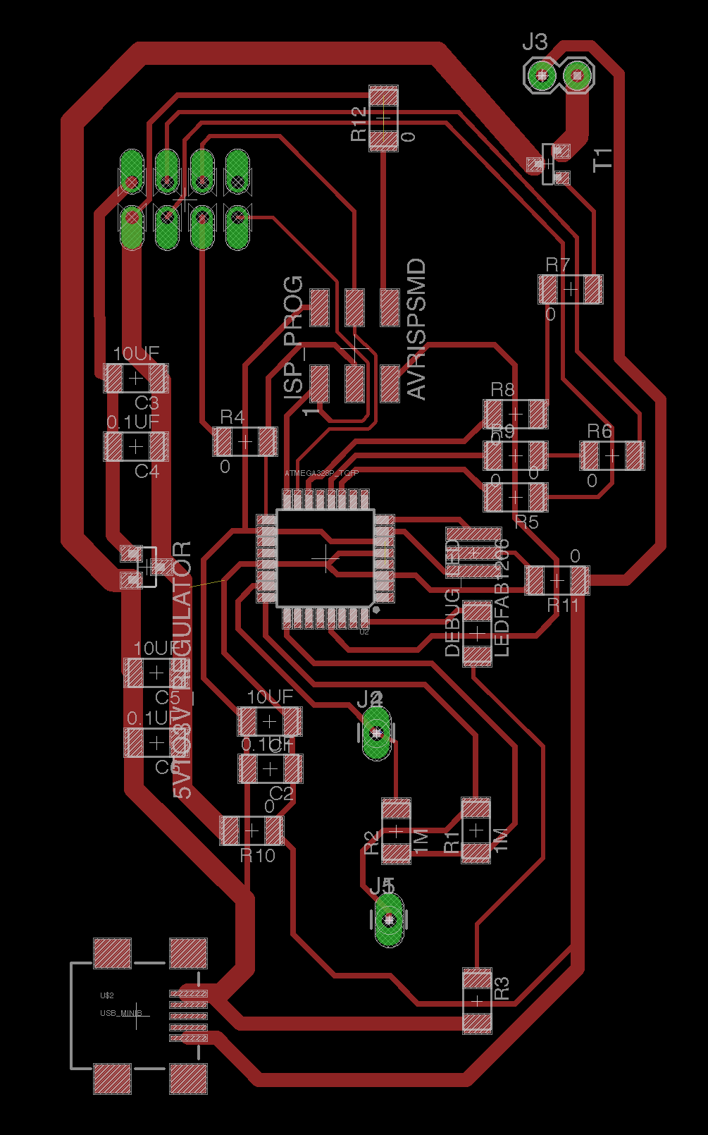
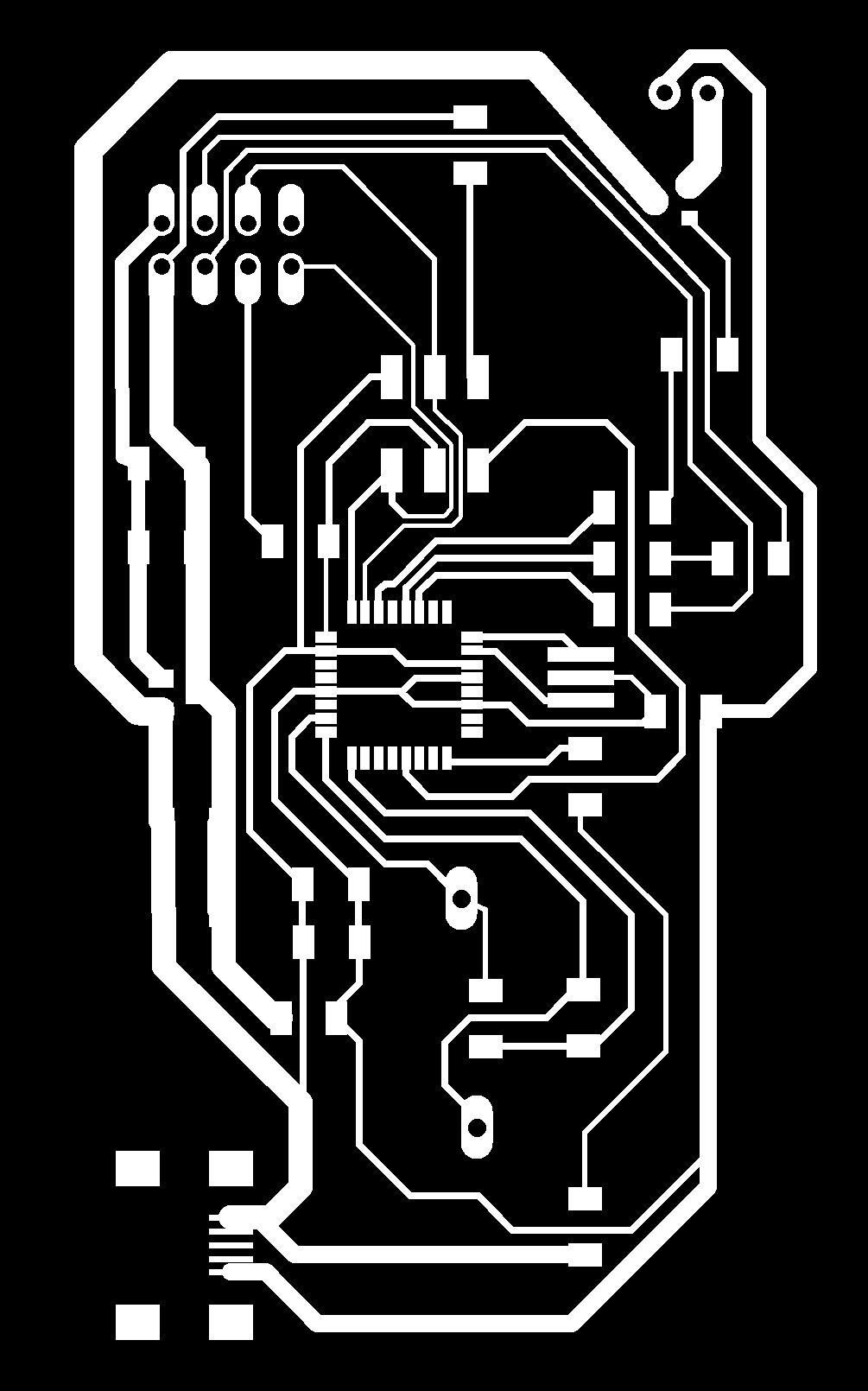
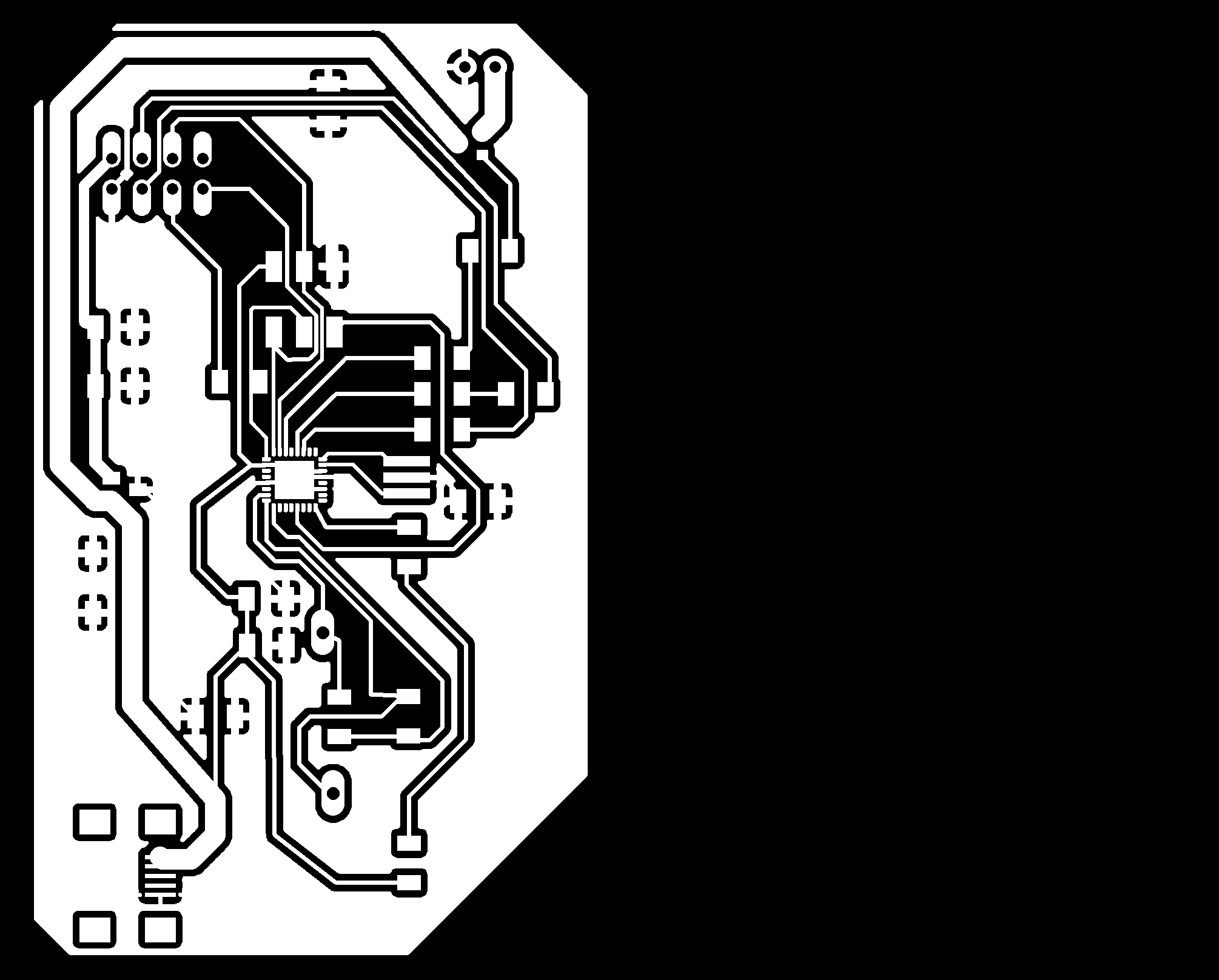
Here are the images to reproduce the electronics: board, traces, holes and contour. Here are the schematics and board (EAGLE files).
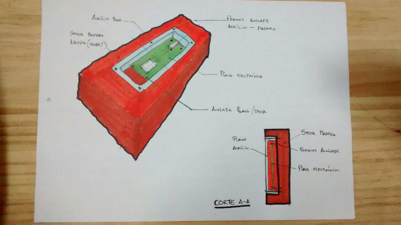
After reviewing again the project I realized that the electronics are the starting poing to define the rest of the project's dimesions. I also decided to simplify even more the lamp by changing the overall shape to a simple wood block (without any moving parts) with the touch pads exposed on one side and the electronics embeded into the wood covered by a traslucent acrilic on the other. The LED lights will be on the top edge of the wooden block.
In the previous entry I said that I'd go to work on the electronics, and so I did. I worked on the capacitive touchpad and started designing the final board.
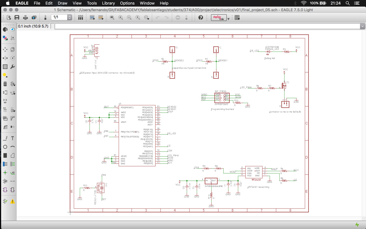
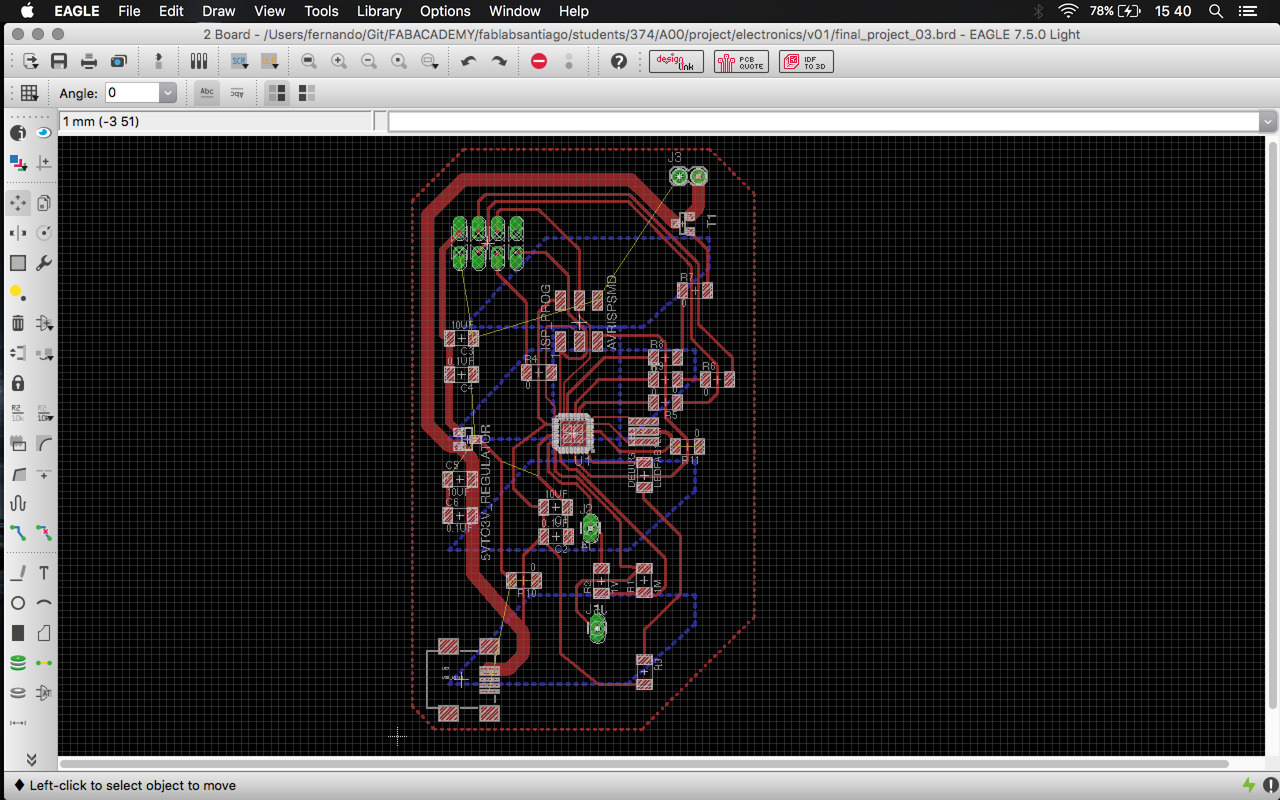
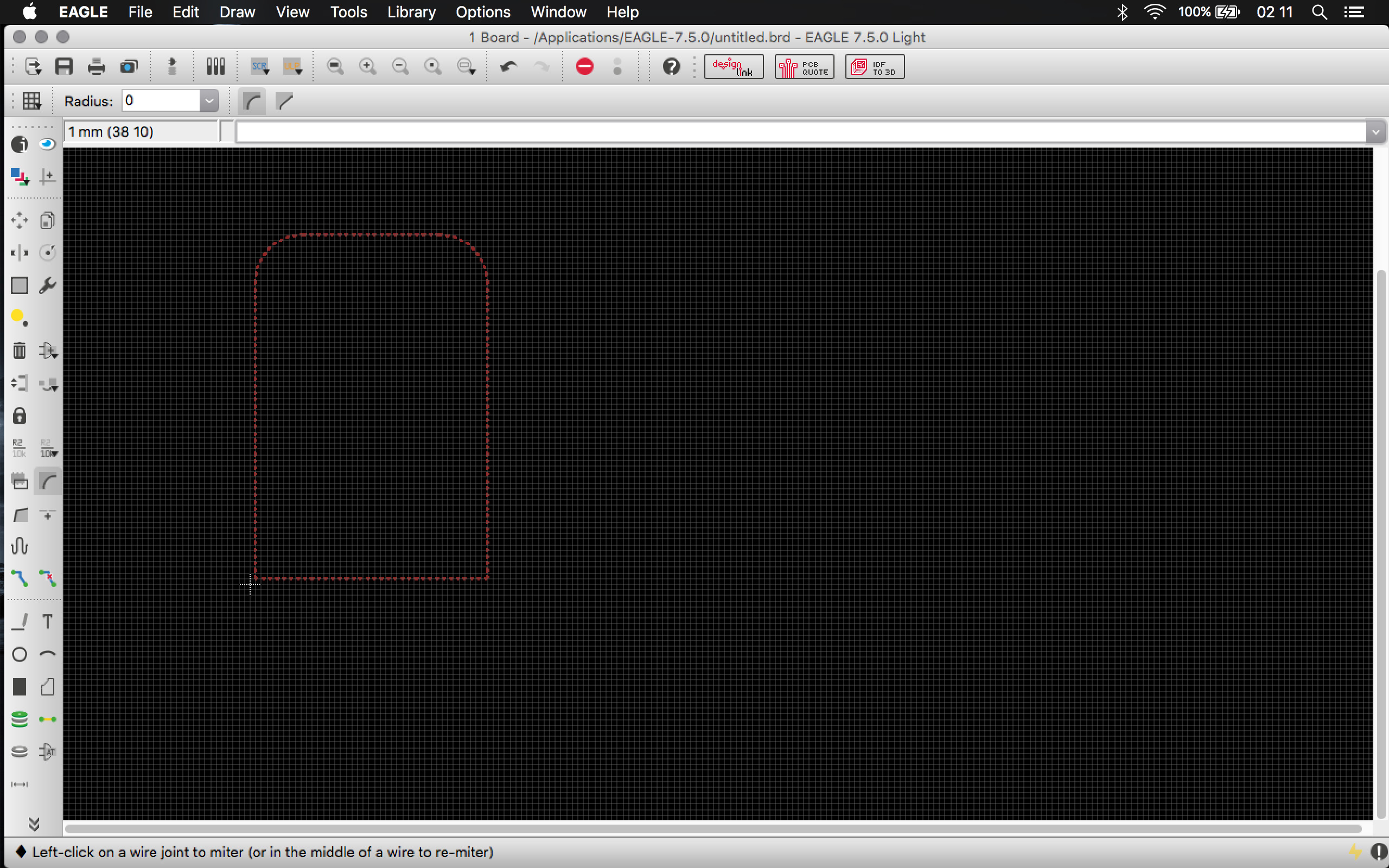
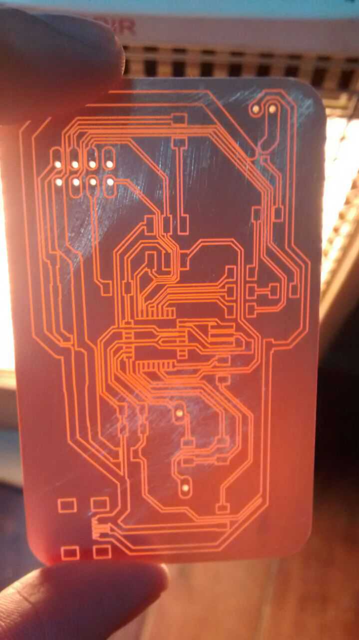
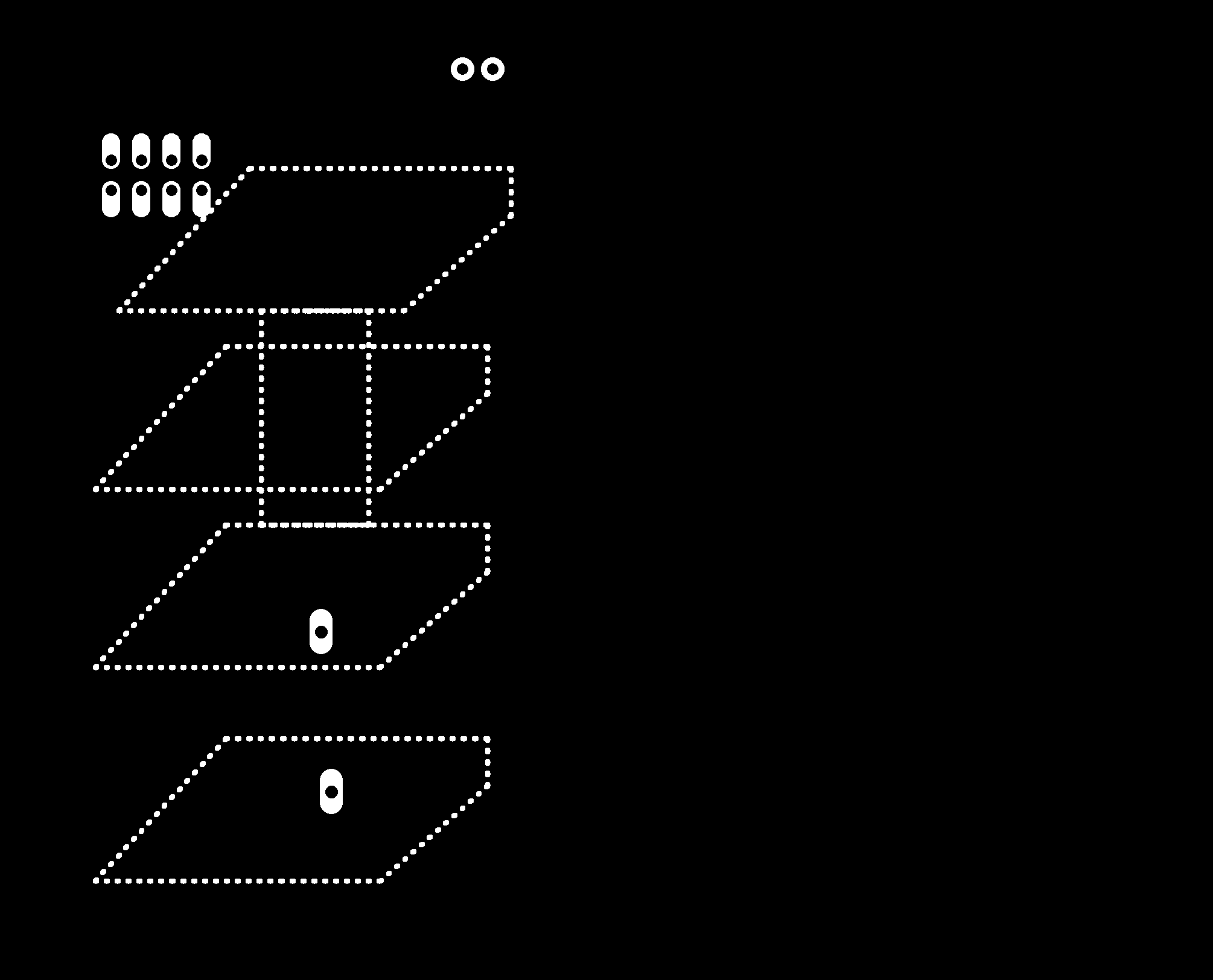
Most of the design process went well, but after I added the touchpad buttons on the second layer to make the holes fit I could only make the PCB top's layer ground (as explaied here). This is shown on the next image; after saving and opening I could not reproduce the layer grounding procedure. Anyways, I got to export the .png images to use fabmodules. Here are the links to these images: top traces, top holes, top dimension, bottom holes and bottom dimension. So next are the results of the PCB manufacturing:

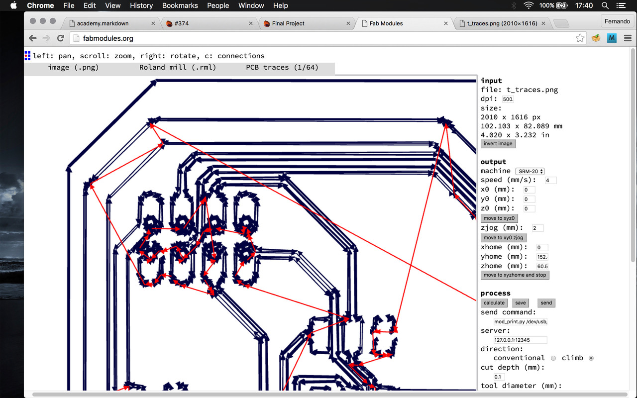
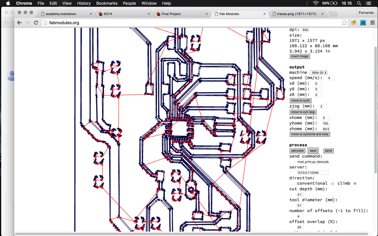
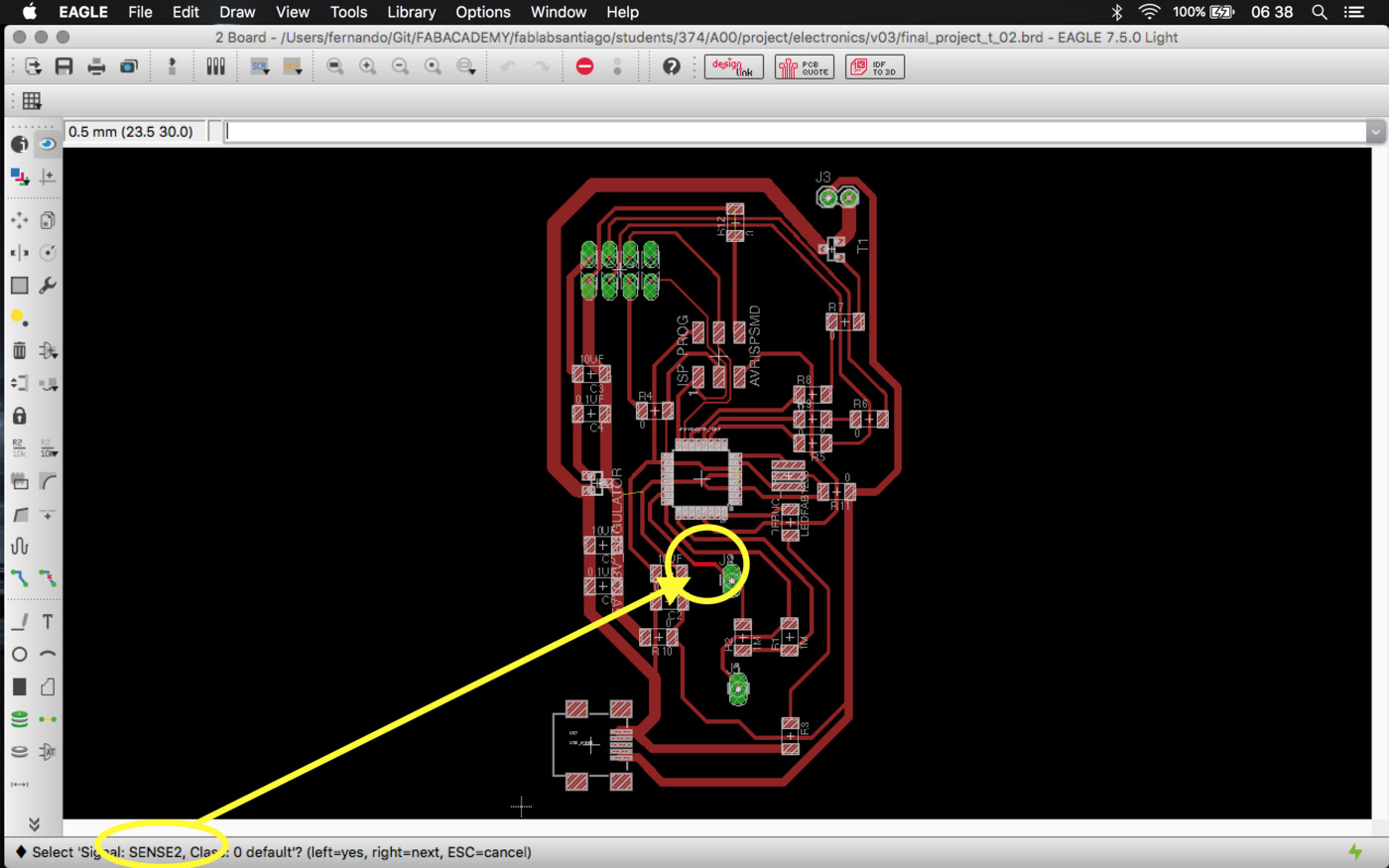
It turned out that I couldn't mill the Mega328's pins, even after modifying the GND isolation on Eagle (to widen the space between tracks; this actually solved problems on other parts of the PCB), modifying the track's widths, bit diameter (to force fabmodules make the bit mill in spaces it shouldn't fit) and reducing the offsets.
The next step is to reduce the bit diameter on fabmodules until it just goes through the microcontroller's pins and leaving only 1 offset. If this doesn't work I'll try with a 0.2mm bit (I yet have to buy it). And if this doesn't work either ... I'll redraw the PCB with other(s) microcontrollers (it might be easier to have a dedicated IC to some tasks and communicate information among them).
Here is the component list for the current PCB version (v01).
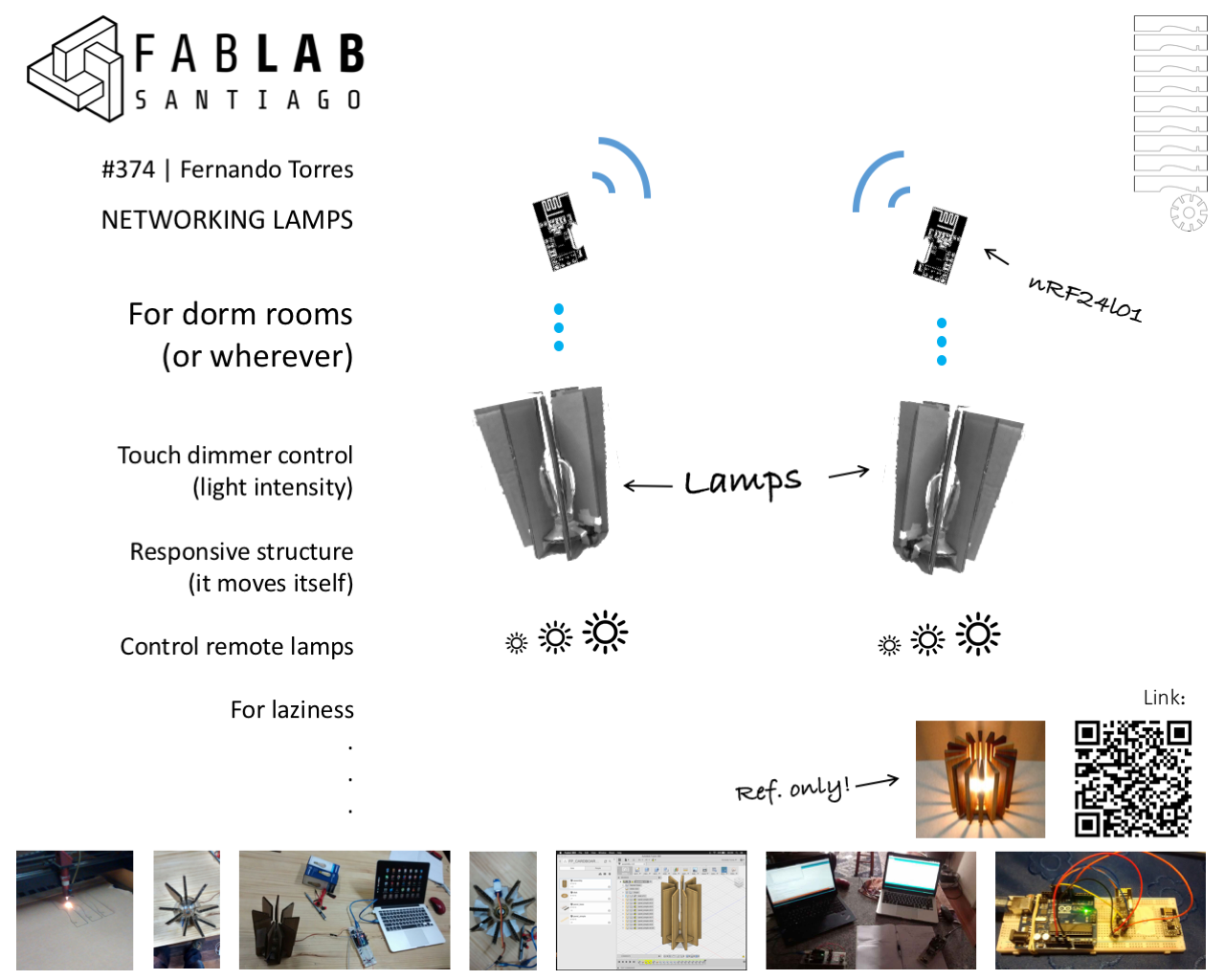
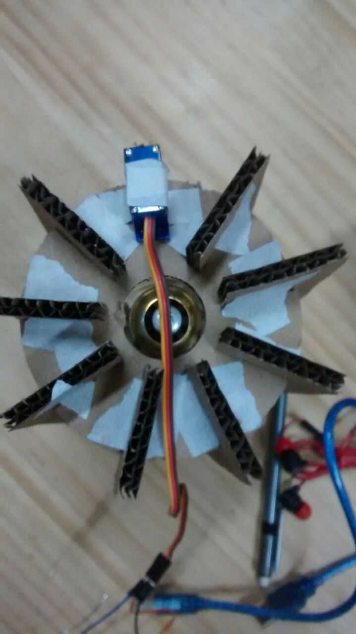
So, as part of my presentation (17/06) I worked on a basic prototype and reviewed a lot my project's proposal. Here are the slide and video I showed up.
Some of the conclusions I made after this first iteration are:
-
About the networking I'll only use a "1 to 1" network, I'll discard the mesh network due to time efficiency. However, this feature might be included later via firmware update since is only a library issue, at a hardware level I'll be limited to only 1 extra button instead of the 2 first proposed, but that can be worked around too through gestures (touching the buttons many times in intervals to generate behaviours).
-
On the hardware side I decided that there will be only the slide touch pad and one touch button. This helps me to think on the firmware's side that the single button will only activate the communication to the second lamp to transmit the slider intensity value.
-
Other decision on the hardware side ... after looking for alternatives I found this kind of bulbs, which are rather fancy, stylish and provide the warm light I want to my lamps. So, after looking for local providers (luckily I had one a couple of streets from the Fab Lab). BUT this local provider didn't have exactly the same bulbs ... these ones a AC bulbs, not LED DC bulbs ... this conditions the power source system. Now I have to consider a 5V voltaje transformer and a dimmer to modulate the light's intesity. Here, here and here are a links of projects that do this, but with other components, I need to check components availability.In fact ... I don't have at hand the components to dim the AC bulb ... so I wasted money with those fancy bulbls and back to the LED lamps. Anyways, this is better in many ways, now I can simplify a LOT the electronics design and the power sourcing (not dealing with AC current anymore); this also leaves a lot of room to play with the lamp geometry.
Finally, this is the material generated to the presentation:
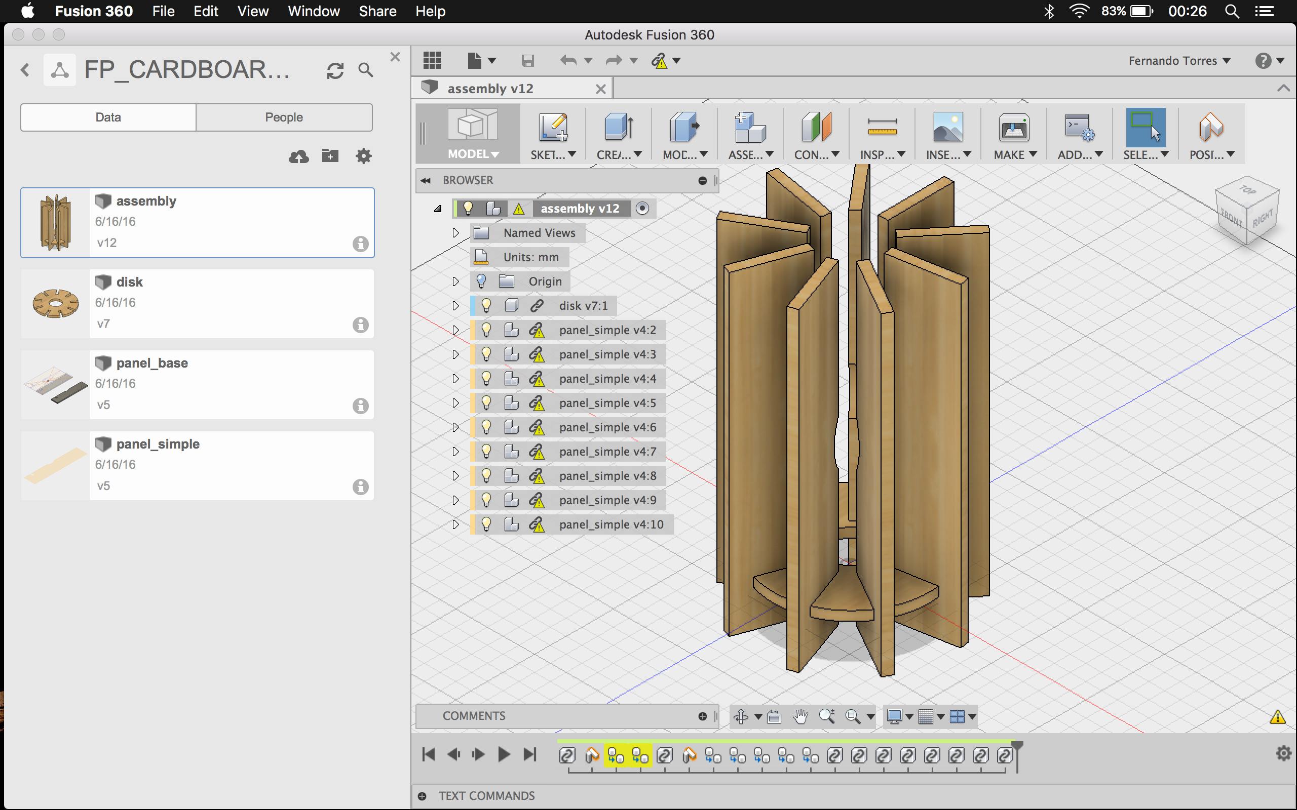
And here is the Fusion360 shareable link to the 3D model. It is a very humble 3D version of the lamp, but by laser-cutting it I could actually touch the lamp and verify, for example, the moving panel functionality and to estimate the room it needs to don't hit its neighbour panels, and to actually check if it made sense to move the panel ... it doesn't seem to be that necessary, but is too cool to leave it out.
⋮Now is time to dig into the electronics, starting with the touch capacitive interface reference project (seemly the most difficult part of the project along with the networking). With this my intention is to cover both the interfaces and the input devices assignments. After this I should concentrate on the dimmer and powering parts of the electronics.
I'll also start to buy the materials (sockets, wires, wooden panels, etc.) to build the project to start 3D modelling too.
So, after analysing my assignment's status I realized that the former idea didn't covered enough topics, so I decided to change my final project to a set of dorm-room lamp set.
This lamp set should have the next features:
Output devices:The lamp bulbs (or led, yet to be defined) will act as the output device, since the light intensity should be variable.
Input devices:The main goal of this project is to provide these lamps with a touch interface; ideally I'll have one touch panel to handle the light intensity and (optionally) a couple of touch buttons to control the overall system behavior, i.e. one lamp should be able to modify the light intensisty of all the set, eventually even control each of the other lamps of the set.
The references I'll use to this part of the project are Matt Blackshaw's input devices assignment and Matt Keeter's multi-touch device, both appeared in the "Input Devices" class.
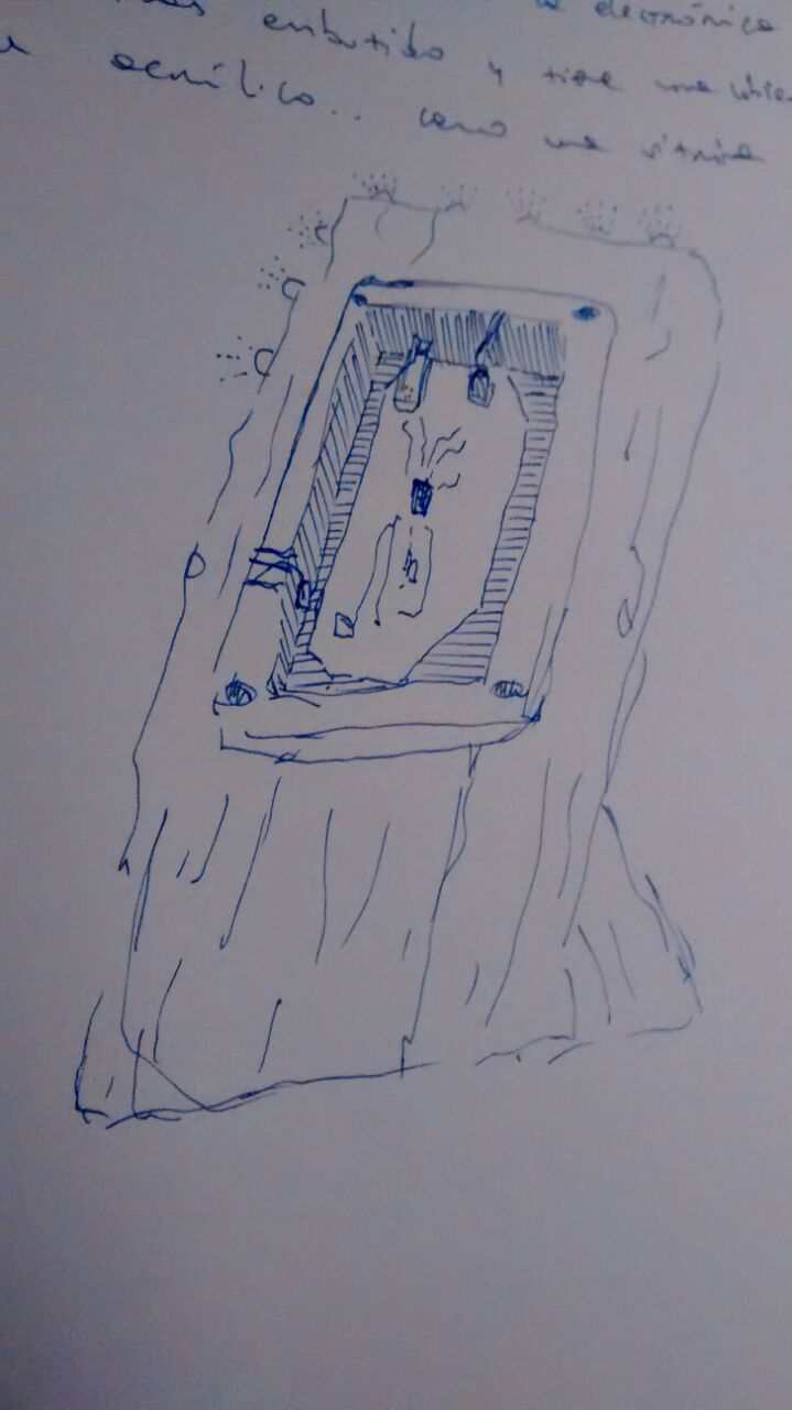
Oh! I forgot to mention that I want the electronics to be visible, I'm bored of people arguing that electronics should be hidden and be "the blackbox magic". I still need to look for some traslucent resin with which I'll cover the electronics.
Big something bigWell, at first I thought of building a standing lamp, but in this iteration I'll stick to small dorm-room lamps (to test the networking I need more than 2 devices). The manufacturing process is the same, so it should suffice to probe the workflow.
NetworkingNetworking is, maybe, the most attractive feature that this project will offer; the idea is that you could control a set of lamps by manipulating only one of them in the network and that you could add an unrestricted number of lamps to the system. Sincerely at this point I'm not sure how to set up the communication system, it should be wireless for sure.
InterfacesThe project itself won't have any graphical interface, but I'll need to have one to setup all the touch sensing system. The most probable thing I'll do is to only rebuild the "input devices" reference projects, since both have their own interface.
CompositesNot sure yet if I'll be able to include some composite component into the project.
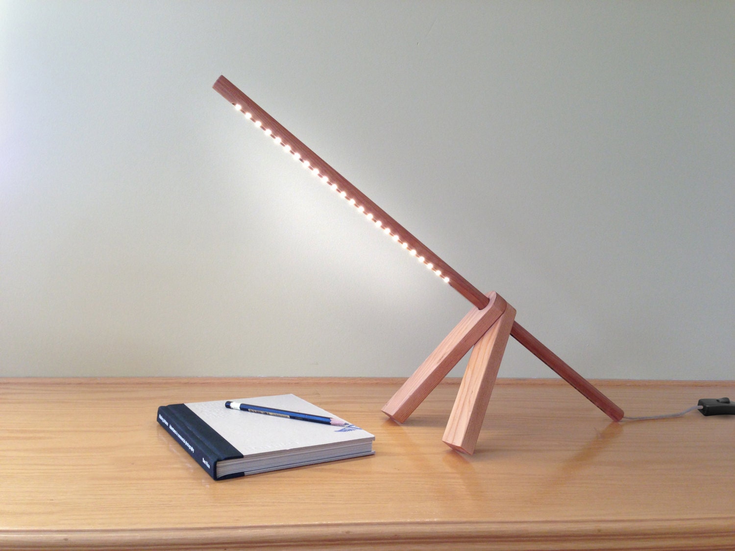
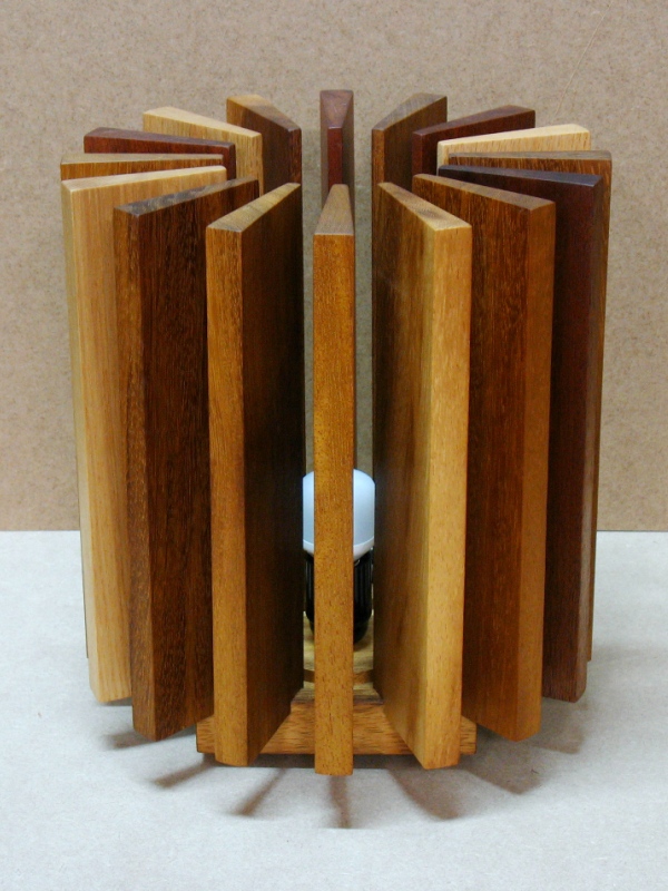
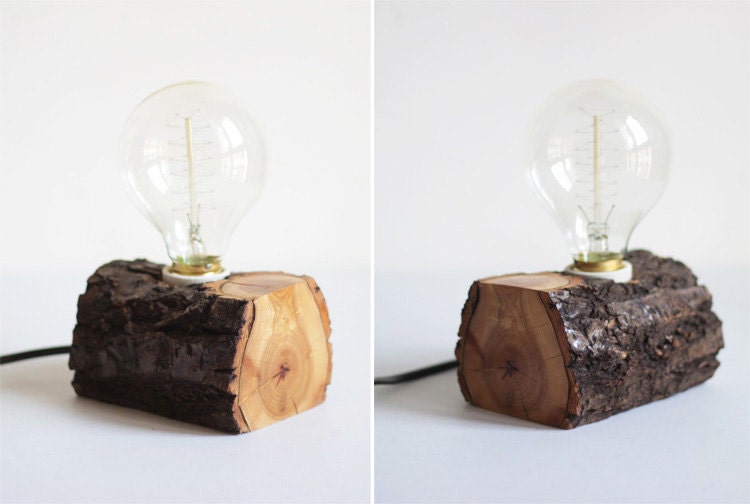
Anyways, here are some reference lamps I like:


Here I'm leaving the links to all the reference projects I'll need:
On the electronics:
-
Dimmer: Francisco Camacho's, Instructables, DIY Hacking - Capacitive touchpad: Matt Blackshaw's, Neil's step response, Matt Keeter's, Instructables, Santi Fuentemilla.
- Programming
- Servo motor: Neil's servo motor
- Powering
- Networking: My networking site, tutorial of AVR and nRF24l01