Assignment 13
Networking
Assignment:
Design and build a wired and/or wireless network connecting at least two processors.
Learning outcomes:
- Demonstrate workflows used in network design and construction
- Implement and interpret networking protocols
Have you:
- [ ] Described your design and fabrication process using words, images and screenshots
- [ ] Explained the programming process(es) you used
- [ ] Outlined problems and how you fixed them
- [ ] Included original design files and code
Index
The original idea was to implement a mesh network using the nRF24l01 module among the final project's lamps to be able to add whatever number of lamps to the system, but looking at the time left I'll only stick to a simple 1 to 1 network (I actually want to build only two lamps in this iteration). Anyways, I'm not discarding the mesh at all, just posponing it.
So the plan now is to be able to send commands from one Arduino to other and from the second to the first. With this completed I can focus on other parts of the final project.
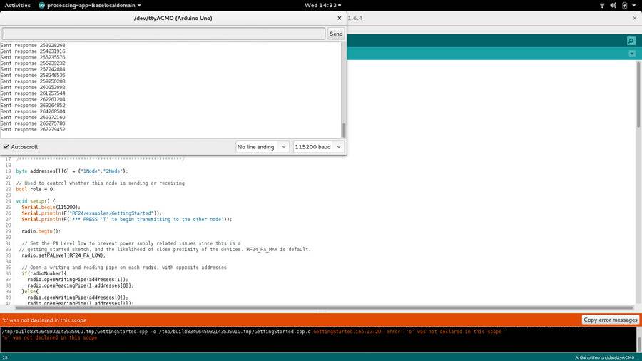
By looking at the Arduino's Examples > RF24 > GettingStarted
code I checked that if I modify the "Change Roles via Serial
Commands" part I can include some kind of outer actuator (a button
or potentiometer to test; a capacitive touch surface to the final
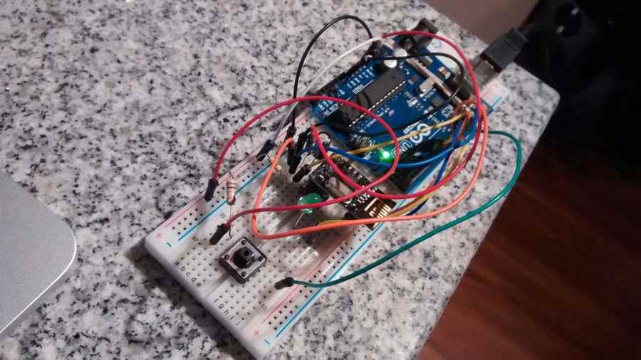
project). So, as a second baby step I'll try to get one button and
one LED on each Arduino, so that when I press the button on one
board the LED on the other will turn on.
So here is the code, I got to measure the time the button is pressed in one board and send the value to the other, turining on the LED during the measured time.
So this is the second baby step; a third one might be to "stream" values from one board to another, to give a sense of real-time interaction.
As part of my final project I need to be able to send commands to through a network composed by lamps. After a little research and suggestion from friends I found the nRF24L01 module, which has some mesh networking libraries available to Arduino, thus compatible with our AVR microcontrollers.
So, in order to "spirally approach" to my final project's goal, I'll first try some exercises. Following these instructions I'll proceed to setup a mesh network doing baby steps. The first step is to install the RF24, RF24Network and RF24Mesh libraries from the Arduino Library Manager. Here are the corresponding repository links to each library (to use afterwards when programming my microcontroller, NOTE: CHECK THIS LINK to more on AVR+nRF24l01): RF24, RF24Network, RF24Mesh.
In summary, these are the steps to work with the module in Arduino (taken from here):
" ...
1. Configure and test the hardware using examples from RF24 and RF24Network prior to attempting to use RF24Mesh. In Arduino IDE:
File > Examples > RF24 >
                  GettingStarted
2. Once testing is complete in the Arduino IDE:
File >
                  Examples > RF24MESH
                  > RF24Mesh_Example
3. Once configured and running, the Master Node will begin to assign addresses to the sensor nodes, which will find their way onto the network, and display incoming data from the sensor examples. Usage is very much the same as RF24Network, except for address assignment and network management.
..."
⋮Resuming, I went to the first example and to my surprise I found no clear wiring indications, it says ...
              /* Hardware configuration: Set up nRF24L01 radio on SPI bus plus
              pins 7 & 8 */
              RF24 radio(7,8);
So, what are the connections? What is the SPI bus? By reading this article I found out that the SPI bus is actually the MOSI, MISO, SCK, SS (Slave Select ~ RST), VCC and GND we used when programming through ISP our AVR microcontrollers (just connecting dots). In this site they confirm this on the "Pinout and connections to Arduino" table. So, the connection are these:
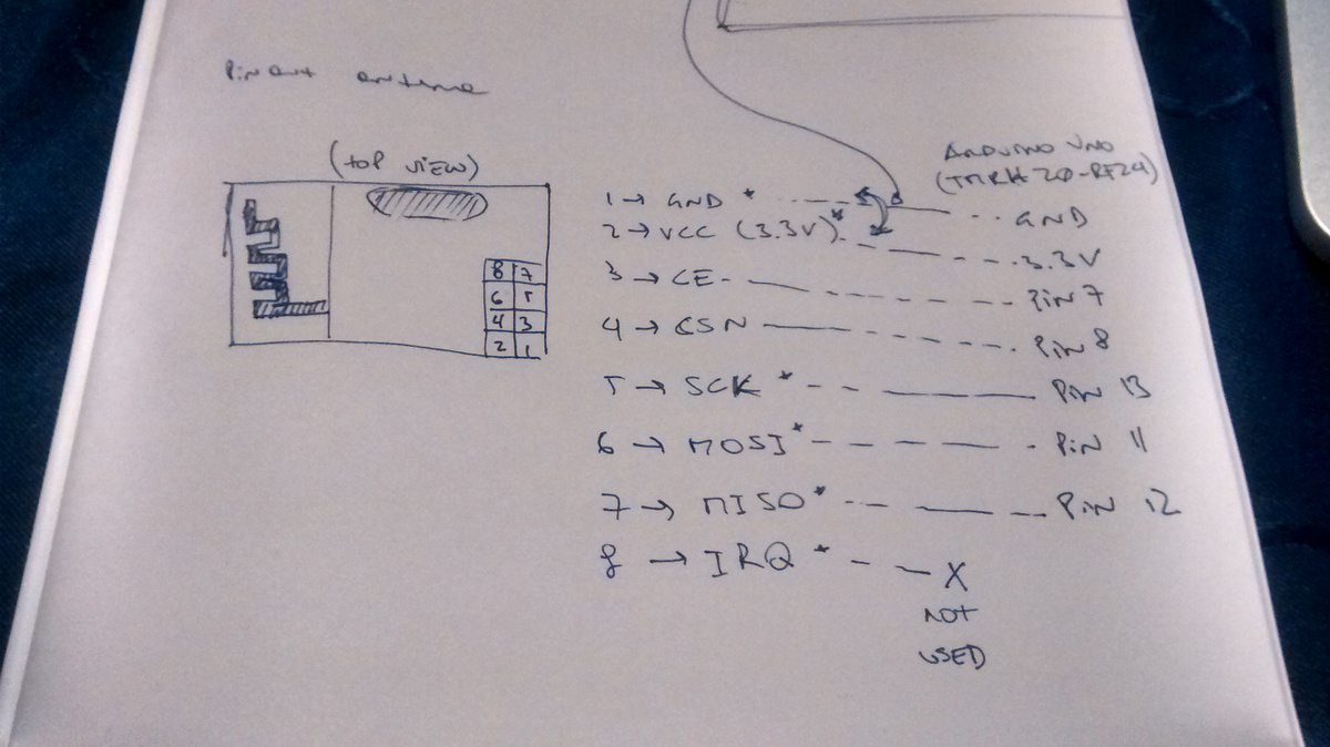
... also by looking for "arduino rf24l01" on Google would give the same result (in a tenth of the time).
Please note that the RF24l01 modules show the same problem that I faced when trying to program the AVR microcontrollers, that it's easy that the power supply can't absorb some consumption peaks, resulting on the device to turn off during work. To solve this, this site suggests connecting a 0.1uF and a 10uF capacitor in parallel between the GND and VCC (3.3V) as shown here:


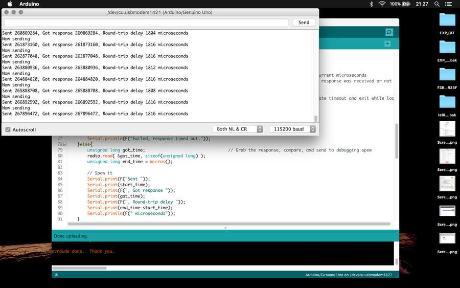
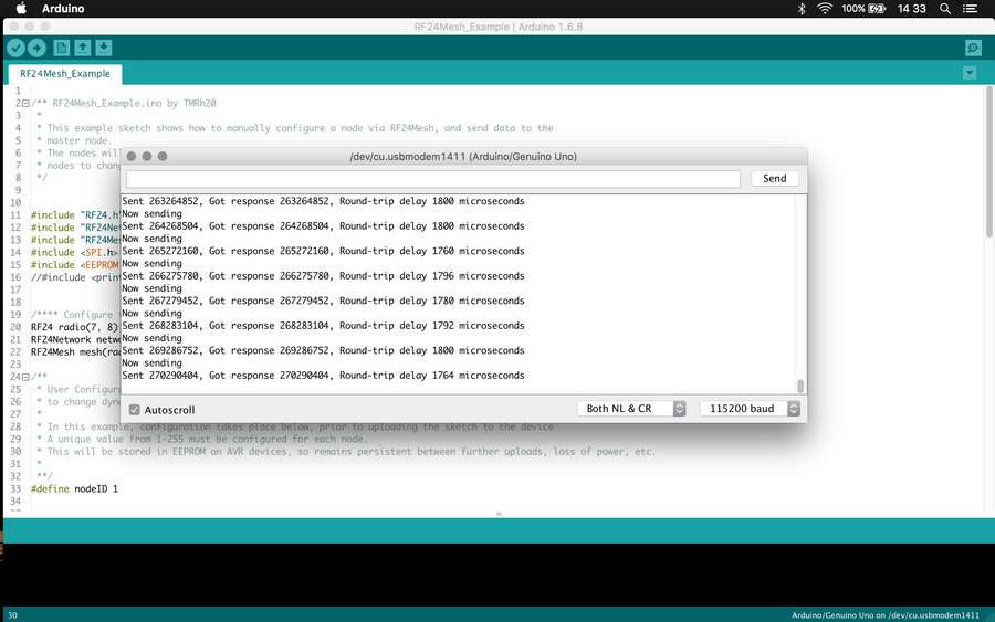
So, after loading the File > Examples > RF24 >
GettingStarted into a couple of Arduinos (changing the
radioNumber id number to each) I got the antennas to communicate
both boards.
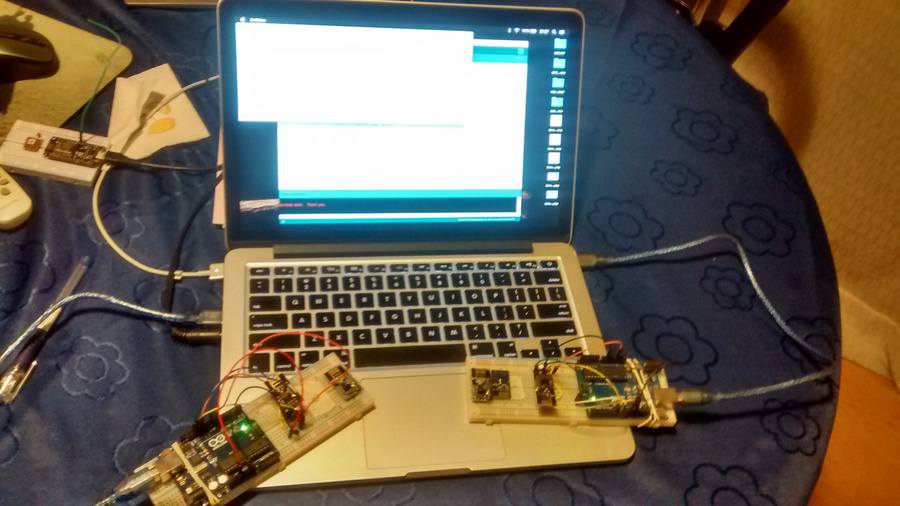
And here is the network communicating with the modules attached to different computers (to see both serial monitor outputs)
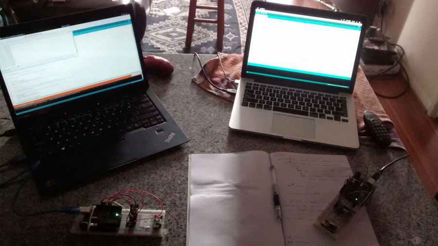
This can be considered as the first baby step.