Assignment 11
Output devices
Add an output device to a microcontroller board you've designed and programme it to do something
Learning outcomes:
- Demonstrate workflows used in circuit board design and fabrication
- Implement and interpret programming protocols
Have you:
- [ ] Described your design and fabrication process using words/images/screenshots
- [ ] Explained the programming process/es you used and how the microcontroller datasheet helped you
- [ ] Outlined problems and how you fixed them
- [ ] Included original design files and code
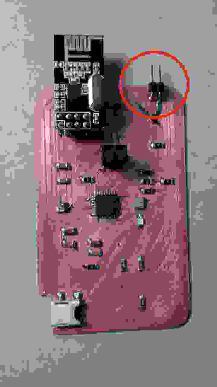
My final project consists on a lamp set that network among them through a nRF24l01 module, and the actual operation of the lamp is done with a couple of capacitive touchpad buttons; one is for operating the lamp light's intensity and the second is to control the further lamp (as when the bed is too cold to move and turn on|off a lamp).
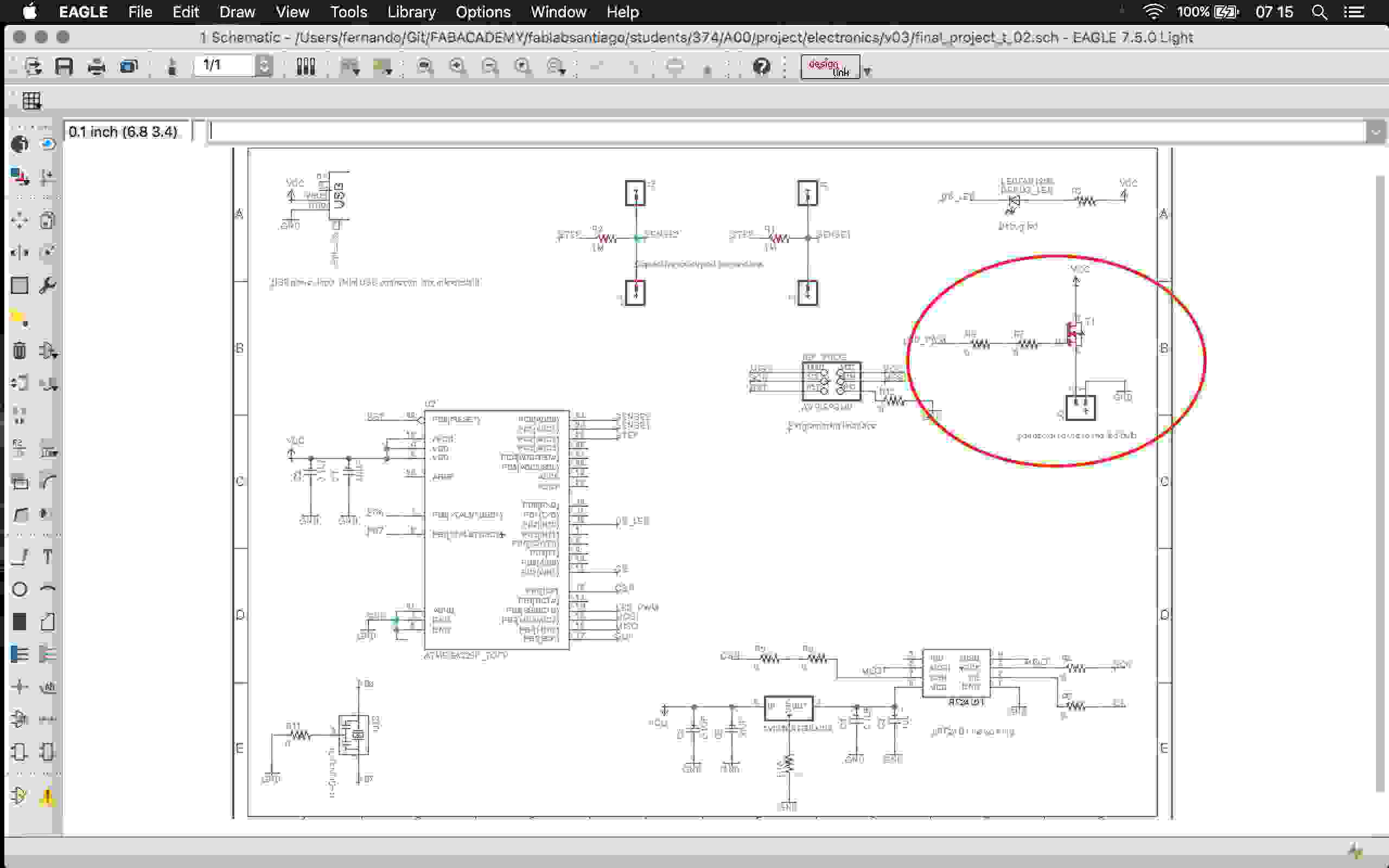
So my output devices homework will be the test and implementation of the light's intensity control, which is basically a PWM pin over a MOSFET that controls the light intensity. This is necessary since I have many high power leds connected and it would be damaging to the micro-controller to feed (or try to feed) the amount of current this LEDs need.
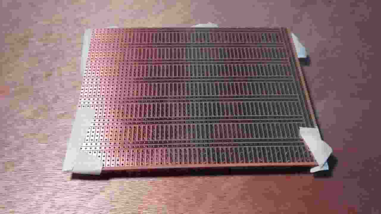
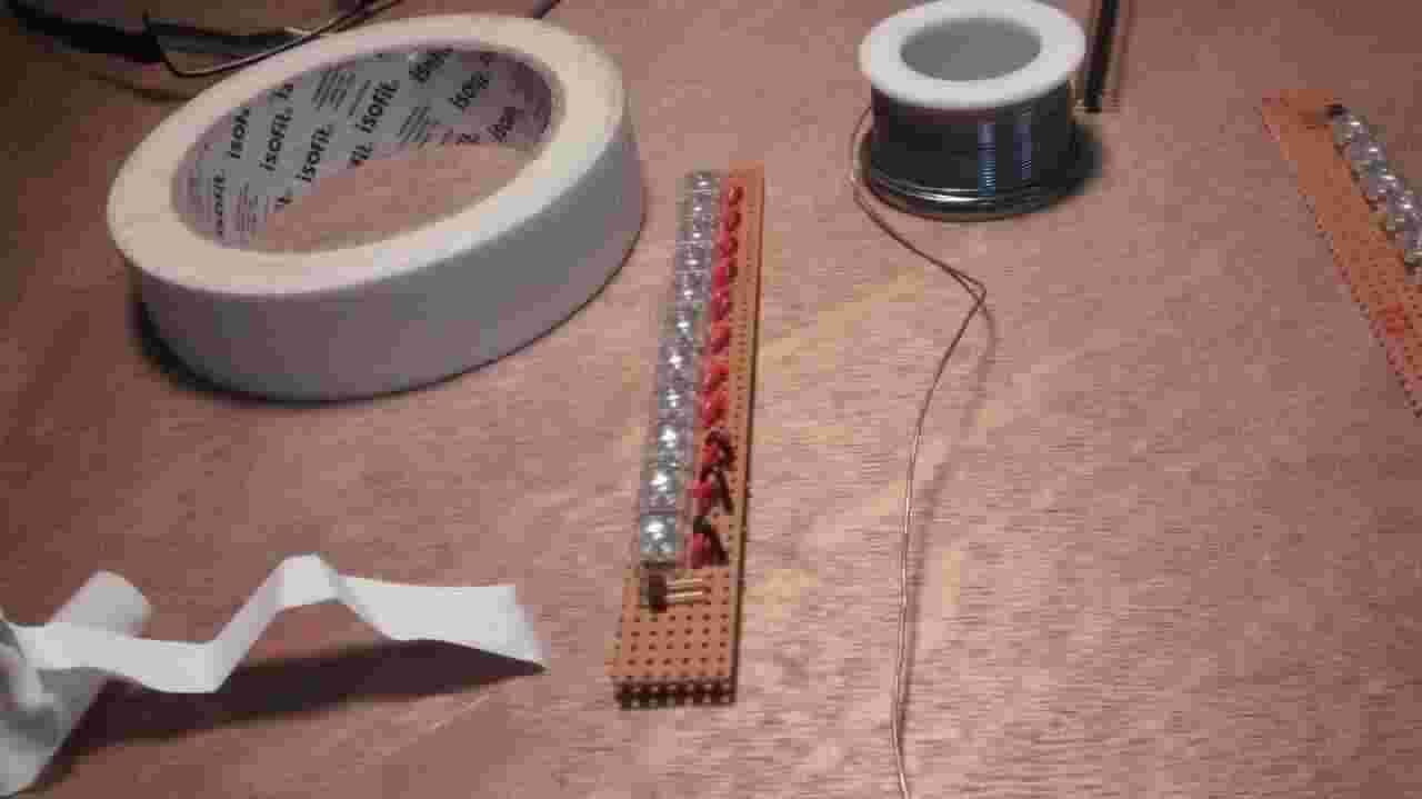
My goal to this assignment is to test and implement the illuminating system; as can be seen on the final project's 2nd iteration I just left the connector to the lamp until I could dimension the load.
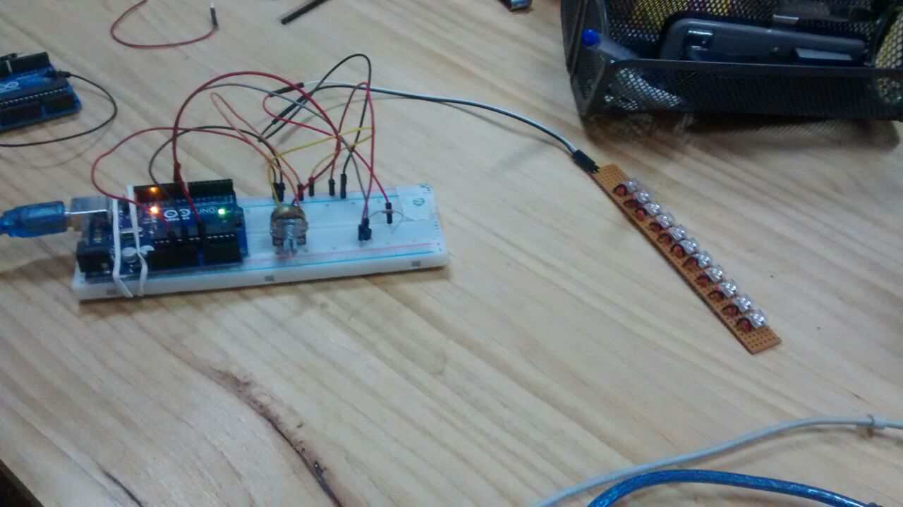
So I proceeded to reproduce this simple Arduino sketch to play with the PWM to control the light intensity that helped me to define the resistor value to be attached with the LED arrangement of my final project (I ended up using this site to do this).
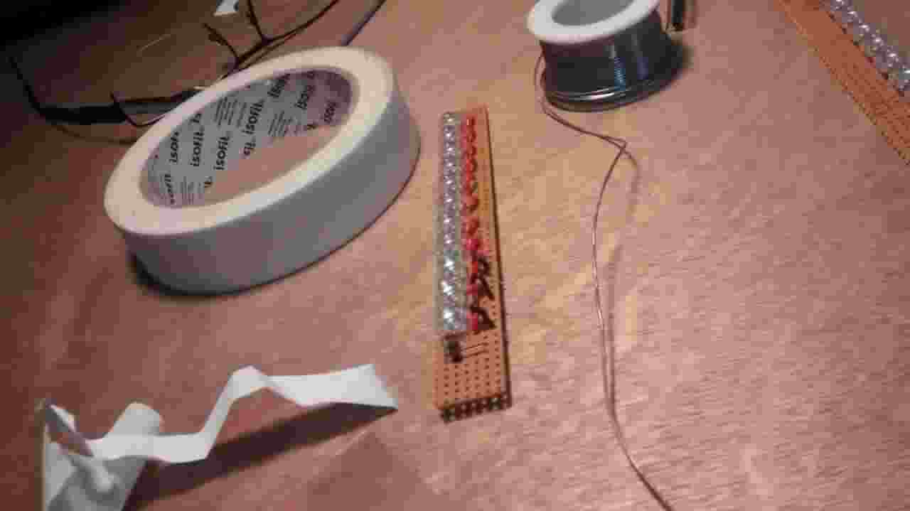
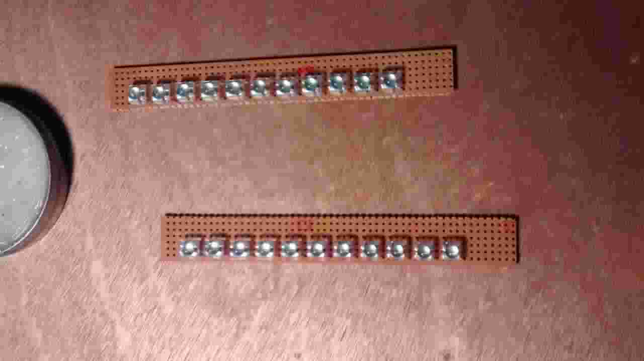
So a 10 Ohm resistor has to be attached to the LED panel ... the final control will be properly coded on C on the final project .
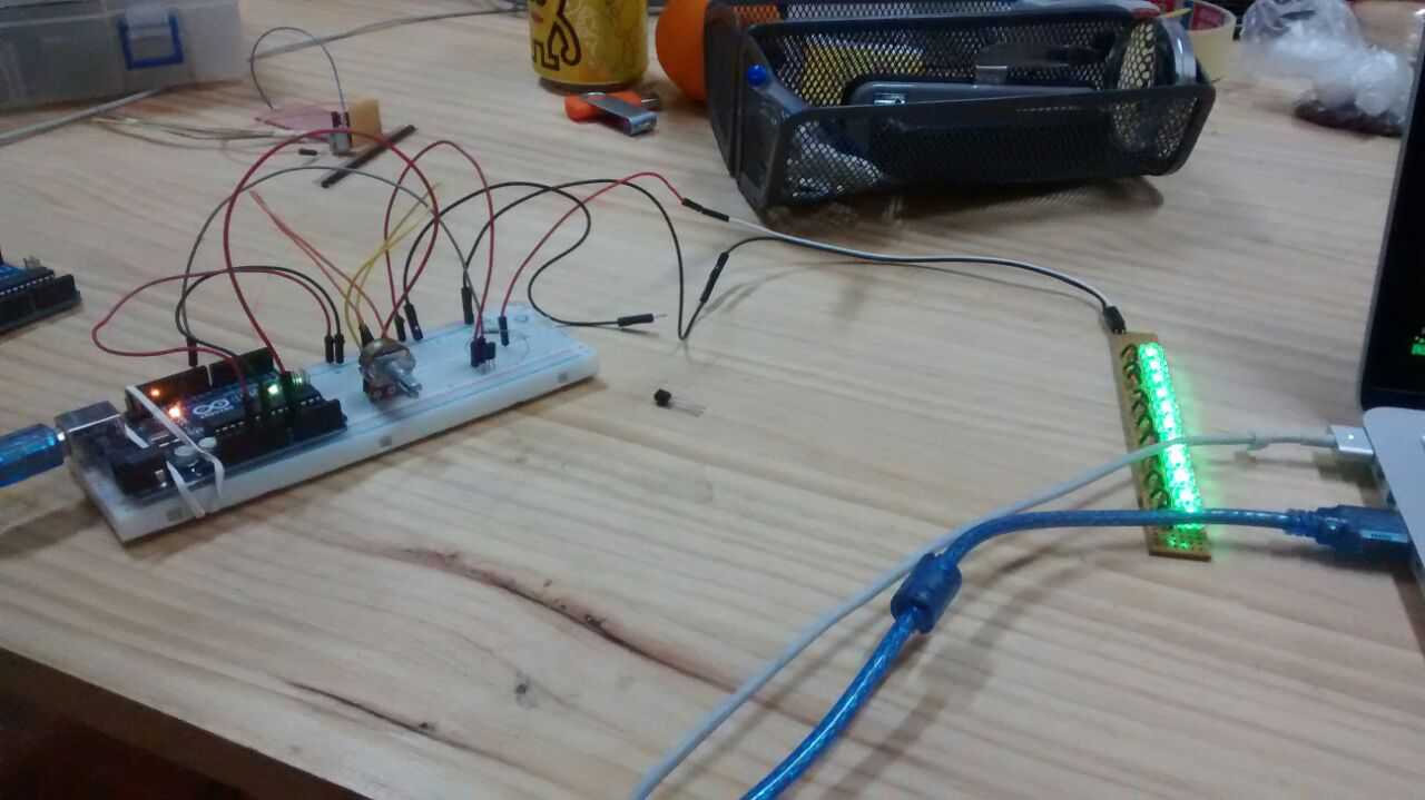
PS: I forgot to mention that I'm aware of the Arduino board limited power source, so I also succesfully run the test plugin the panel to an external power source, similar to the one that's going to be used on the final project