Week 8
Embedded Programming
The assignment for this week had the following parts;
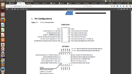
- • Read microcontroller datasheet(s)
- ATtiny44
- • Program the board to do something, with as many different programming languages and programming environments as possible.
Fabisp Board
Arduino Beginners
My Board
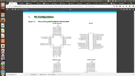
I read through most parts of ATtiny44 datasheet and learnt alot however, I had to read one more datasheet i.e. for Atmega328. This was informed by the fact that could not be found locally from the stores. With this regard, I had to redraw my board replaceing the attiny44.I learnt about;
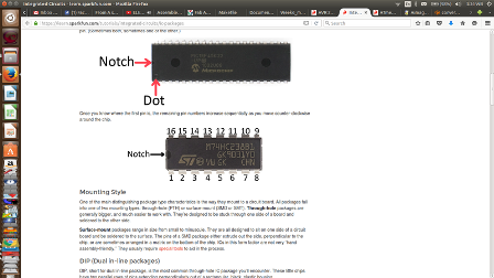
I tried to understand further the pinouts ie pins and codes. With the available information I could now see clearly see where to connect the Microcontroller pins. From my schematics and even the board, I was able to identify the pins.
-
Downloading the software
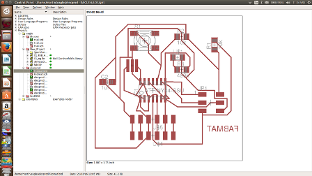
I realized that I had several errors in my previosly designed board and so I opted to redesign it inorder to get the correctly working board for programming. Alos I had to replace the Microcontroller so, I had to go through the processes all afresh. Now that my board is available and I then started to download the necessary files in order to start programming it.
My board
Simple steps
- The main software to be downloaded is the Arduino IDE- it is a free and open source software
- Install the FTDI Drivers if your computer have used FTDI cables before, we have to install the drivers in order to be recognised by your computer. We can check the avalability of drivers depending on our operating system
I also had to get more tutorials AVR SetupTutorial
Note:The board should be programmed with the programmer done in the assignment of ELECTRONICS PRODUCTION and the board to program will be the one done in the ELECTRONICS DESIGN assignment.
Being a beginner and very new in Electronics and generally programming, I was adviced to start simply by running the Arduino software, as it has been designed to be used by normal people and not just programmers alone.
More reading
Atmega328Foundations of Programming: Fundamentals by Simon Allardice
Up and Running with Arduino by Peggy Fisher
Arduino Pulse Width Modulation by Rae Hoyt
Secrets of Arduino
C Essential Training by Isac Artzi
Arduino tutorial from student
Burning Bootloader
Arduino Tricks and Techniques
Microcontrollers Tutorial beginners
Fab Academy 2015 Tutorials Embedded Prog
Microcontroller Pins Identification and usage
Arduino more Tutorial
After doing all these, Luise advised me that ATTiny44 could only be replaced with ATTiny45 but not with any other microcontroller like Atmega 328. This means that I had to wait much longer for the shipment of the component. Meanwhile, I went ahead to figure out how I will programme once it is availed among other
Set up
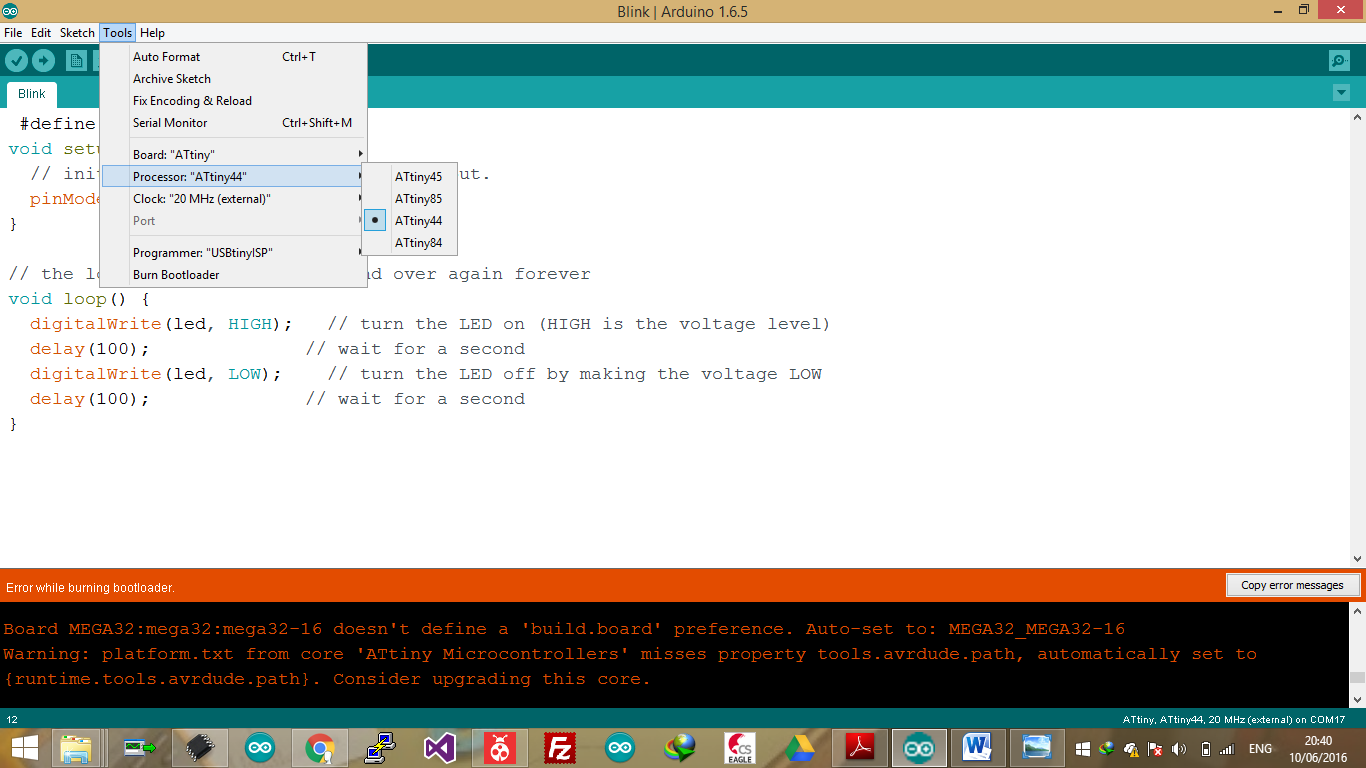
The first step before mounting the program to our Board, is actually to set all the devices to be controlled by our computer.
- We need to setup the environment to Tools menu and select Board.
- Then select the type of Arduino you want to program, eg Leonardo, Edison, Uno etc. For my case it’s the Arduino Uno.
- Then for Coding, In Arduino, the codes written are known as Sketches
- Every sketch needs two void type functions, setup() and loop(). A void type function does not return any value.
- The setup() method is ran once at the just after the Arduino is powered up and the loop() method is ran continuously afterwards. The setup() is where you want to do any initialisation steps, and in loop() you want to run the code you want to run over and over again.
- - Now connect the FabISP to the computer using the USB cable - provide power as well
- - The FabISP then connects to the Hello World FTDI board by the ISP header common to both boards and a six wire ribbon cable.
- - The FTDI header of the Hello World should be providing power to the Microcontroller
- - The VCC in the circuit (Power) which is coonected using a red ribbon cable should be well connected through the heads on both boards.
Programming process
- - Now open the already Installed Arduino IDE which automatically opens a sketch, Save it
- - Locate the Arduino sketchbook forlder. Then create a New folder and name it 'Hardware'
My Scripting Objective
I want to programme this board to be able switch on, make the blinks, and to switch off my LED It will be expected to operate as below;
- Press one time the button: LED slow blink
- Press second time the button: LED fast blink
- Press third time the button: turn on LED
- Press fouth time the button: turn off LED
Programming
ARV Dude Setup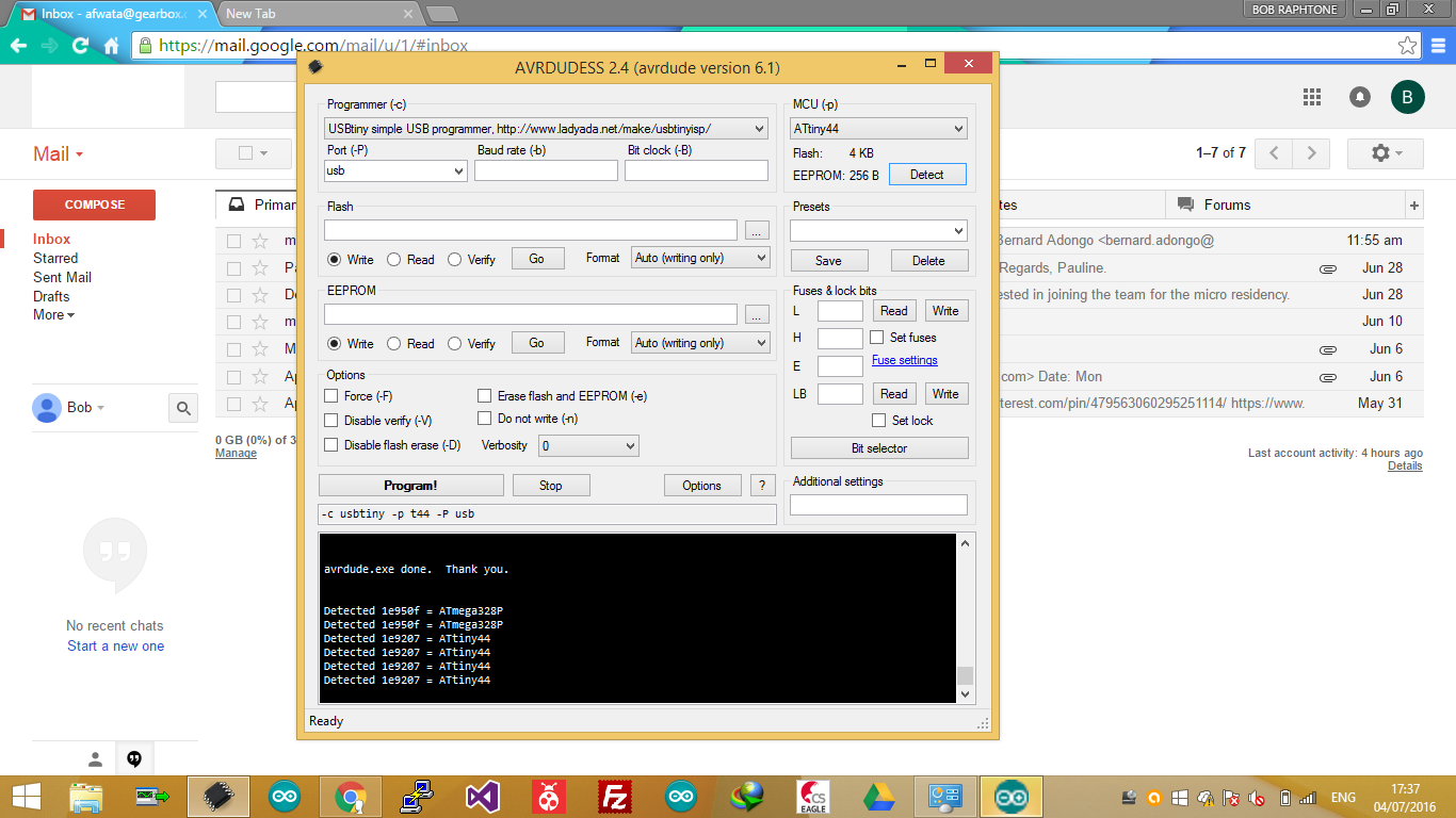
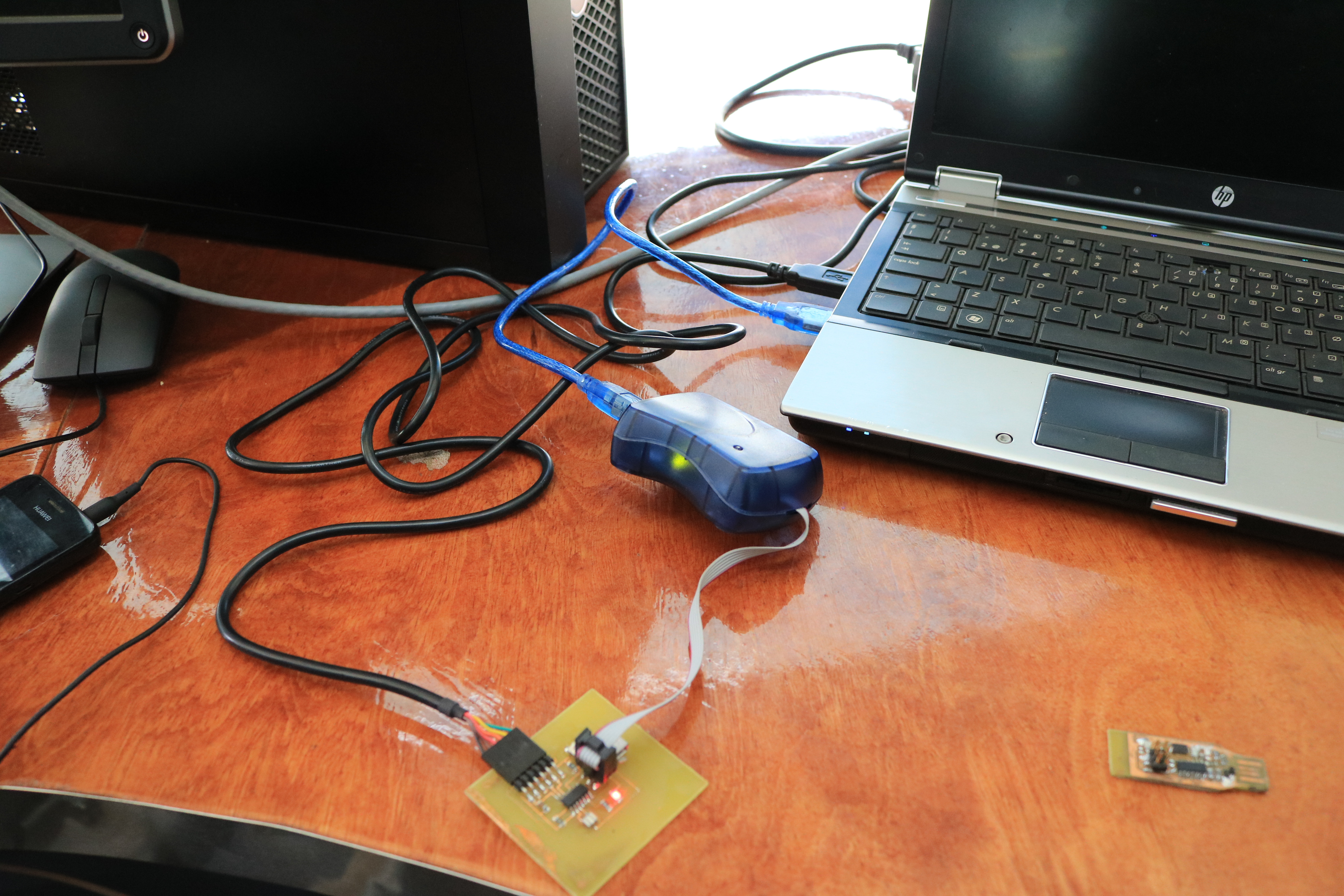
I did this board much earlier than the FABISP and so I could not use it to program this board. I again used Usb Tiny Programmer
In connecting this board to the programmer which then provided it with power. Using FTDI cable, I connected it to the computer. You could hear a sound from computer for detecting a new device.
I ran the program first to flush it then to load program
Tutorial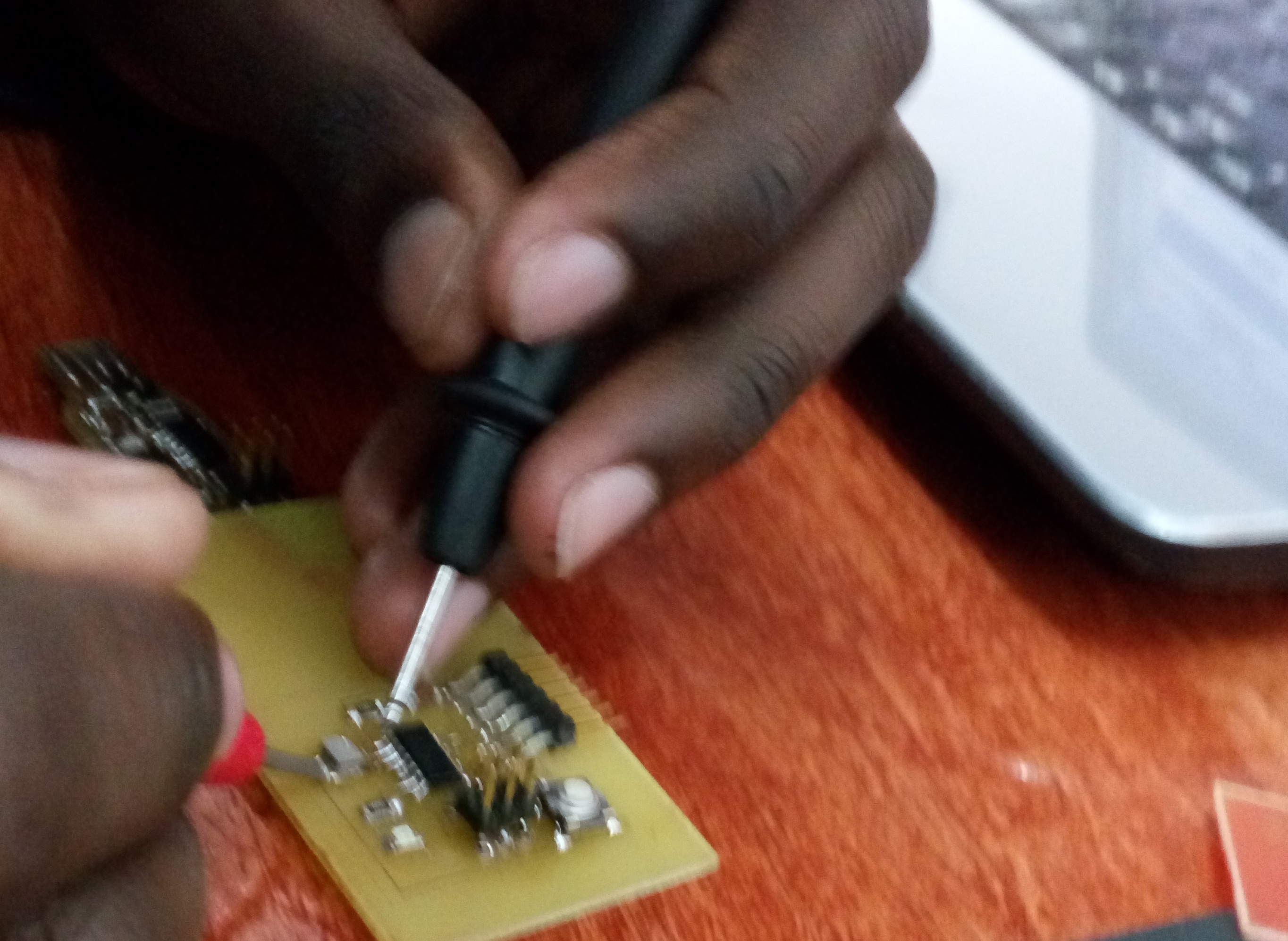
connections

const int buttonPin = 2;
const int ledPin =  13;

int counter=0;
int buttonState = 0;

void setup()
{
  pinMode(ledPin,OUTPUT);
  pinMode(buttonPin,INPUT);
}

void loop()
{
 buttonState = digitalRead(buttonPin);

if (buttonState == HIGH)

    {
     counter=counter++;
   switch (counter)
   {
     case 0:
     digitalWrite(ledPin, HIGH);
     break;
     case 1:
     analogWrite(ledPin, 150);
     break;
     case 2:
     analogWrite(ledPin, 255);
     break;
     case 3:
     digitalWrite(ledPin, LOW);
     break;


     }
   }

}