Week 3

Assembly

Computer-Controlled Cutting

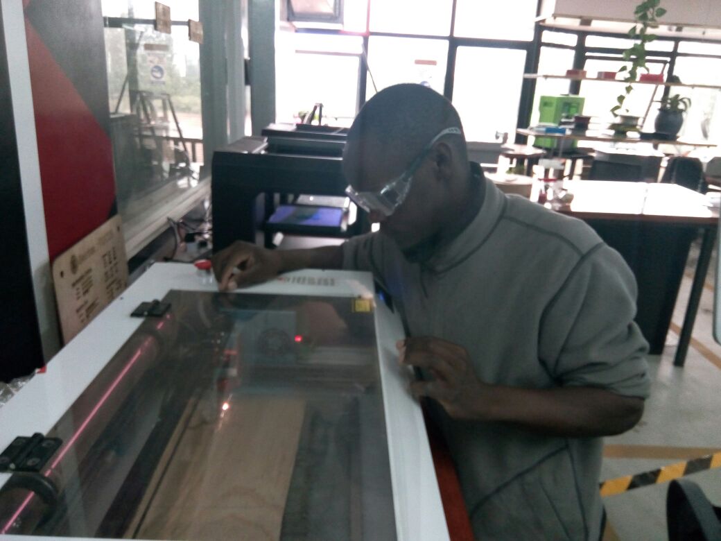
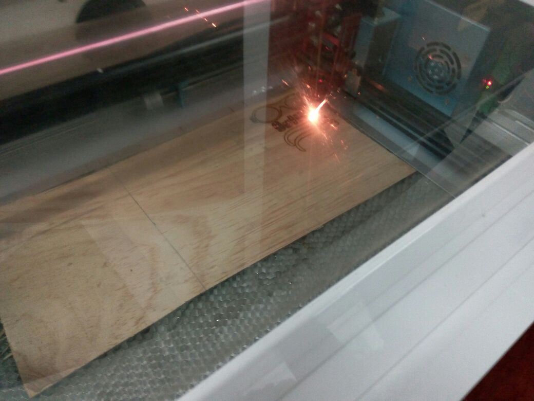
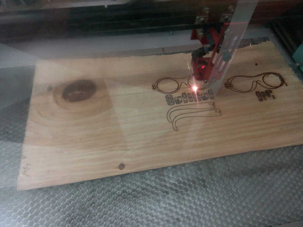
This has been another interesting week for me. I learnt a lot .I learnt the two major machines here; laser cutter and the vinyl cutter. I learnt the general operations of thes machines and their various parts.Laser cutter is able to handle various compuer designed cuttings of differnt materials depending on the machine capacity. It can be so good for commercial productions since a single design can be reprinted as many as you need.For this class, this is the ideal machine for the assignment for the week.

The vynyl cutter is also another important machine in Fablab, it does cuttings for smaller circuits and screen printing stencils. The works faster with vynil and other materials of smaller thickness

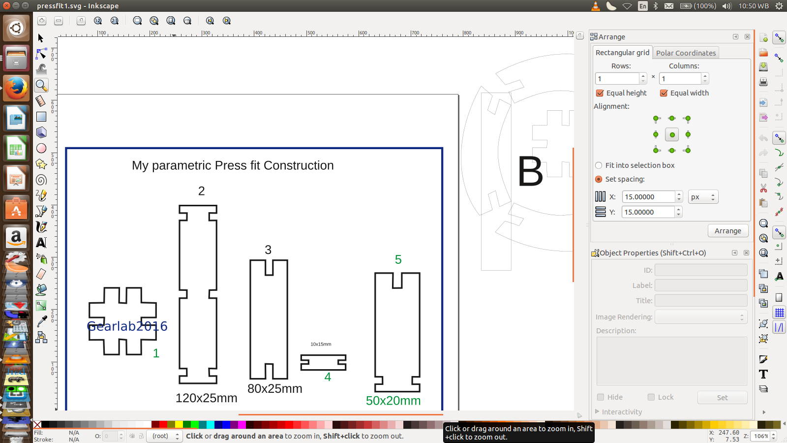
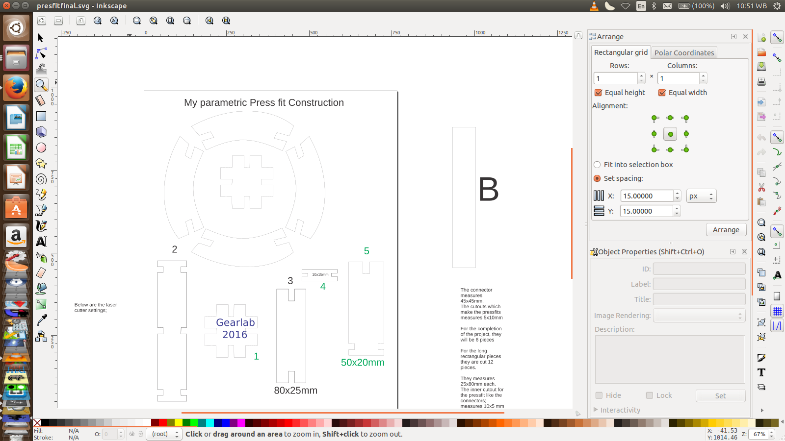
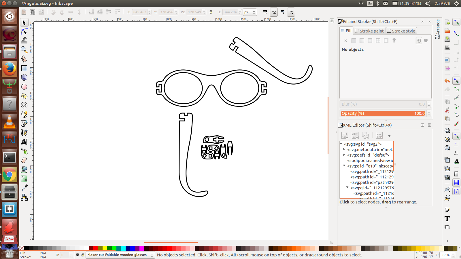
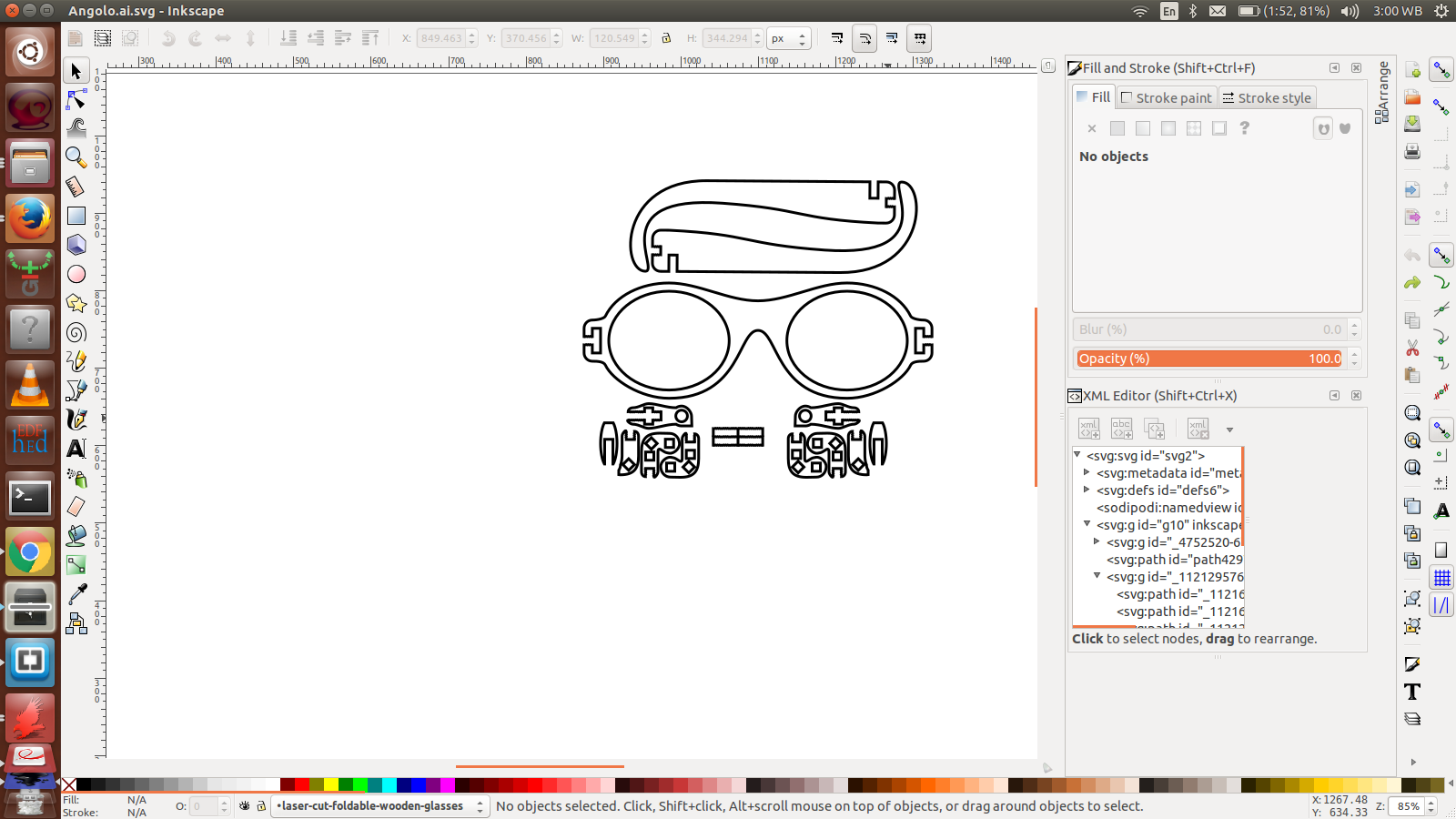
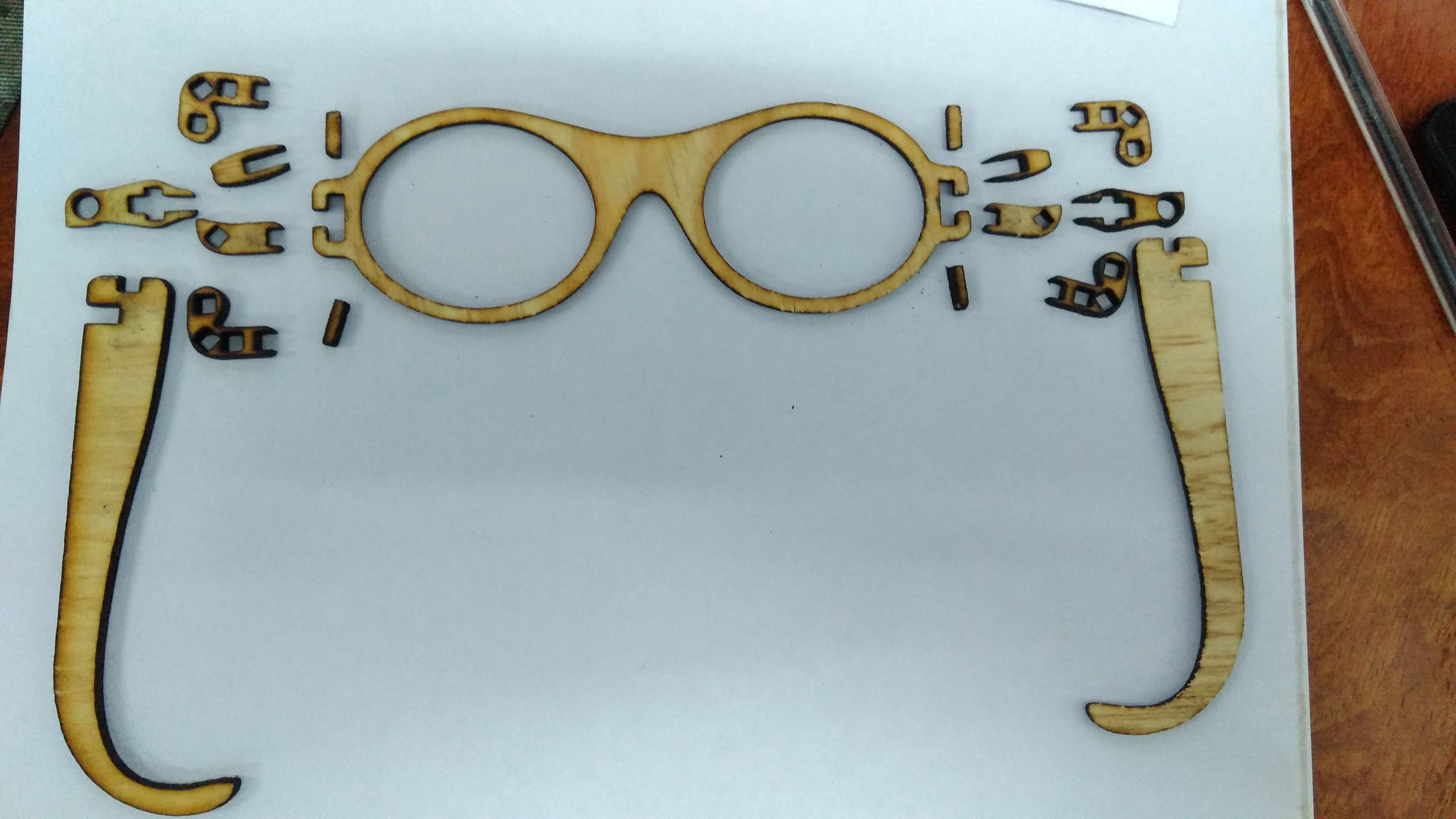
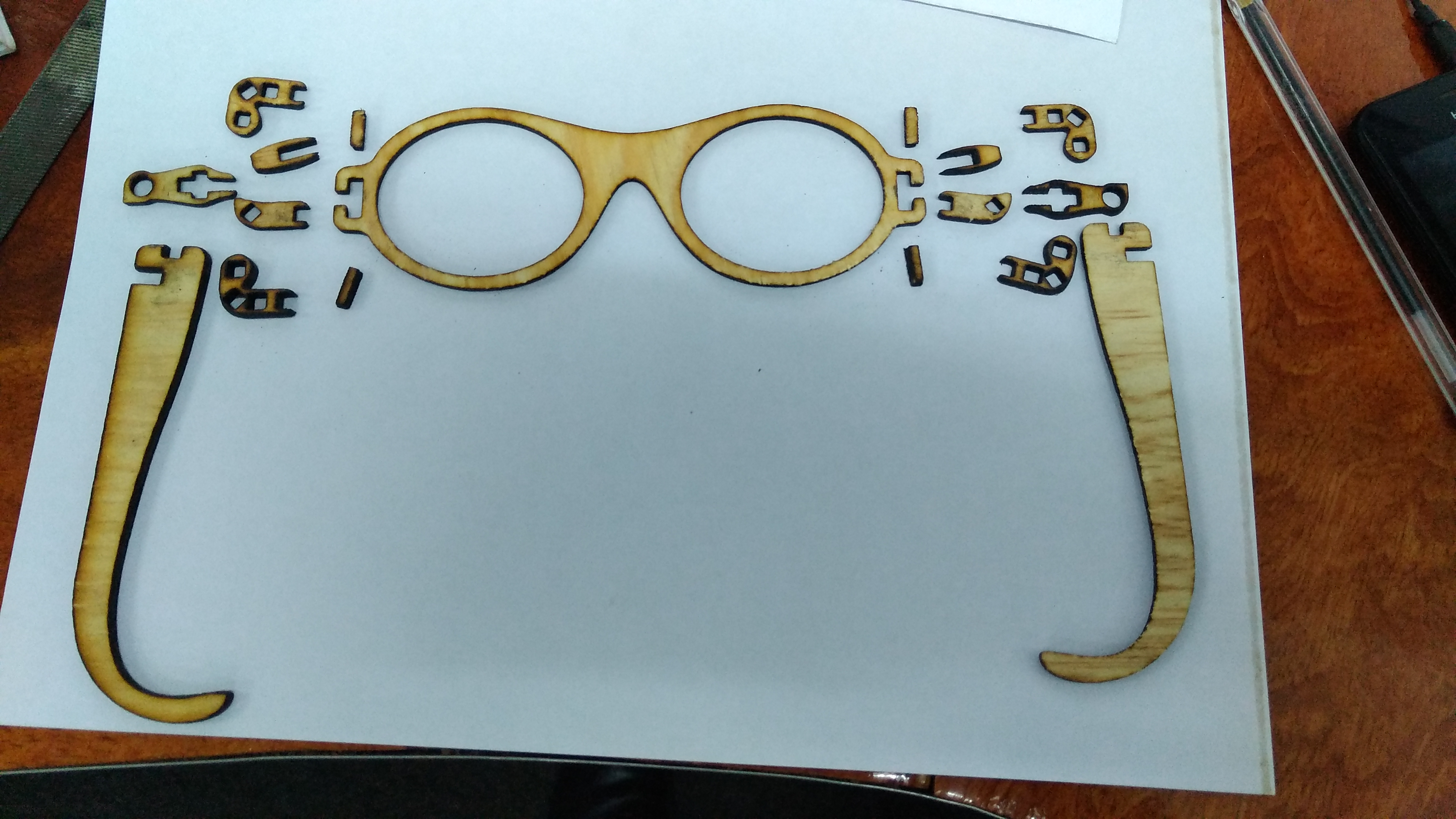
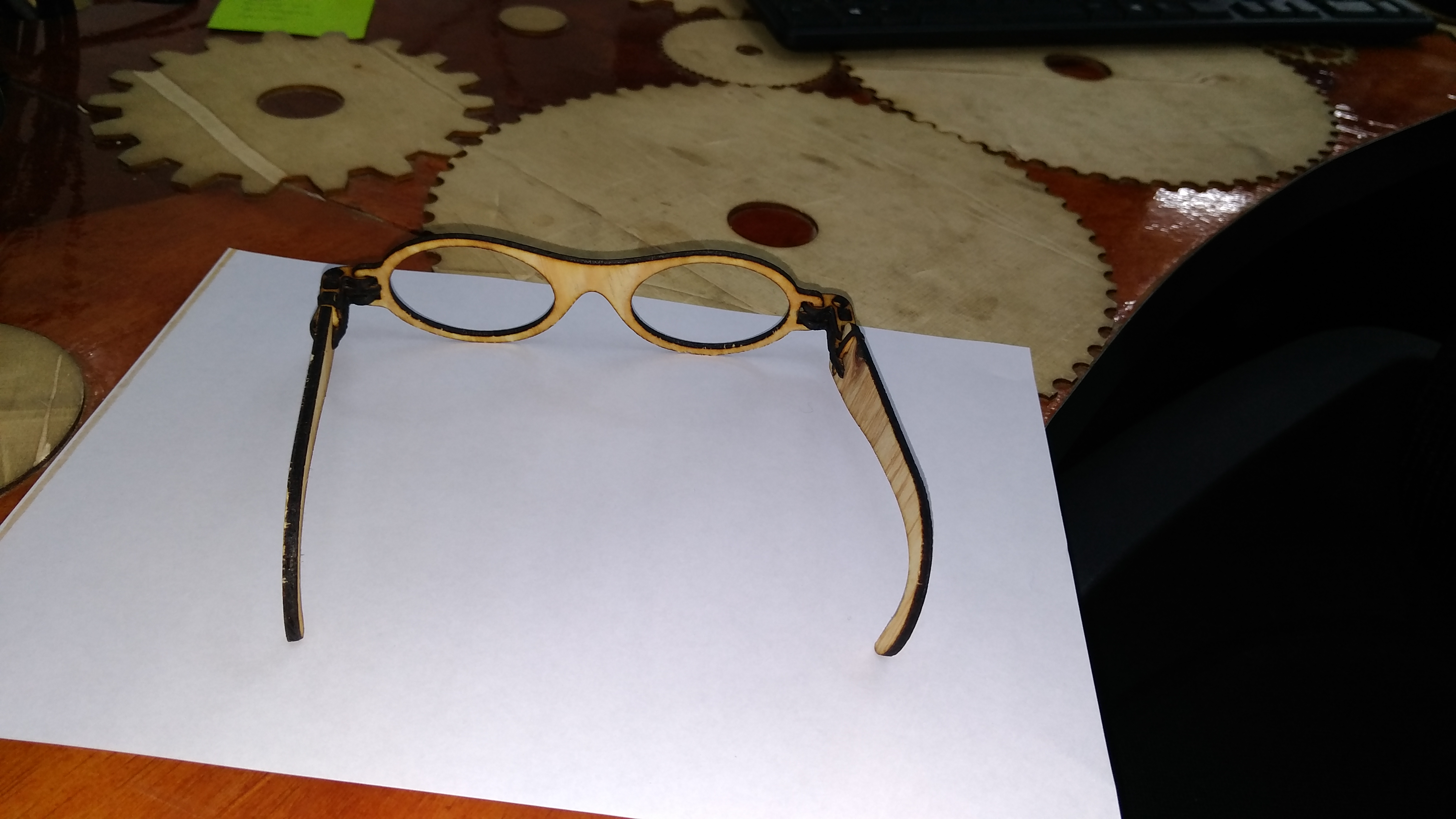
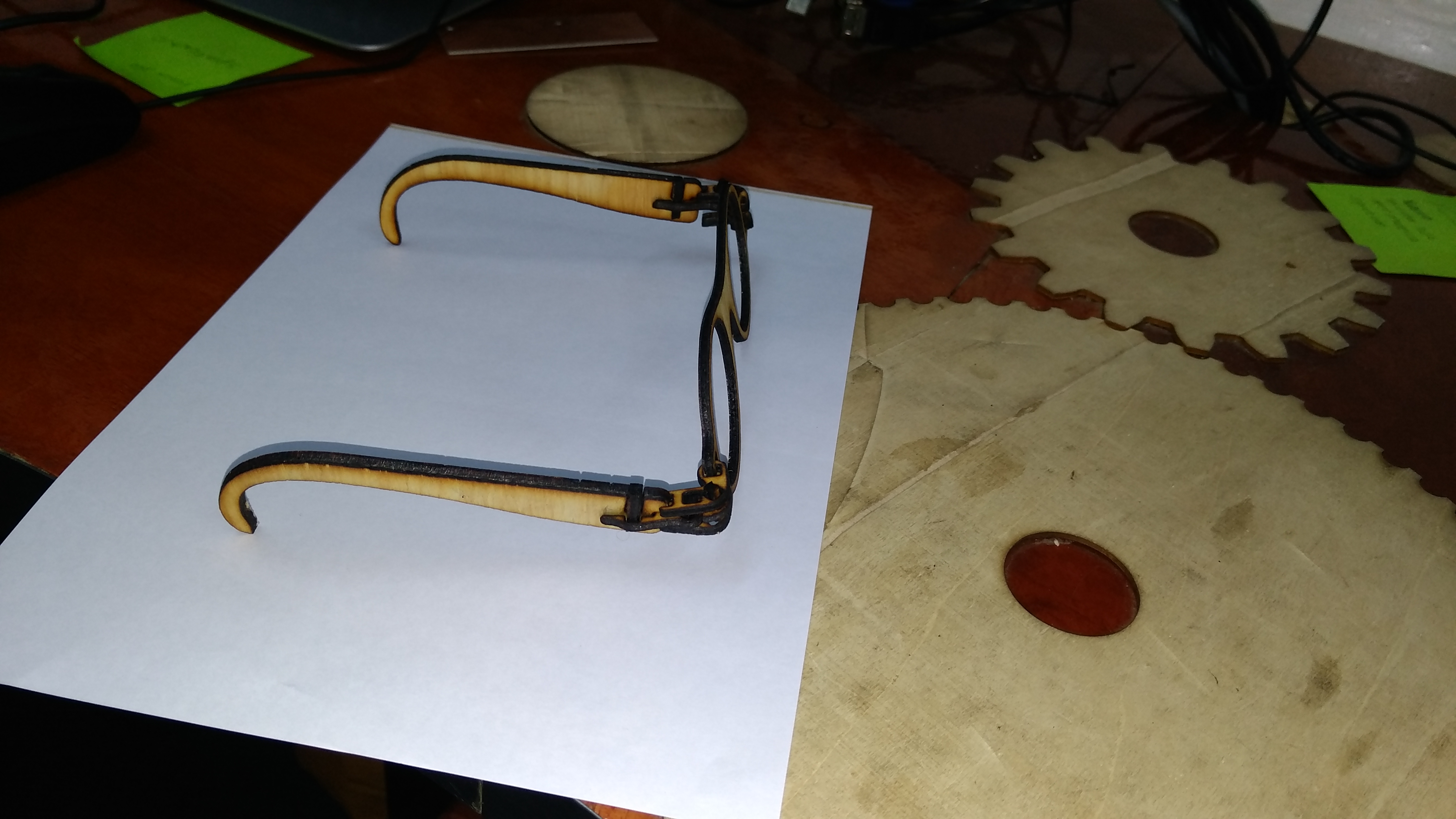
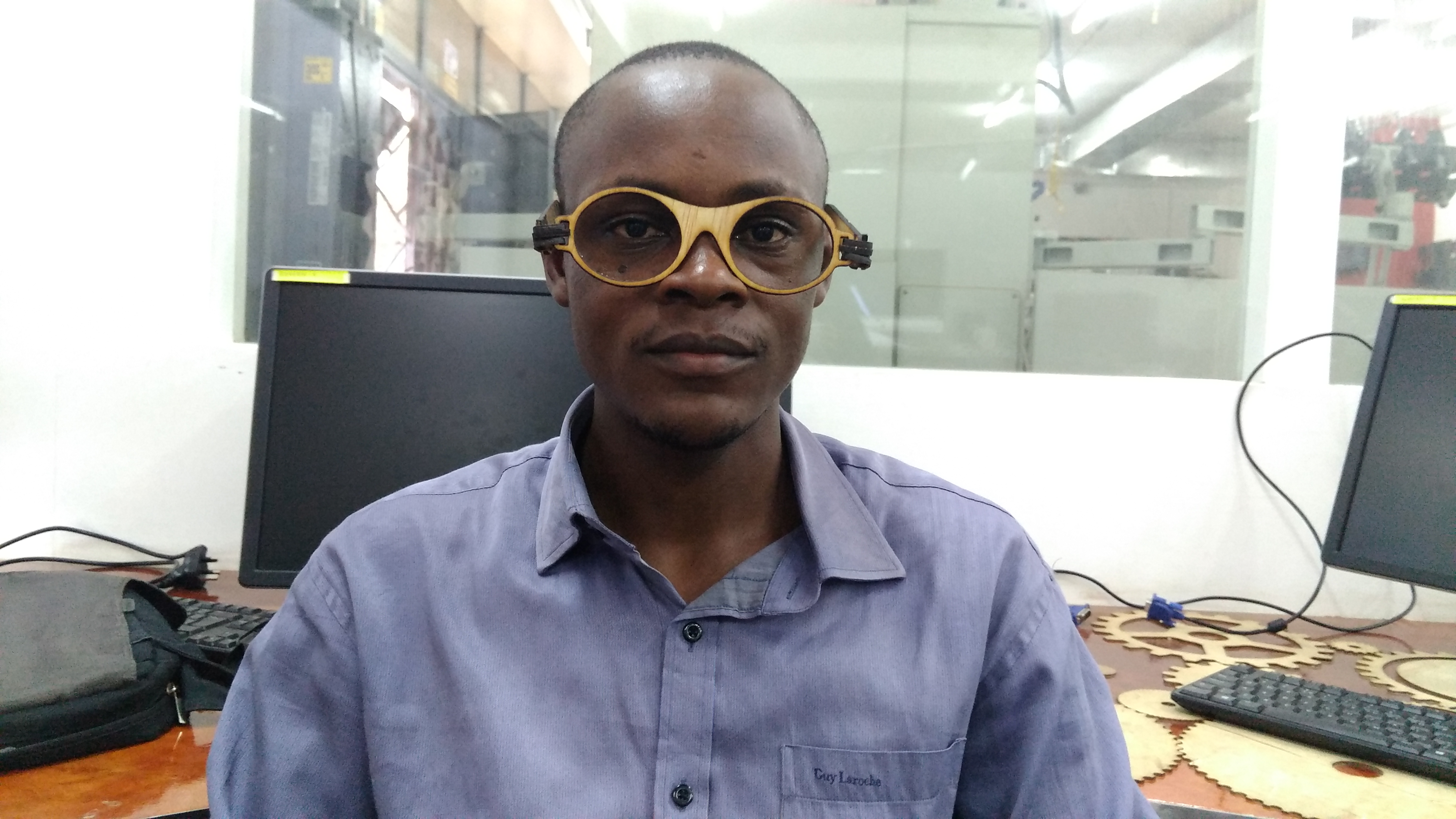
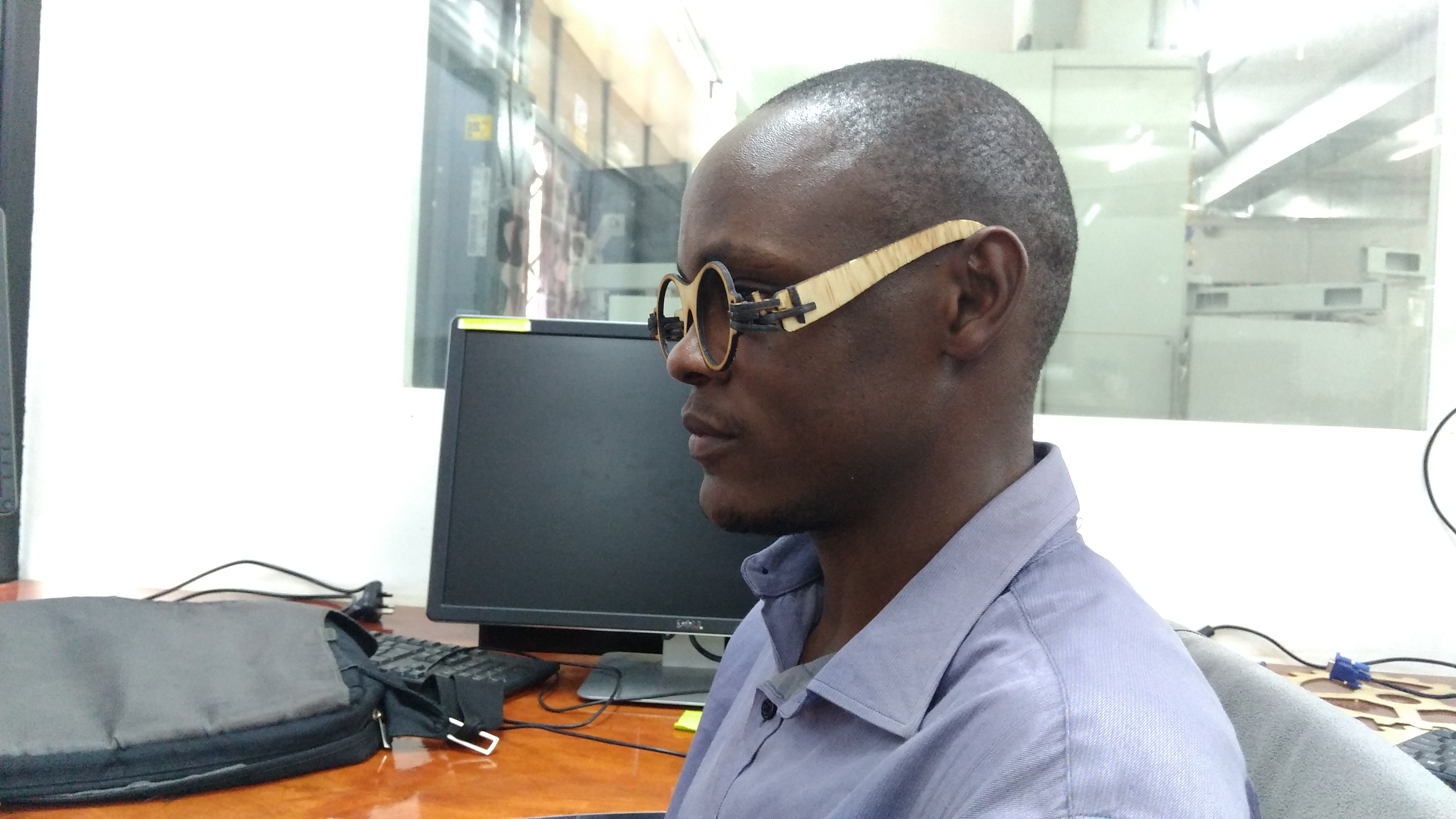
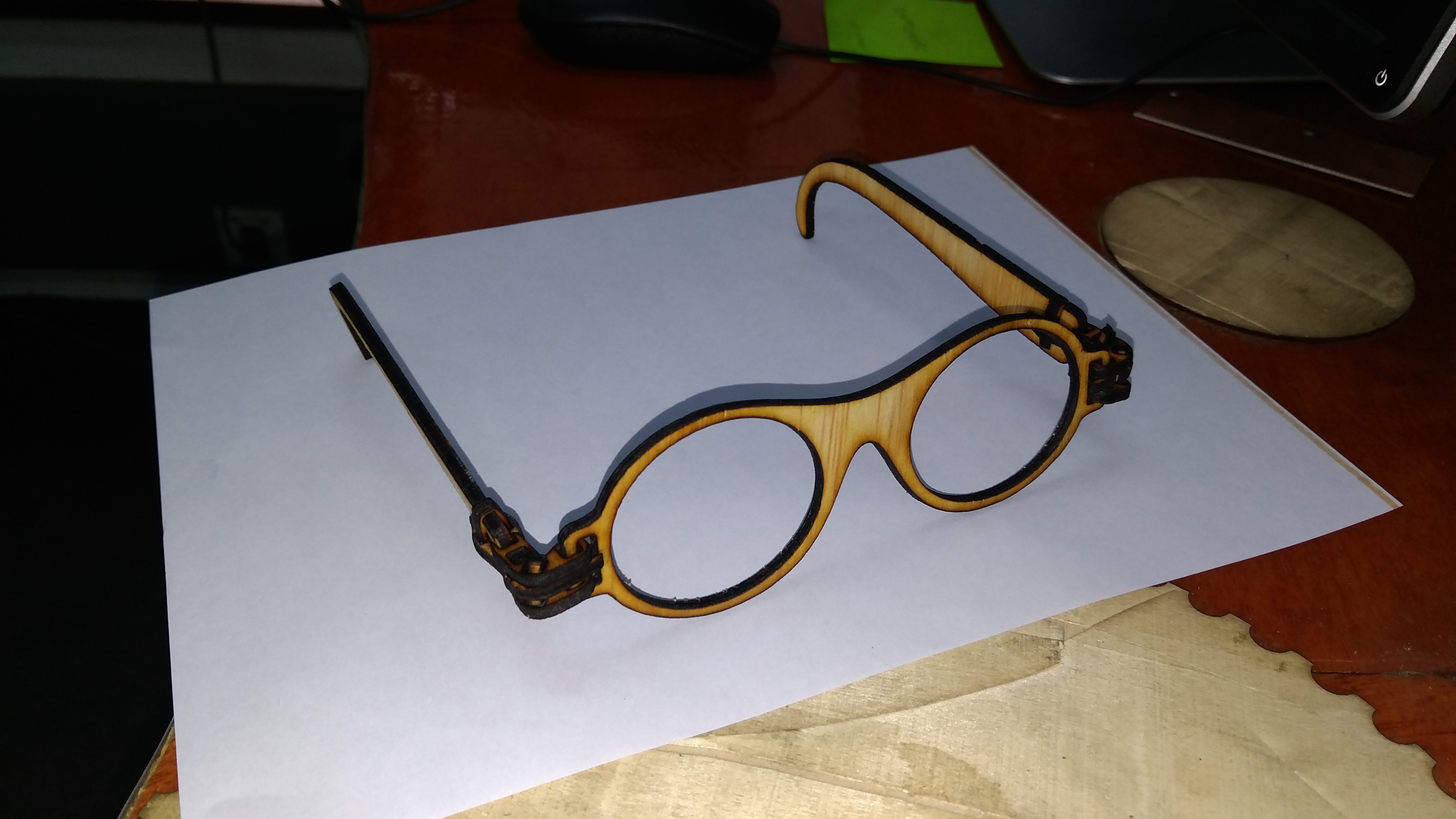
The week's Assignment therefore is do Computer Controlled Cutting for a Parametric Press-fit Construction Kit. After viewing other parametric press fits for former students' files Students Achive and other sites like for Epilog laser and Instructables, I came up with my design as below;


Plans

    - Machine used: laser cutter
    - Material used: Acrylic material with thickness of 6mm
Diagram
The Parametric press - fit Constructions Drawings
Diagram

This was done with Inkscape. Here, tools like like path nodes editor and Bezier for curves and straight lines was so helpful. Also used the Measurement tool, rectangle & square tools. The drawing wasnt good enough following the challenge with the tool for editing nodes on paths.
Even-though it provides an opportunity for the 3D image viewing, I still went ahead to try other software and this landed me to CorelDraw. This is a superb tool for the 2D designing like for the one I was doing.


Diagram

Diagram

Project description

The Pressfit I made is globe-shaped in completion (see the image below). It has five (5) different shapes and sizes cutouts. These small pieces are able to fit into each other fit enough.

Below are the measurements of the pieces;

    1.The connector measures 45x45mm. They are square with a notch on each side measuring 10x5mm
    2. The cutouts which make the pressfits measures 120x20mm. These will be 4 in number and will be joining the 'North and South poles'
    3. For the outer curves; they are rectangular 8 pieces measuring 80x30mm.
    4. Inner connectors; these are 4 small pieces measuring 30x10mm. They connect the 'North/South' pole pieces to the horizontal piece
    5. Middle connectors, they are also 4 pieces connecting the curves to the centre pieces. They have notches on both length sides closser to the end measuring 5x5mm each and one measuring 5x10mm on the other width side away from the previous ones. this side connects to the centre. They measures 20x80mm each.

Diagram
And the complete top
Diagram


Lessons learnt
I managed to manouver through the corel draw so comfortably. I perfected myself in usage of measurements. I can now handle most tools of corelDraw. I realised that I need more practice with other relevant programs and especially Inkscape which I have been regarding to be so easy to manipulate. In my initial stages of imaginating what to design, I hade to use small hard papers to cut them physically using a pair of scisors at home just to make sure that my imagination can be actualized and done practically. I guess that if I continue practicing the 3D programs, I will better do it next time but it was a great experience.

All in all, I finally decided to do a real project Angolo Specs. These are simplistic wooden spectacles ( Am avoiding using the name "Glasses" since all parts are made of wood. It provides a chance to customize your own specs to your taste and preference; laser cutting and pressfitting the parts.

Background

Many people like using specs from time to time either for madical reasons, safety, beauty or any other reasons.This is enough reason why anybody would like to make one for themselves

Angolo Pic
Angolo Pic

Designing

The designing was done in inkscape individually. It has several small parts epeciallyfor 'hinges' that joins the face and the arms.The other parts are large enough. A total of 5 parts were designed but 4 of them are duplicated since they are common to both sides of the spectacles.

Angolo Scrn
Angolo Scrn
Angolo Scrn

Arrangement for laser Cutting

I had to arrange all the designs in a well systematic manner to ensure that I can maximise usage of the small piece of the material I had.

Angolo Scrn
Angolo Scrn

Laser Cutting

When all my files were now ready, using Full Spectrum Laser cutter, I cut all the pieces from a piece of plywood. The Settings for cutting were set at 5 passes with Power of 100 and Speed of 40. This gave a perfect cut of all parts at once.

Note: That different materials need different settings of Power, Speed and Passes.

There are two types of laser operations:
    - Engraving and
    - Cutting

1) Raster data is composed of pixels so as you zoom in, you will eventually see pixilation of the image as seen bellow. Example file types of raster data include .jpg, .gif, .png, and .bmp. During rastering the laser head will move from left to right (like a printer) from top to bottom.

2) Vector data is defined by parametric equations (even if you zoom into a line, it is not going to be pixelated). Vector data includes straight lines, circles, rectangles, and splines sketched in vector editing software such as Adobe Illustrator, Word, Inkscape, Solidworks, (DXF, SVG, PDF, etc). During vector cutting, the laser will follow the path defined by the lines.

The lines have to be drawn with a thickness below approximately 0.25 pt. Otherwise, the software will recognize the line as 2 lines instead of one.

Some of the materials recommended to be used in laser cutters include; Acrylic, Some plastics, Rubber, wood, leather, Textile/Fabrics among others

Laser Cutting Tutorial
Angolo Scrn

There is need to wear protective/ safety gears like glasses to ensure thatyou dont harm yourself during the work

Angolo Scrn

A single pass was not able to cut through the plywood so I had to increase 2 more passes. Unfortunately, the laser cutter stopped abruptly but could not establish the reason why. During this time, part of the material which the laser beam was pointing got burnt badly and so damaged the work. After a new start, I managed to cut it well

Angolo Scrn

Assembling

The parts were assembled as below;

Assembly
Assembly

When assembled well, this is the product you will have. More different designs and sizes can always be done.

Assembly
Assembly

Finished Product

Assembly
Assembly

Files

Pressfit
Angolo Inscape