For this week's Lecture was on the Input Devices; how you use a microcontroller for processing input and about various input sensors like switches, motion-, distance-, magnetic field-, temperature-, and light sensors, among others and the implications of using them. One that stood out from the rest was the step response sensor which can be utilized to measure an array of properties like resistance, capacitance, inductance, position, pressure, proximity, tilt, acceleration and humidity. Also see this weeks' class Class Tutorial file to get an overview of the subjects in addition to the lecture you watched above. The Assignment was to measure something: add a sensor to a microcontroller board Fabkit board that you have designed and read it
Week 11
Input Devices
Assignment
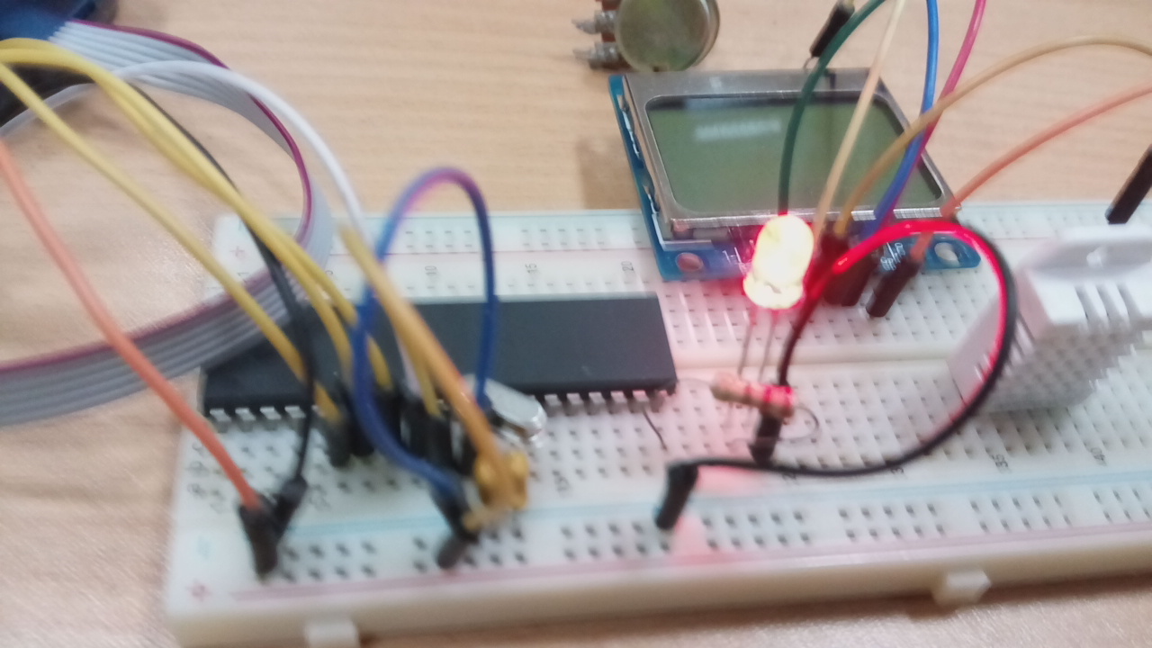
Since I had not made my Fabkit, I decided to use a breadboard and arduino to test the concepts. Below were the components used;
- • Breadboard
- • AVR programmer
- • Atmega 32 MCU
- • Light sensor
- • Button
- • DHT 22 for Temperature & Humidity
- • LCD
- • LED
- • Resistor
- • Crystal 16Mhz
- • Two 22uF Capacitors
- • Jumper wires
Softwares
The Softwares used here included;
- • Arduino (1.5.4
- • Atmel Studio or
- • AVR Dudess
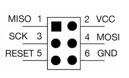
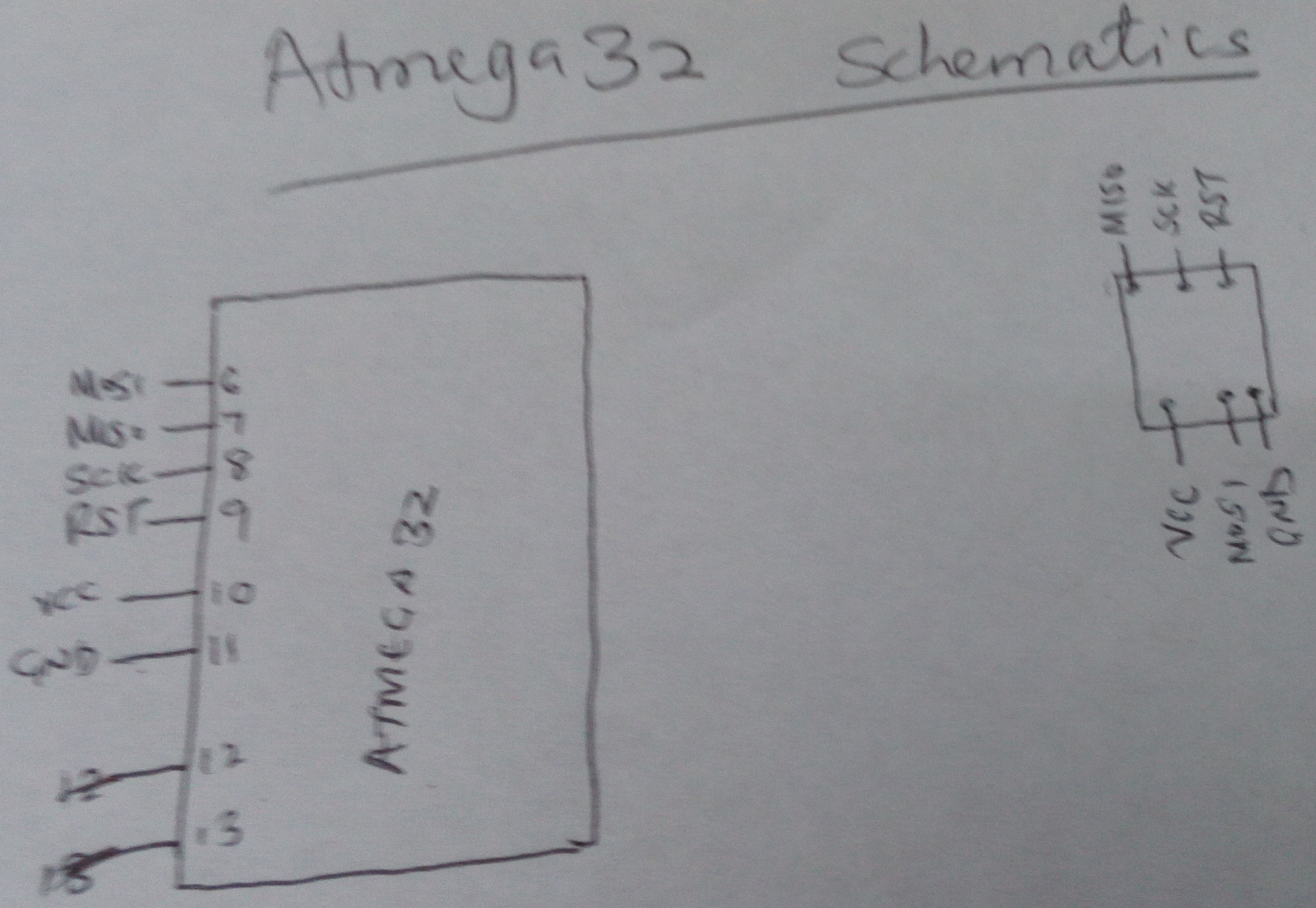
Detecting ATmega32
Connect ATmega 32 microcontroller to the USB programmer as shown below;
Process
- • Open AVRdude/ Atmel Studio
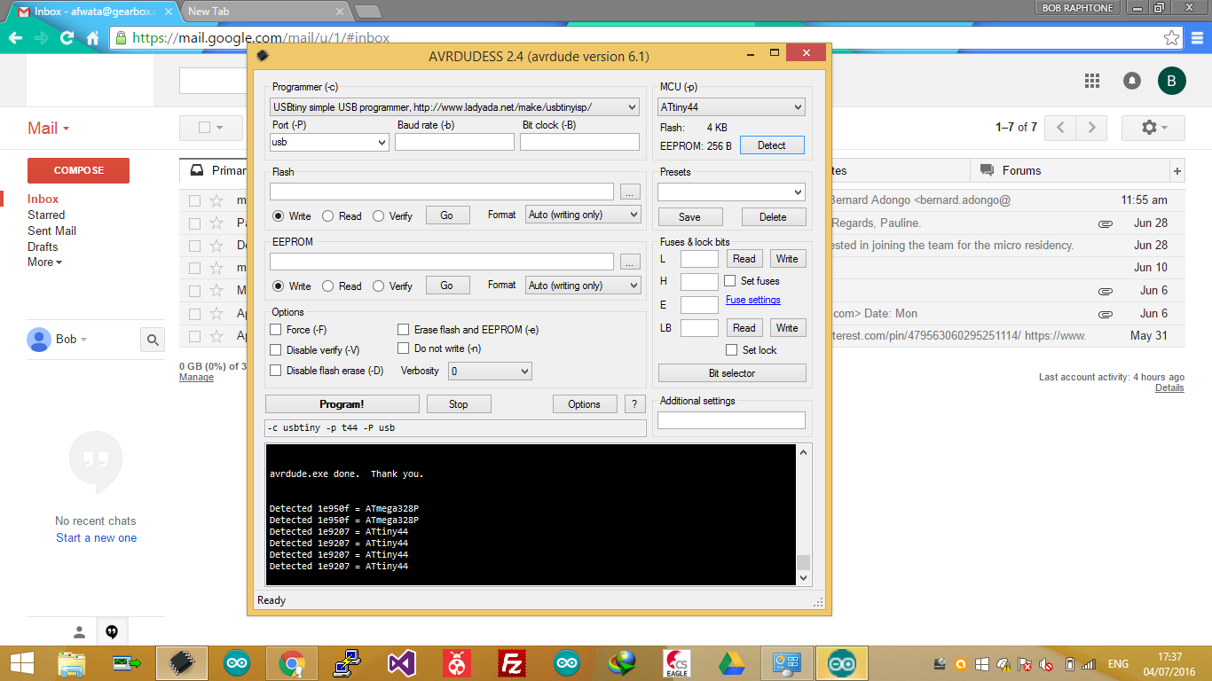
- • In AVRdude, select; Programmer - USB tiny....simple USB......ladyada
- • For port, Select USB and
- • For Mcrocontroller, select ATmega32 then
- • Click detect
On the lower black screen window, you should see the message indicating: Detected=Amega32
Blinking an LED
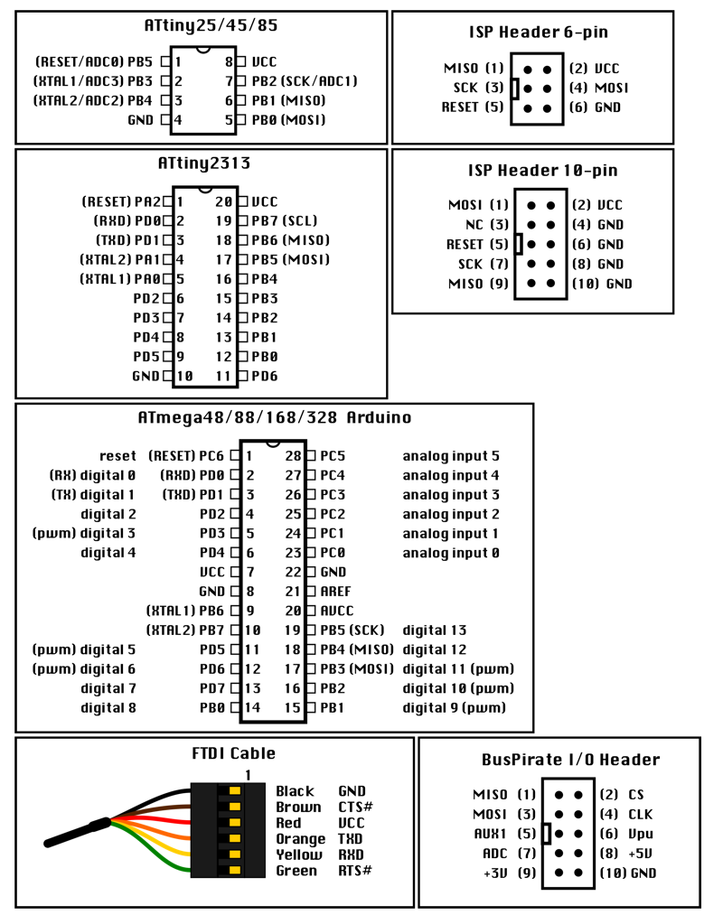
- • Connect LED to pin 14
- • Open Arduino
- • Load the code.
Note: Pin 13 of ATmega 32 is physical pin 20
To upload the code, follow the process below;
- • Go to File and scroll down
- • Select: Upload using programmer
- • Once you load it, LED will start blinking as shown below;
This Video show the lighting and explains the process. By watching it, you will be able to understand more.
Using a Button
Let's connect the button to pin 13 which is physical pin 19
From physical pin
Like LED connection, from the microcontroller physical pin 19, connect to 5V via a 10K resistor and to the button
The button is expected to change the status of the LED lighting when pressed depending on the coding
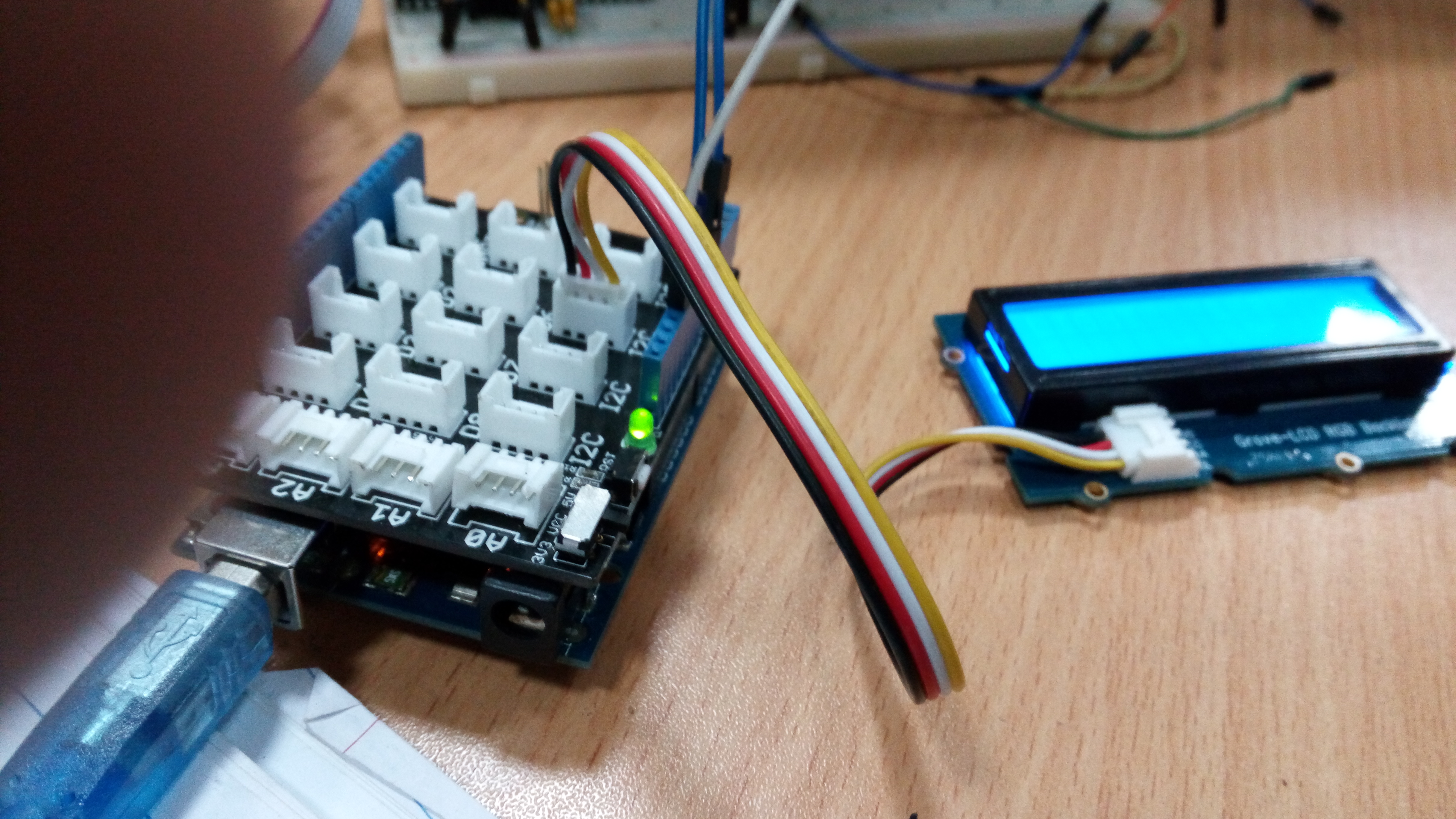
Using LCD as output and LDR as input in Measuring light Intensity and Displaying in LCD(12C)
Connect the LDR to analogue(A0) physical pin 40

- Download the LCD Library
- Unzip the liabrary
- Copy the library to Arduino library folder
- Upload the code below
I now got a problem. I connected the LCD well but refused to work at all. This pusshed me to connect an Arduino to see if it works and true to that, it worked. I tried to troubleshoot it but failed and so just decided to continue my test with the Arduino board
Boards
After the above tests, I managed to do the Fabkit and another board for Light Sensor
Fabkit
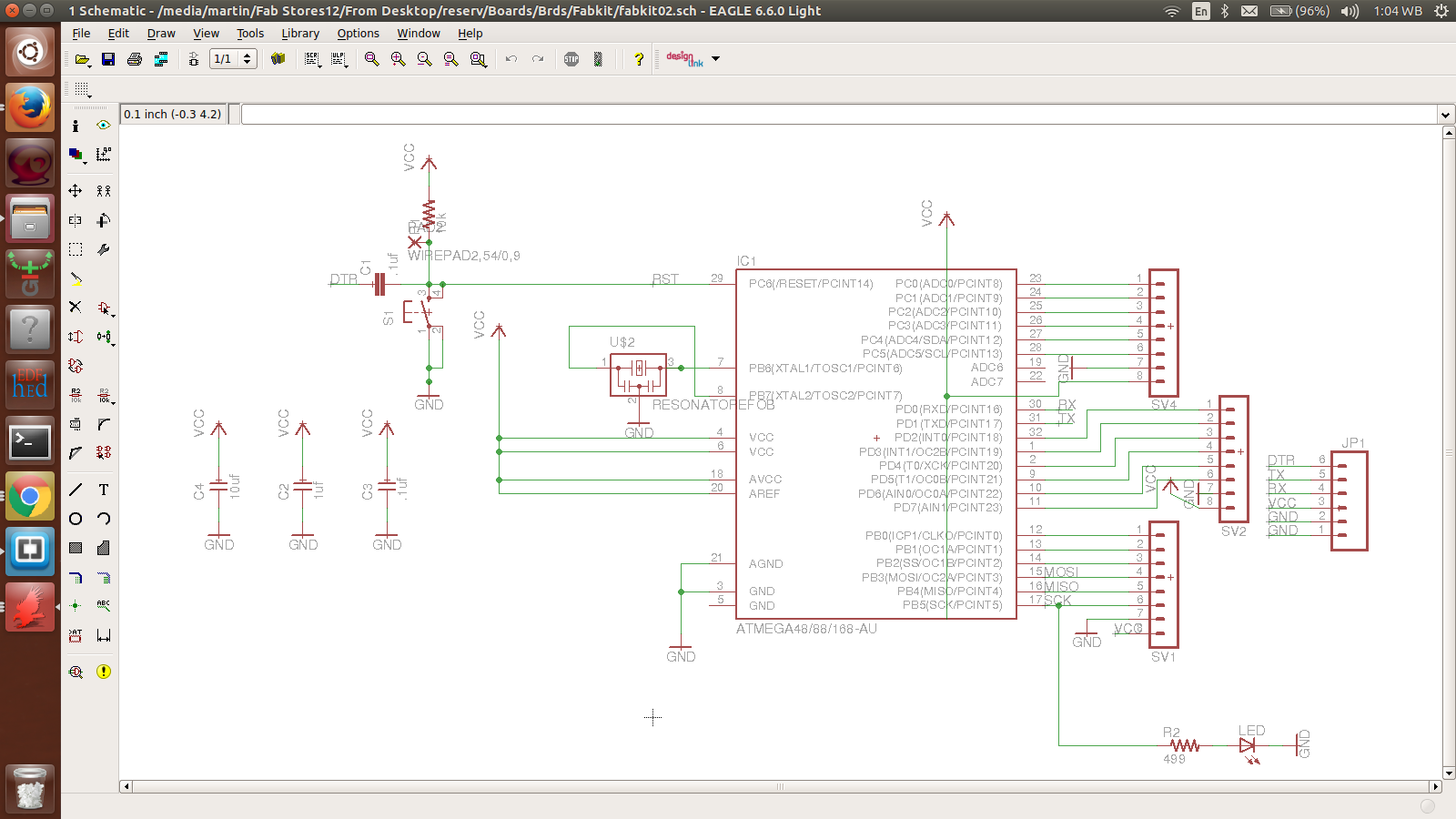
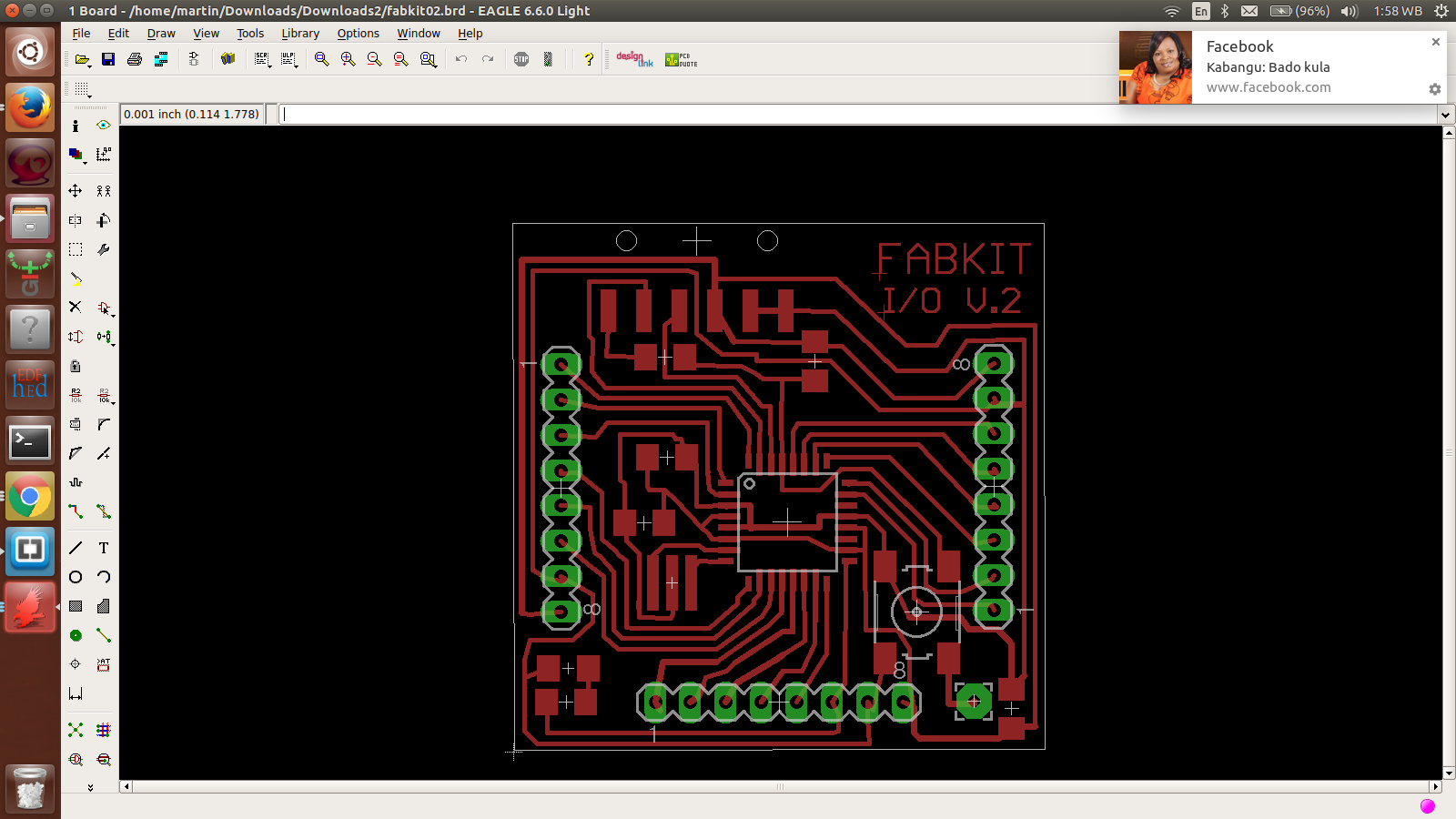
I produced this board; downloaded, etched and soldered. Below were BOMs
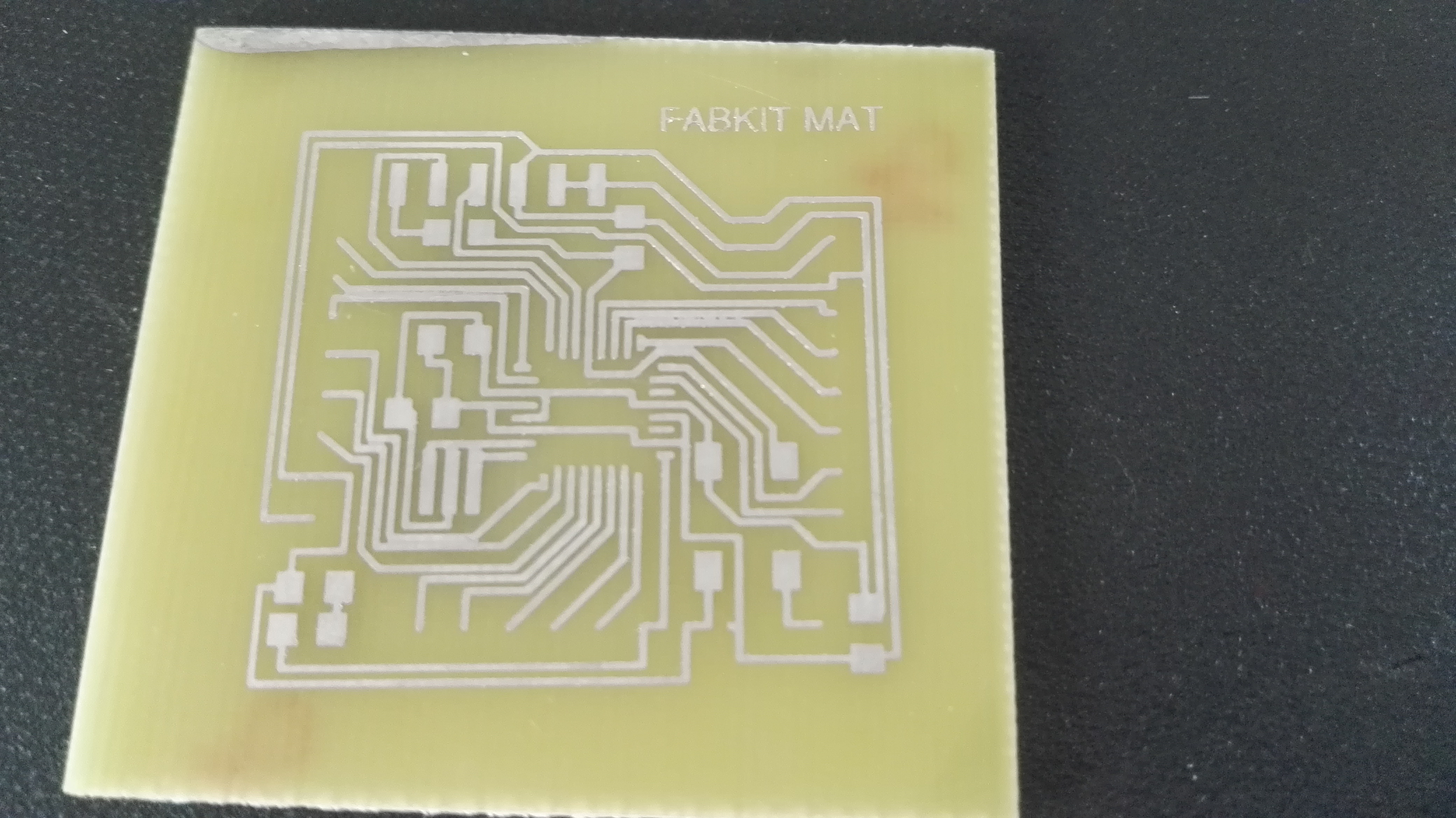
I did this first board so well and decided to do tinning. This would protect the board from faster decomposition. After I cleared this process and was now heading to soldering, I decided to do continuation test. Just before that, using obswervation, I realized that some lines were connected. I tried to disconnect them, I failed and so hard to repeat the production
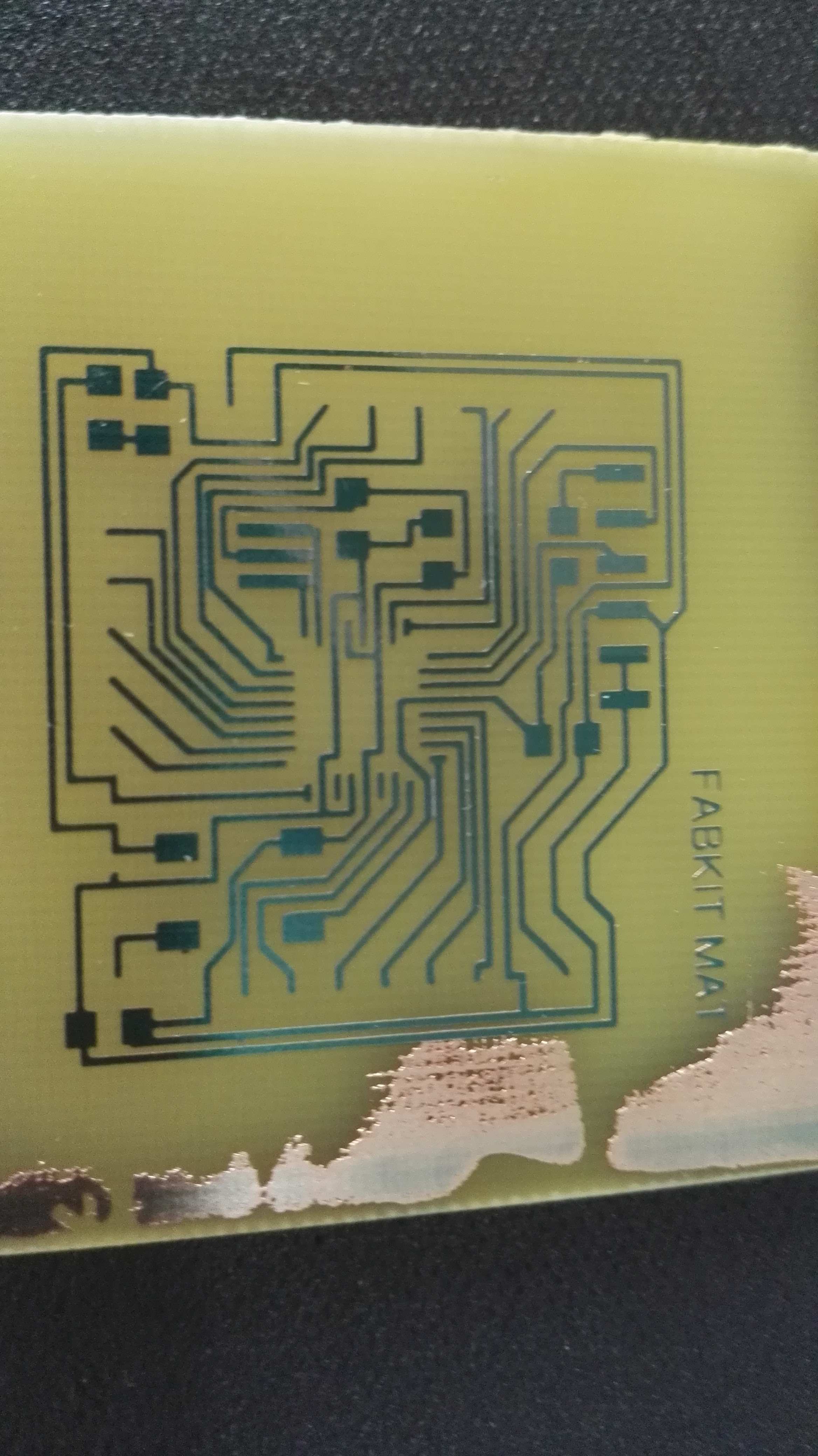
This was my new board I did but on the observation, the problem was still repeated. I checked the design again and it had no problem. That is when I decided to recheck my printed artwork. My alignment was not properly done (I used multiple printed papers to emphasize the darkness).
Fabduino BOM
| PART | VALUE | DEVICE | CASE STYLE | PACKAGE | URL | QTY |
|---|---|---|---|---|---|---|
| IC1 | 8-bit | Atmega328P-AU | 32TQFP | Smd | 1 | |
| R1 | 10K | Resistor | 1206 | Smd | 1 | |
| R2 | 499 | Resistor | 1206 | Smd | 1 | |
| C2 | 10uF | Capacitor | 1206 | Smd | 1 | |
| C3 | 0.1uF | Capacitor | 1206 | Smd | 1 | |
| C4 | 1uF | Capacitor | 1206 | Smd | 1 | |
| C6 | 22pF | Capacitor | 1206 | Smd | 1 | |
| LED | Red | LED | 1206 | Smd | 1 | |
| XTAL | 20Mhz | Crystal | 1206 | Smd | 1 |
I now finally did the best board after the corrections. After the challenges above, I made up my mind not to do tinning but proceeded to soldering
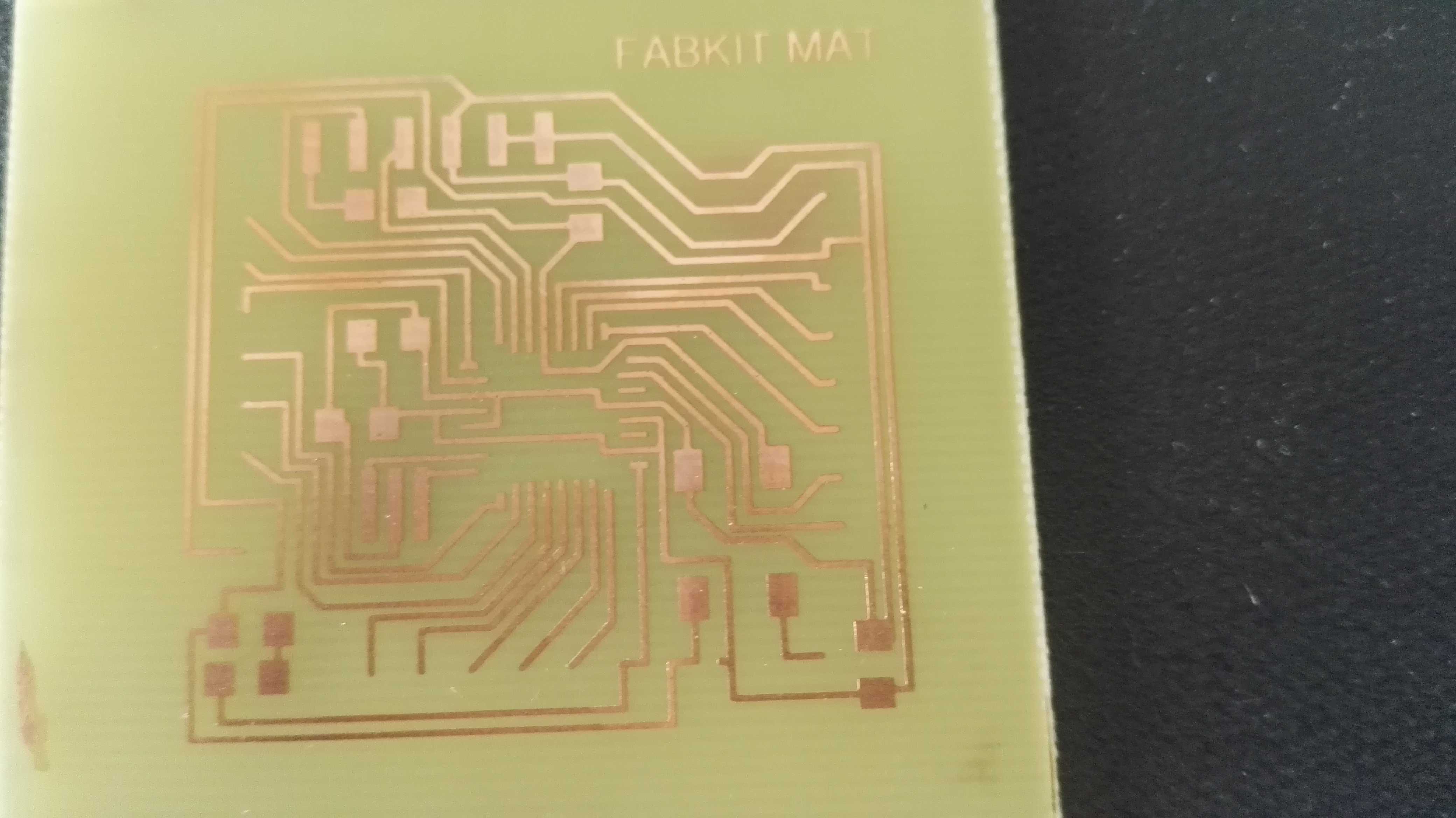
All the same, I never activated the vias and pads layers and so obviously soldering would be tricky.
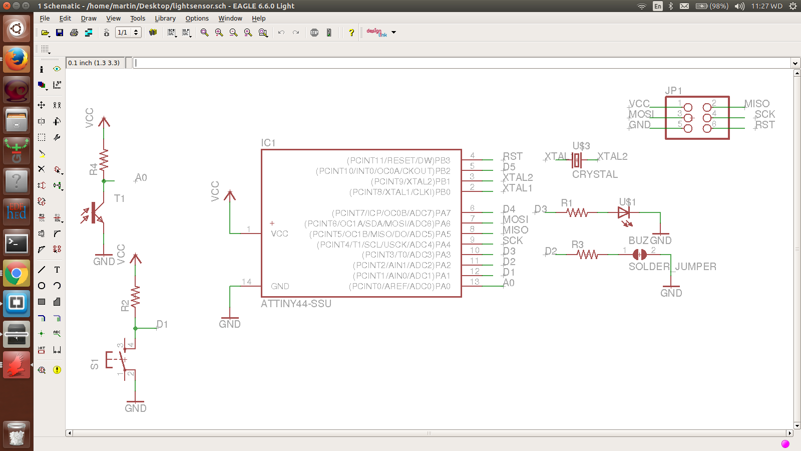
Light Sensor
I decided to design a board with light sensor which would respond to light changes . Then changes would be communicated by lighting
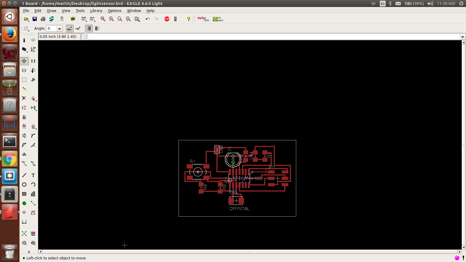
Board production and SOldering
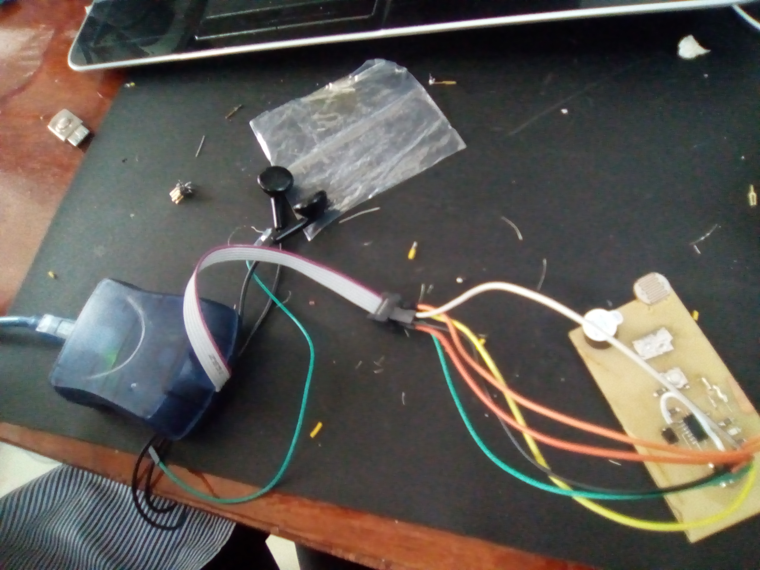
It took me a short time to make this board to completion since it is very basic. I used a light sensor (LDR) and a button to work as input devices. Consiquently, I used buzzer and an LED as an ouput device
Programming
Using AVRDUDES, I managed to first detect the chip, burn bootloader and programme it well
Using the Arduino IDE I was able to detect the microcontroller so well
Here, the purpose of this board is to demonstrate the effect of imput devices. In my programming,the Ldr is will sense light at a value of 251 and now set with a buz which will be on to indicate the result but when it goes below that, the buz quiets. This can easily be understood from the video. The buz stops when a fingure blocks the ldr but makes noise when the fingure is removed
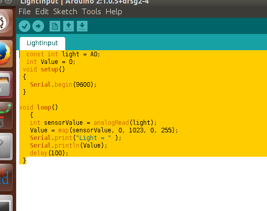
 Light input
            const int light = A0;
                int Value = 0;
            void setup()
            {
                Serial.begin(9600);
             }

            void loop()
           {
           int sensorValue = analogRead(light);
           Value = map(sensorValue, 0, 1023, 0, 255);
           Serial.print("Light = " );
           Serial.println(Value);
           delay(100);
            }