
NOTE: This page has two different Final Project Proposals; ELECTRIC DOOR MAT AND FABMAT 3D SCANNER but the latter is the only one built
My first idear idea was concieved in Gearbox to add an alternative to the neatly pinned carpet on the floor.In order to keep the carpet safe from unnecessary dust from many walk-in visitor and staff shoes, this great idea was born.
Project Objective
To remove dust particles stuck on shoes soles of people entering the room
Concept
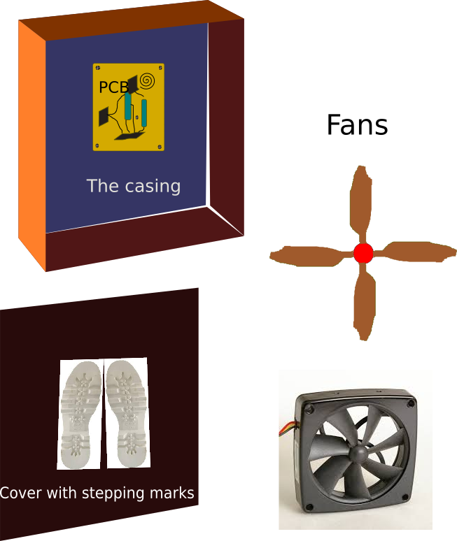
This Electric Door Mat (EDM) is designed to suck dust from the shoes at the entrance. The equipment will be placed on the door way exacly where your door mat is currently. On arrival, you are expected to stand on it for few minutes as your dust are sucked away
By stepping on it, the sensor switch will activate the power on and the the process begins.
How do we do this?
We will use three different units put together to cork as one. These are;
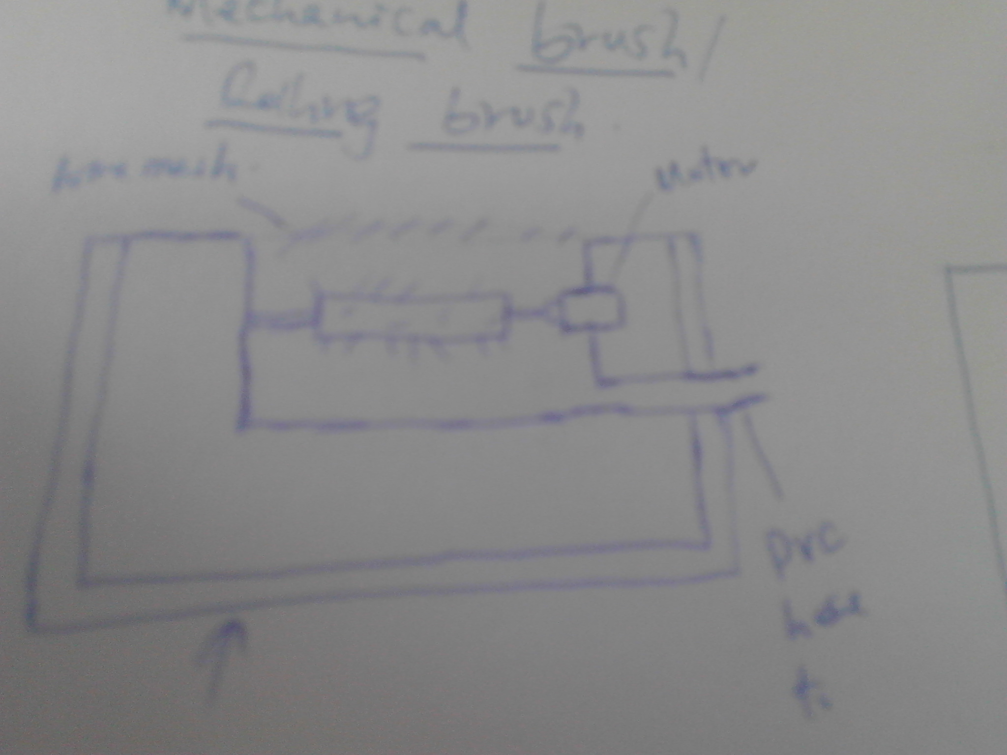
- 1. Mechanical Brush/ Rolling brush
- 2. Suction Unit and
- 3. Dust collection Unit
Mechanical Brush
These will be three in number placed slightly below the foot rest. They are connected to the motor which using a pulley drives other two to make sure that they rotate as they scrab off the the dust.
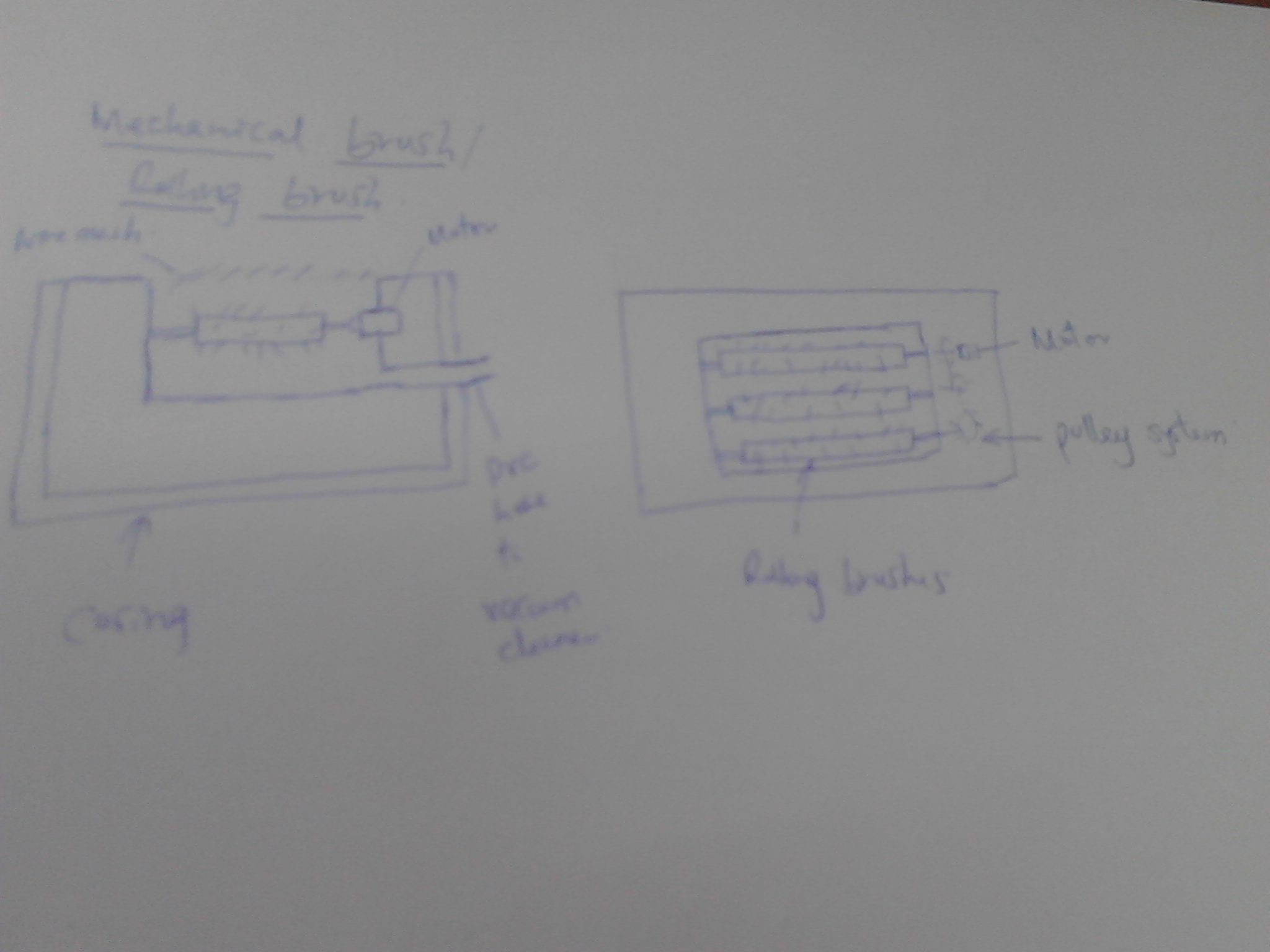
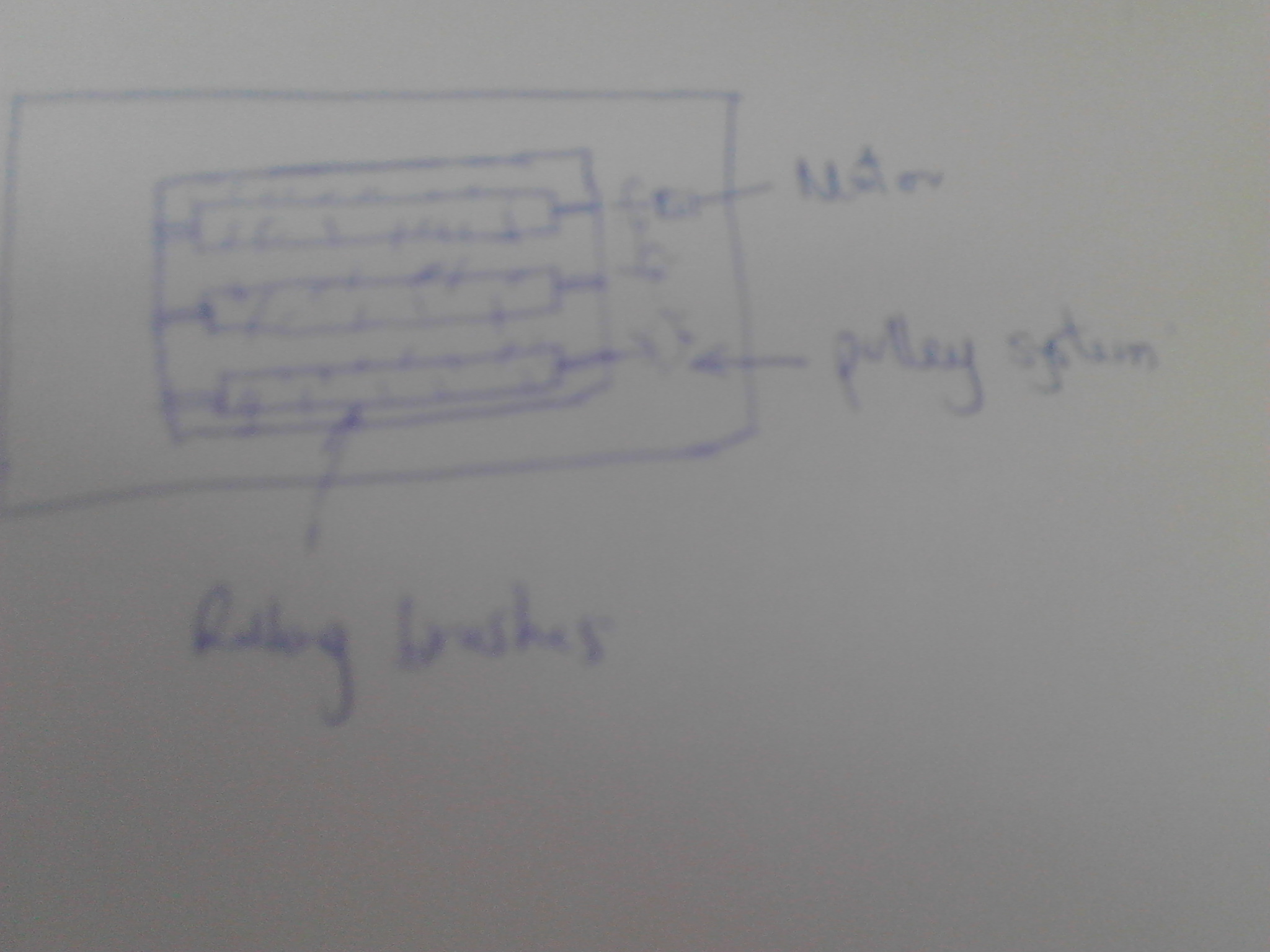
Using the sensor switch, the power which drives the motor which in turn makes the brushes to rotate will be automatically turned on while stepped on
Suction Unit
Here, a vaccume cleaner will be used to effect the process. The Vacuum cleaner will suck away the dust which has been scrabbed of by the brushes. This will take care of the Environmental management which relates to cleanliness and health as well
Dust Bin
This is the dust Collection Point. All the dust brushes ans sucked will be all collected here for disposal at later time.

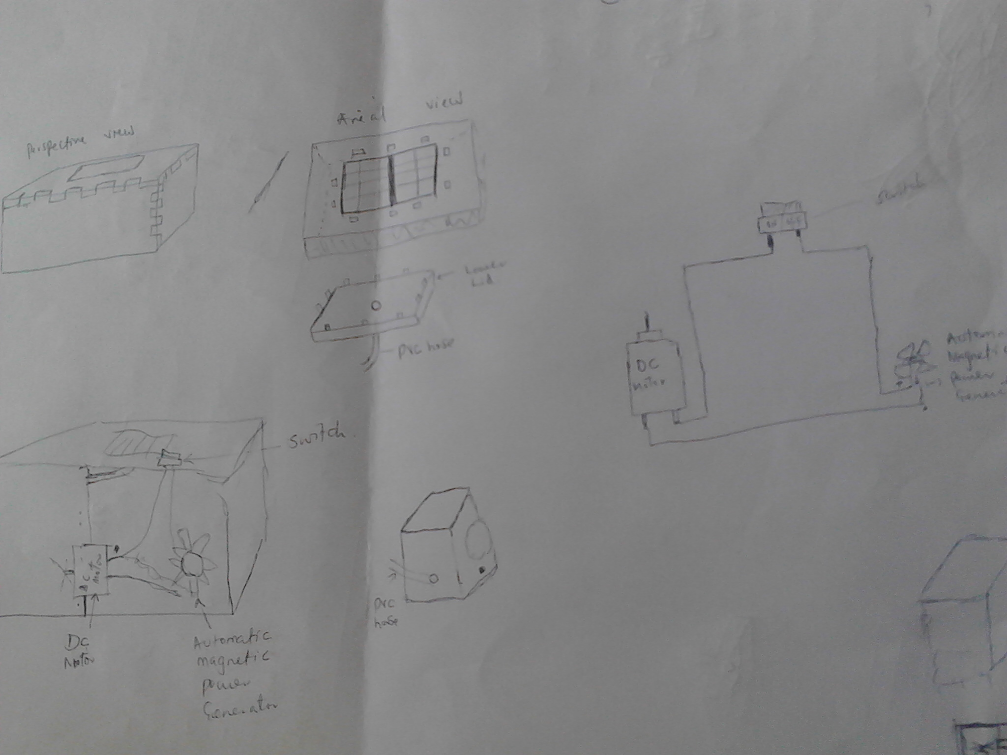
Electric Door Mat Casing Design
The long journey of developing my final project entered an important stage. I had to design the casing but was never sure how since I wasn't comfortable with 3D Softwares. Thanks to my regional Evaluator Luise Calvaro who took his time to take me through Rhino and Onshaape as options to use. He spent alot of his time to ensure that I understand and even gave me assignments. Believe me there wouldn't be any better way. I now had to choose between the two on which one to use. Rhino does not use linux which I currently use most of the time and so this was disadvantaging it Shifting between Windows and Linus would be so hectic. Onshape on the other side is a browser Designing Software.
I also went through alot of tutorials as linked
Onshape Tutorial
Onshape Tutorial
It can be manipulated anywhere provided that you are connected to an internet and this is also what was disadvantaging it due to internet challenges and at times weak connections. All the same it became the tool of the choice. Below are the steps of my design
You need to sign up accordingly with your credentials before gaining access to this software. You then need to sign in, edit the account management and create a Document which you save with a name of your choice
The working area appear with different views, choose a normal sketch view and start your work
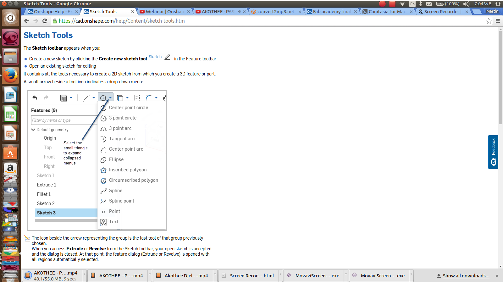
- Click sketch to create youe first sketch. Also a small menu will appear
- Pick a tool of choicefrom the tool bar menu on top according to your design.
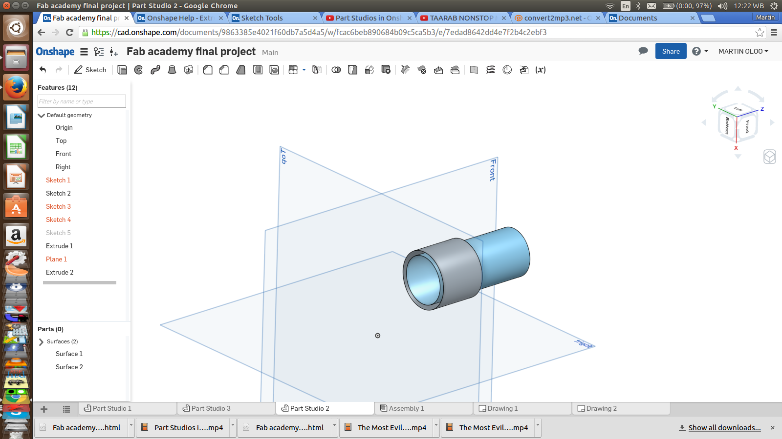
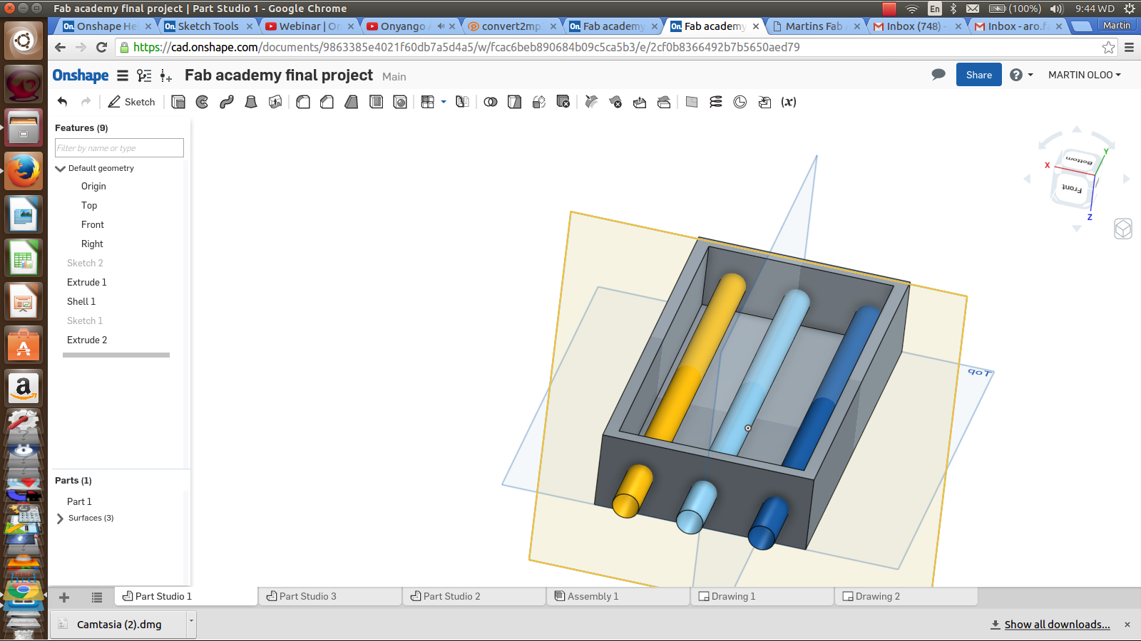
- For this we will design a box with 3 holes and 3 rodes passing through
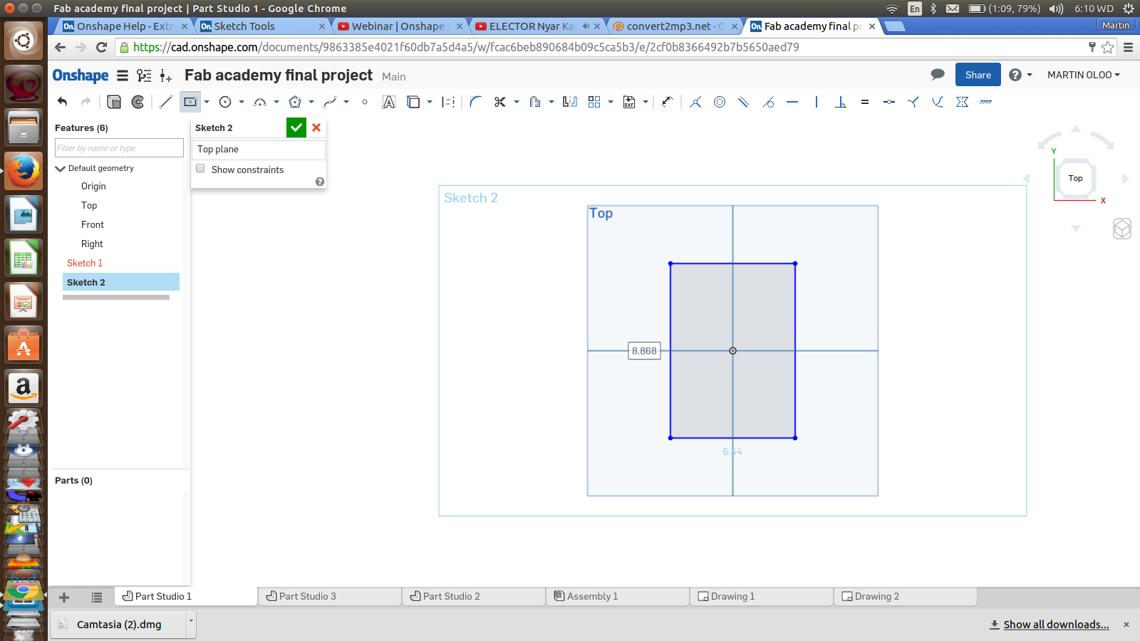
- Draw a sketch of a rectangle and set its dimentions using the dimention tool
- When done, Click the green part of the small menu with a heading of sketch to confirm your sketch
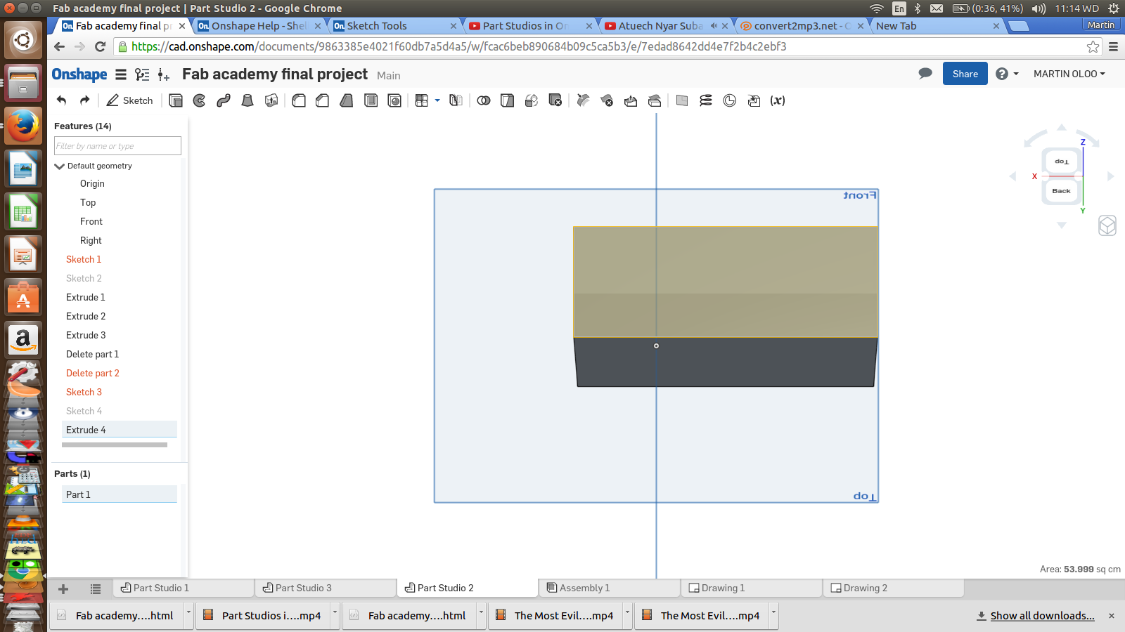
- Select the surface of the object - our rectangle
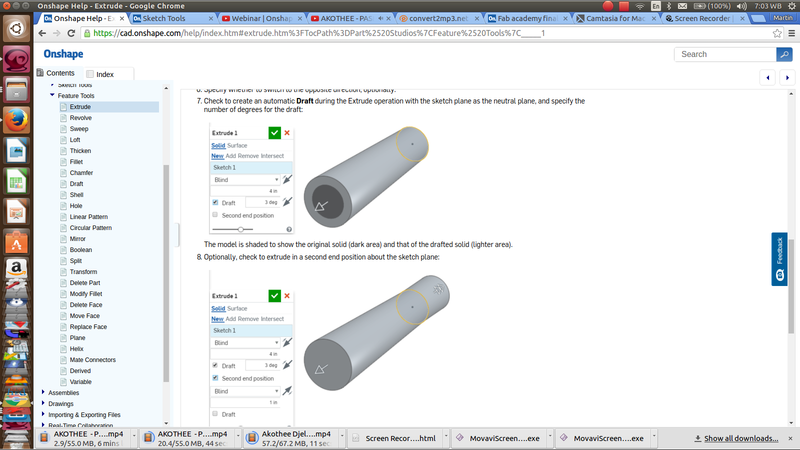
- Now click on the extrude icon. Again the small menu will appear now written Extrude1
- On that menu, select New, for the New Extrude. Also make other selections like dimention to determine the distance of extrude
- You can also use the arrows appearing once you confirm your extrude
- Now change your view to check your extrude
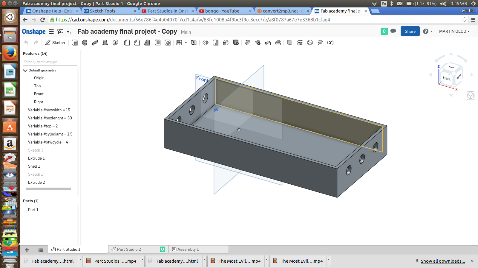
- Again, here, select the surface from which you want to make the shell
- Click on the shell icon.
- On the small menu, enter the thickness dimention which will give uou the wall thickness of the box
- Even before confirmation and after pressing Enter key, you will see the Shell already formed
- We will repeat most of the steps above but we start by creating a New Sketch
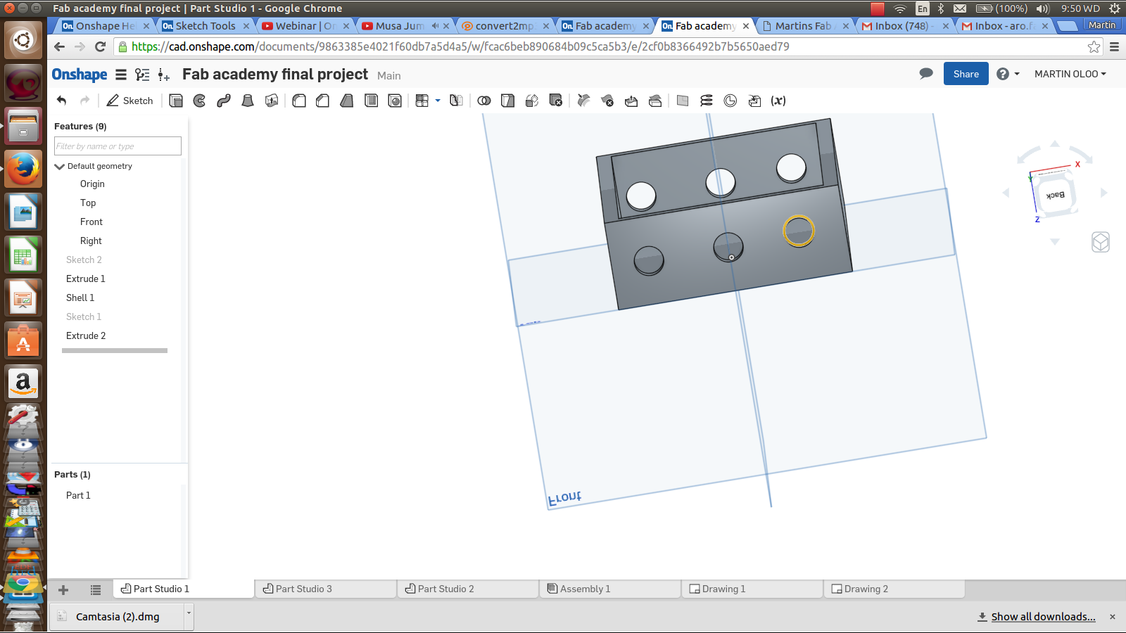
- Take the circle tool to create one cicle on the box side
- Provide settings to ensure that they all appear on the same line with equal distace from each other
- Now repeat the Extrude process to make the hones through
- Set the various dimensions for the cylinder Diameter which is the same as circle diameter, distance between the circles, Distance from the top, Length and Width
- After setting all these, move them on top above the sketch as listed
Onshape interface is made in such a way that it allows you to create different parts in differrent media parts and then has an assembly point where you will assemble all the created parts to function as intended
Part two Media: The rod
Here, the whole process from sketching, through Extrude was followed. However now tools like concentric was now used.
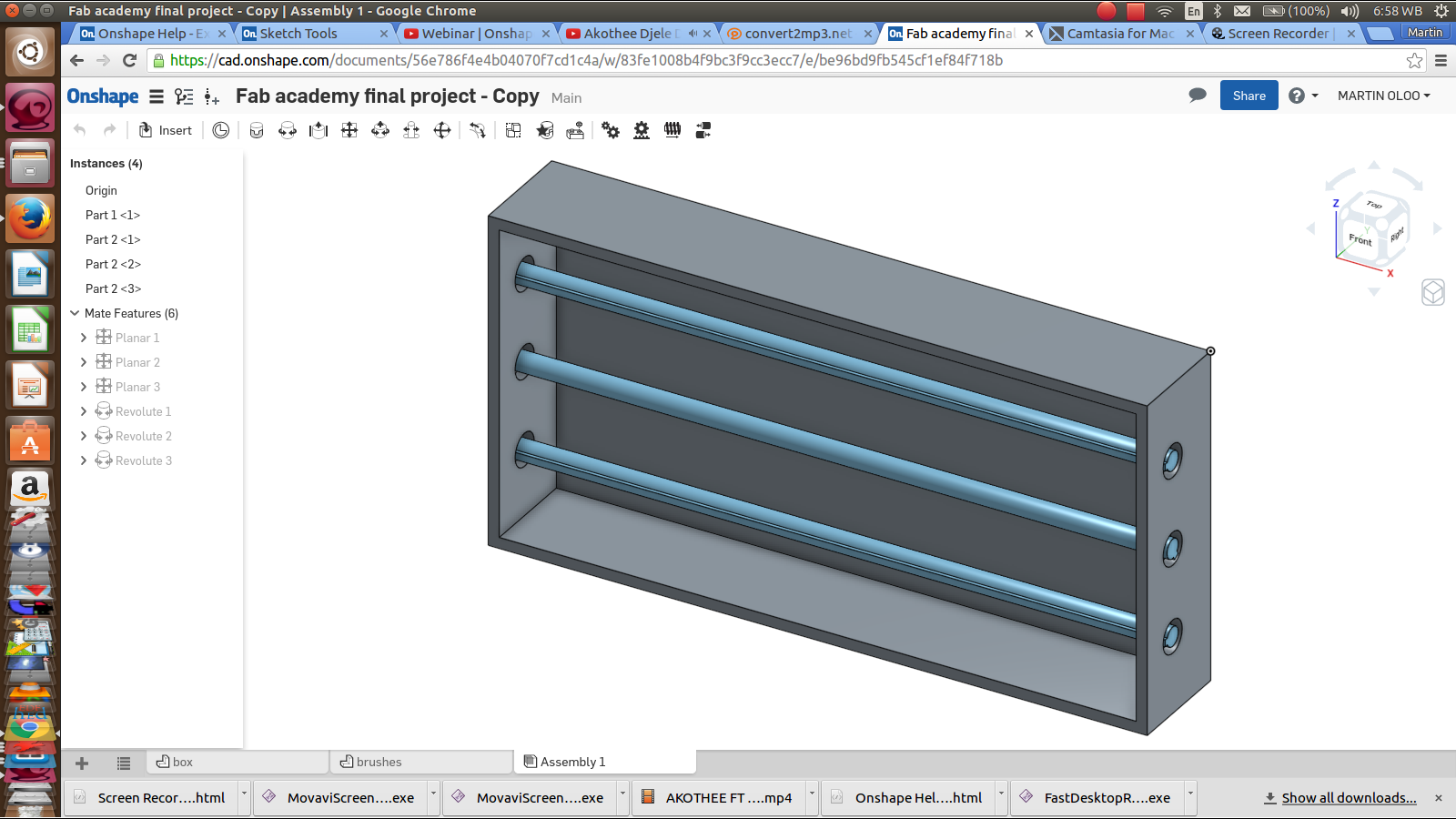
Assembly
On completion of making the required parts, now it is time for assembling the workpiece to see how best it can work
All the parts are inserted into this tab there after necessary settings are donde to make it function. For my case, it was rotation/revolusion
- Use the two Mate Connectors
- Now supply offset
- Provide limitation as needed
- Also create Revolute Mate using the same procedure
- And play
More updates loading....
Change of plan
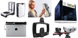
I had to change my initial plan of Electric Door Mat to a 3D SCANNER following some challenges. This was done after extensive consultation with my Remote Instructor - Luis Carvao
Project Purpose
Unlike the initial proposed project which would see solve a simple problem, this 3D SCANNER project fits me so much as a Fablab manager who looks forward to building various machines for the fablab. A 3D Scanner can saves one from alot of designing for 3D Printing
Initially, I did this project during the Machine building week which then worked but with several challenges as earlier stated. I diagnosed the problems, available improvement opportunities and made my recommendations. Below are some of the problems identified and the changes made;
Challenges
- ● Motor drivers heating so much and do not run smoothly
- ● The revolving arm which holds the camera has alot of weight and getting a counter-weight is not easy to achieve
- ● Camera type, size and quality was not satisfactory
- ● Smooth running on the rail i=of the revolving arm
- ● Presentable packaging
Changes and Improvements
I got another opportunity to make various changes on this machine especially after I settled on it as my final project. Below are areas considered and the way they were changed for the better;
Structural/Mechanical
- Main casing changed from the cardboard material to wooden (MDF)
- Object table holder changed from the 3 rod connectors to a metal plate
- Camera holder parts changed from the acrylic material to a 3D printed plastics
- Improvement the balancing weight
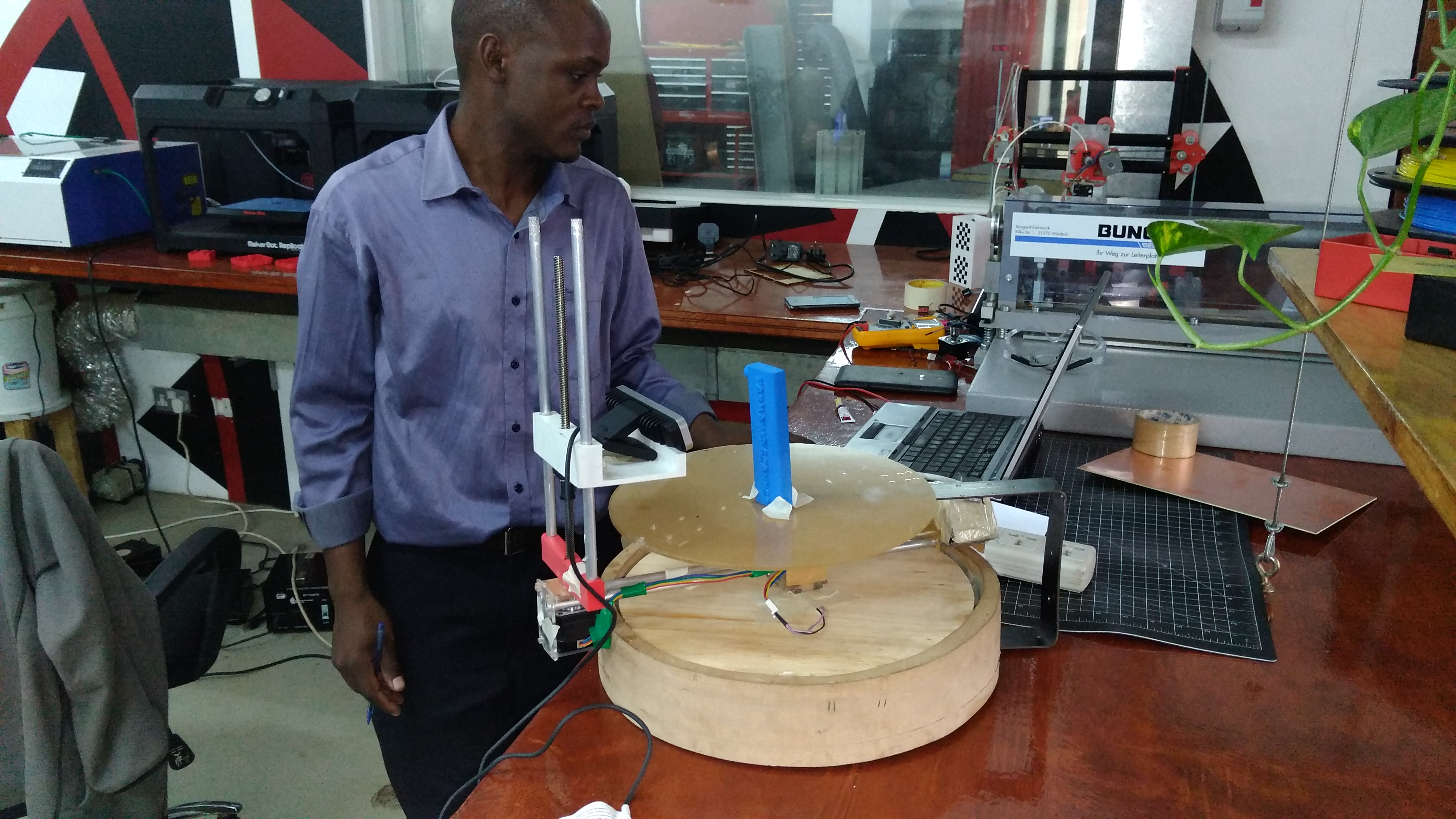
- 1. Base/Casing - this cylindrical body part holding the electronic parts and provides the base for my Machine was changed from the cardboard to wooden parts. I used MDF which I machined in CNC Machine. The weight that this part has also provides for maximum stability needed to hold other parts ansd the camera.
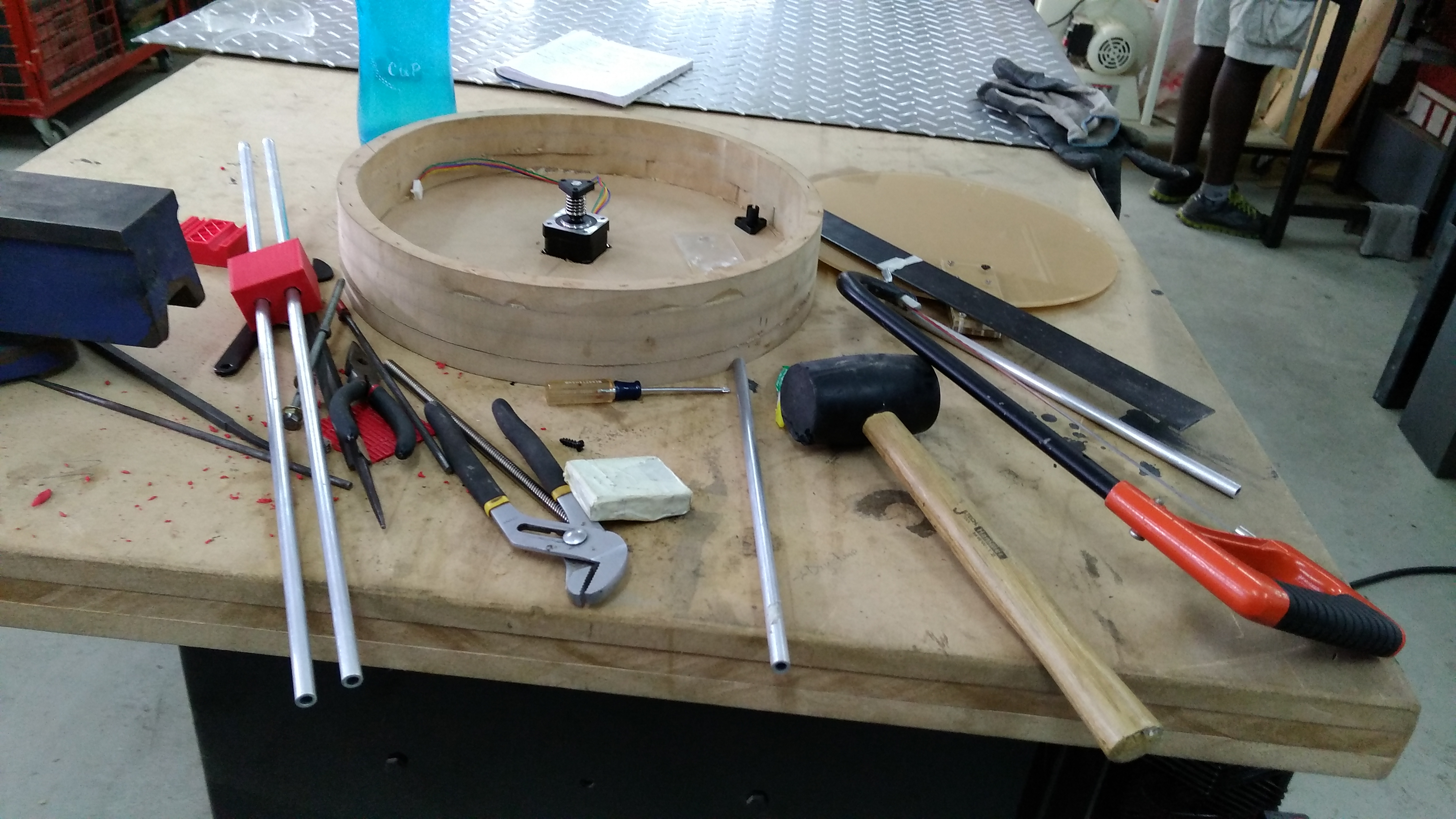
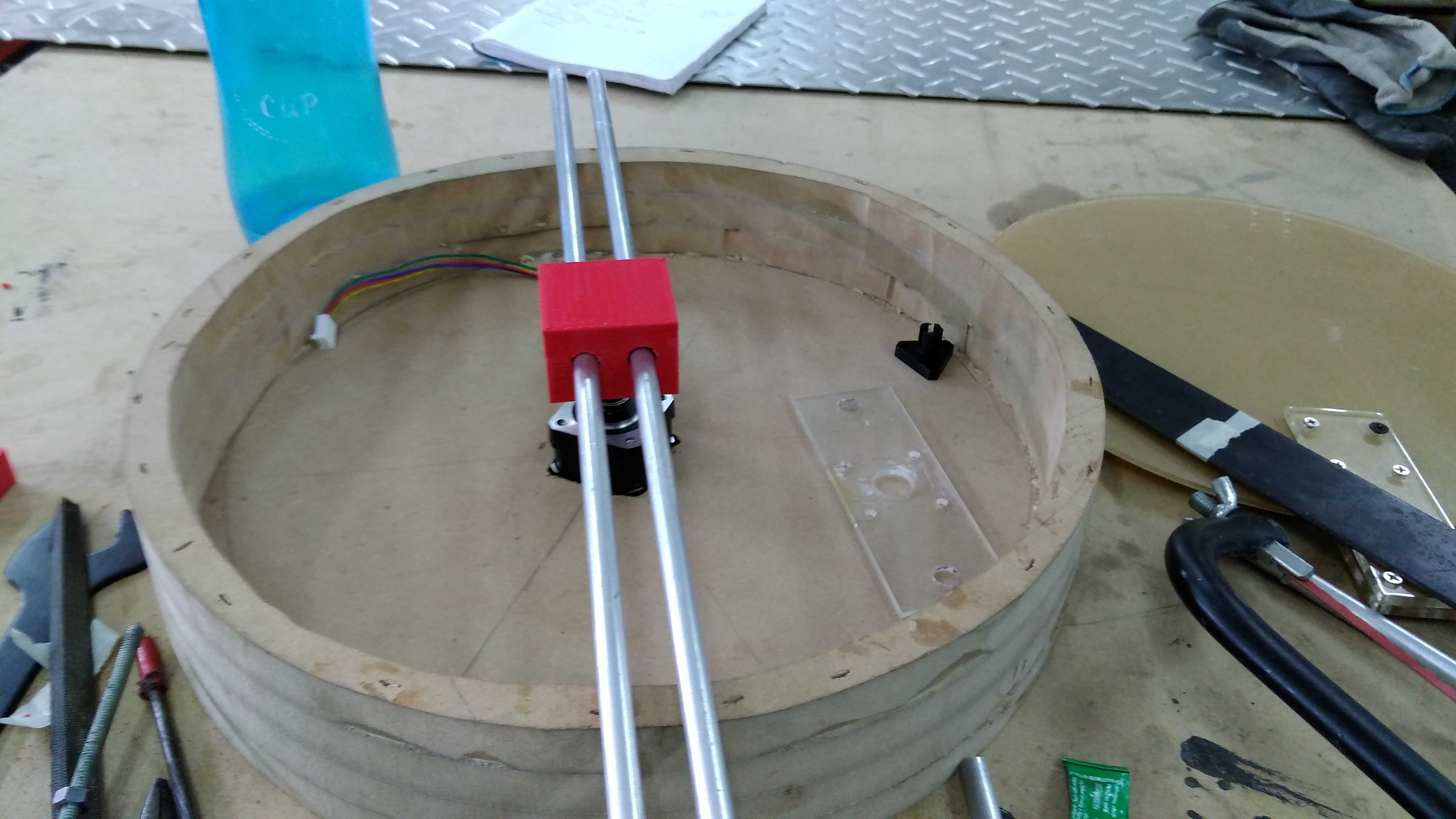
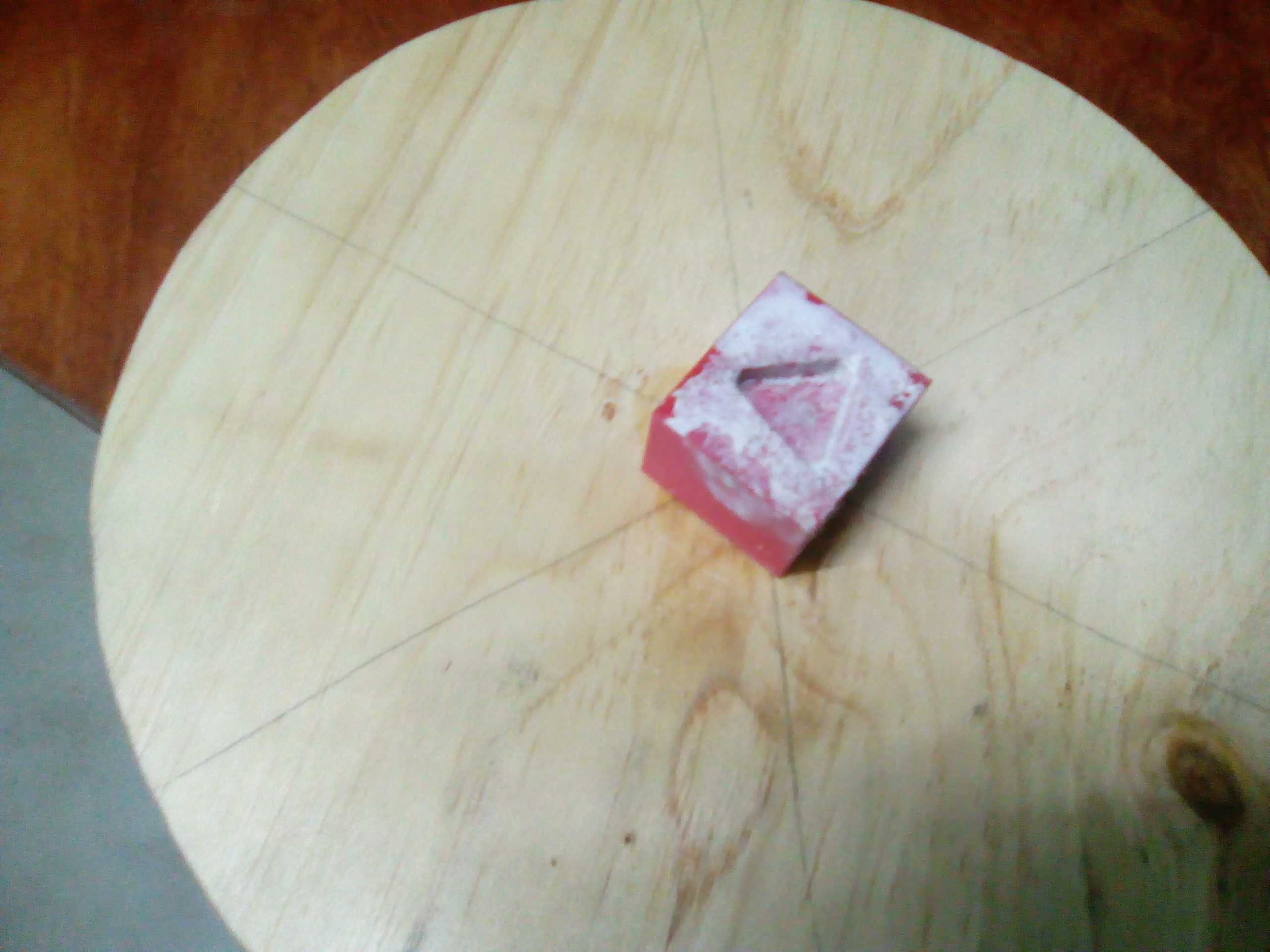
When I realized that the 3D Printed part to be fixed on the centre motor had a slightly bigger and so the motor head was now loose, I used the molding technique to cover the space
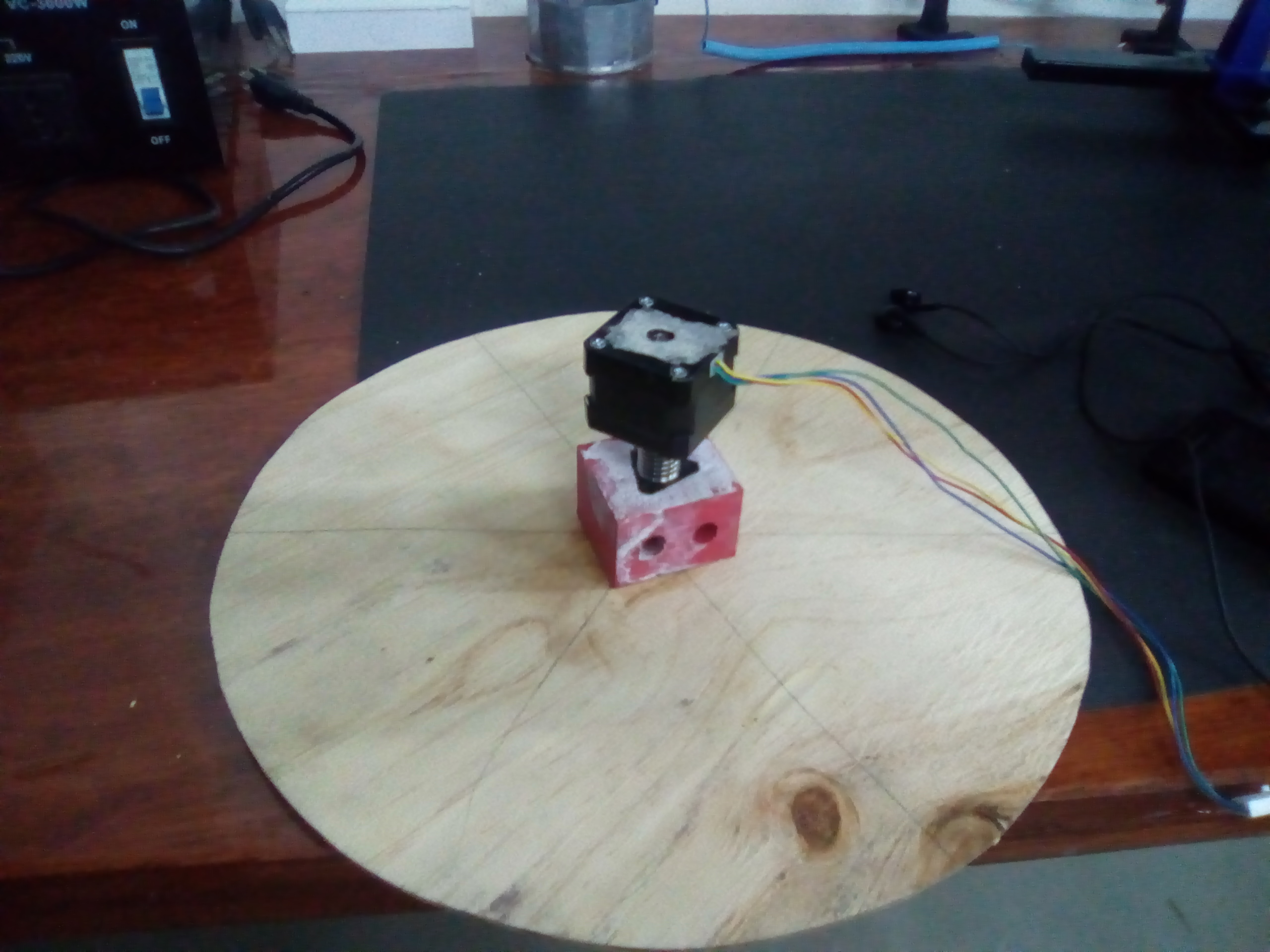
- 2. The Machine modelling changed from the revolving arm/ Camera to stationed camera but allowed the table to rotate
Electronics
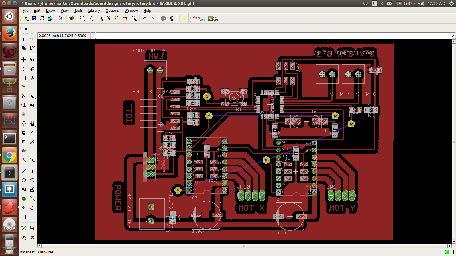
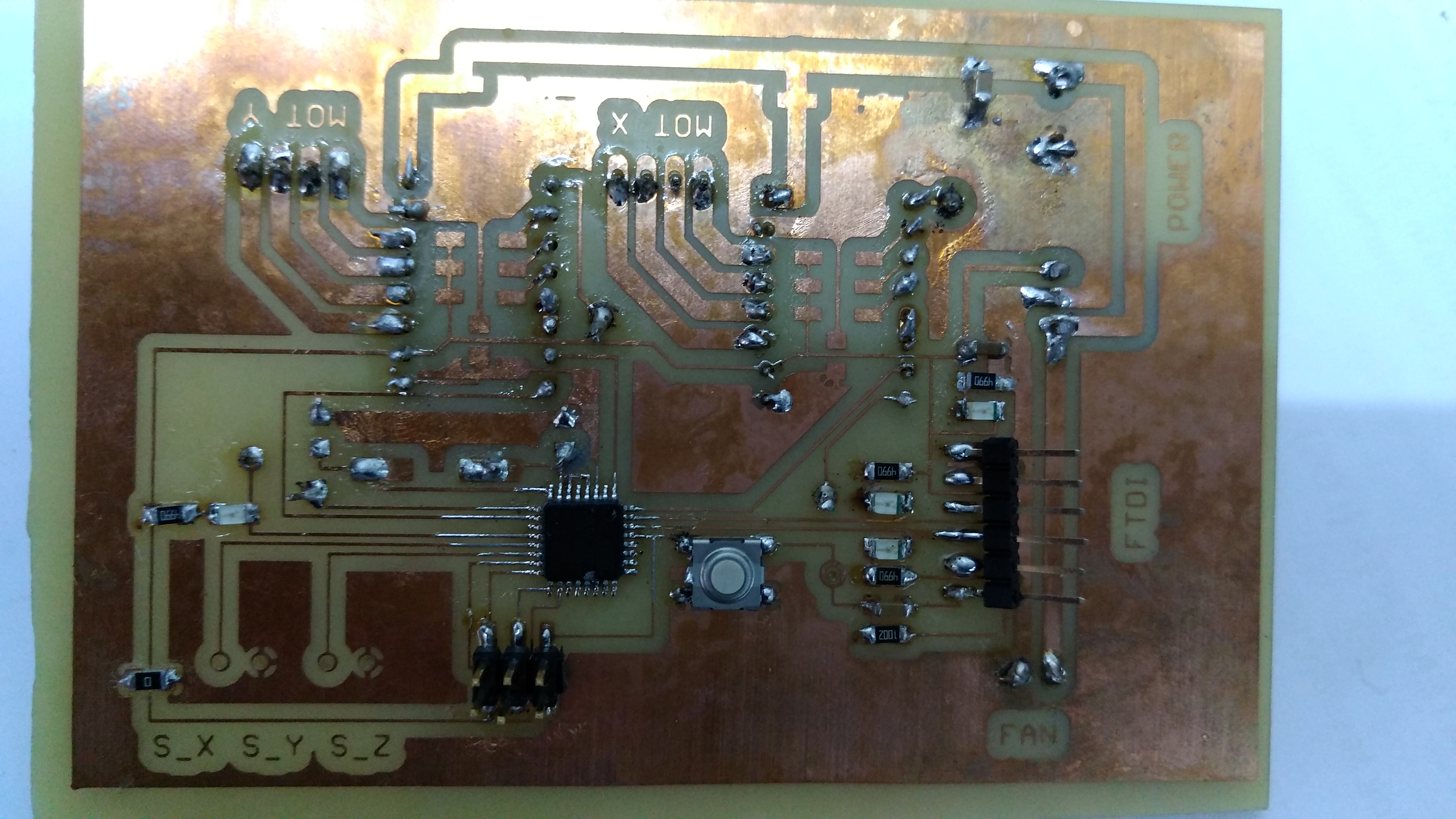
- 3. I designed, fabricated and produce a circuit board which would have the two motor drivers to run the two motors effectively. I used a polythine paper to act as separation material and poured the mixture of the liquid plastic. this worked trully well.
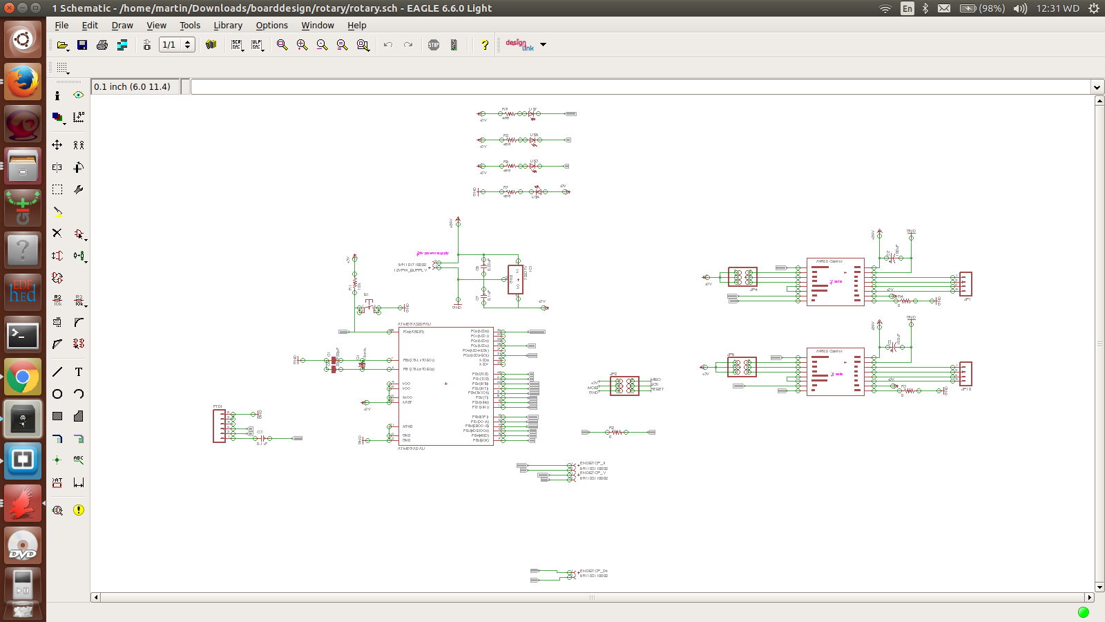
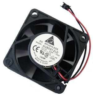
- 4. In Electronics, I introduces a fan which would help in cooling the heating motor drivers
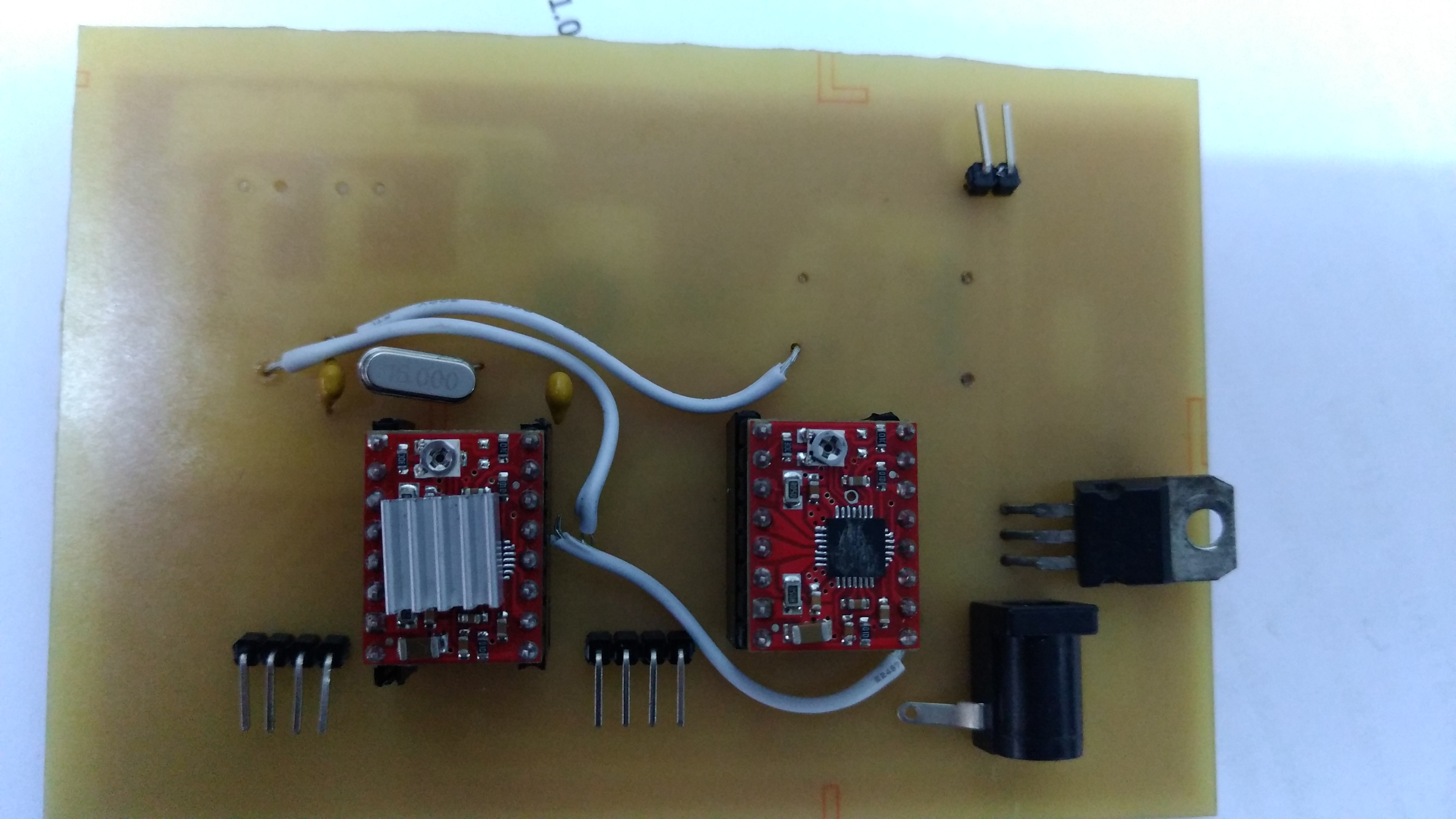
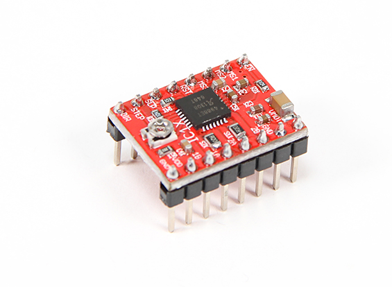
- 5. I also replaced the L298N Motor drivers I used initially to Pololu Motor Drivers
- 6.Casing for the board
Others Accessories
- 6. I changed from the previously used camera to a 3D RealSense Intel camera which has in-built image processing capability. This saved me from other Softwares like COnstructMe or 123D Catch. This camera have multi advantage to my project since it is also small in size and light enough
- 8. I also 3D printed some of the parts like the camera holder from the initial laser-cut acrylic parts.
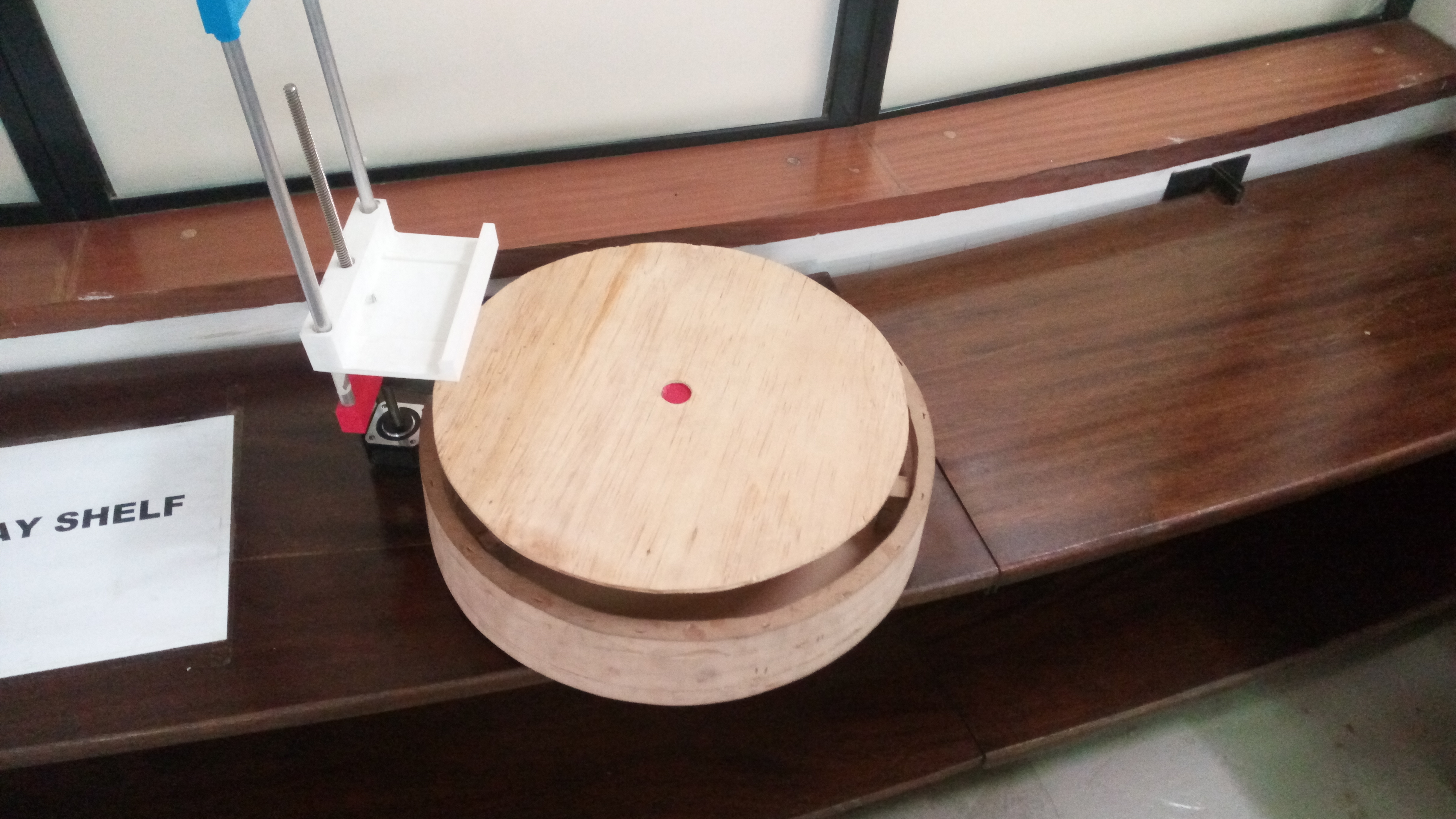
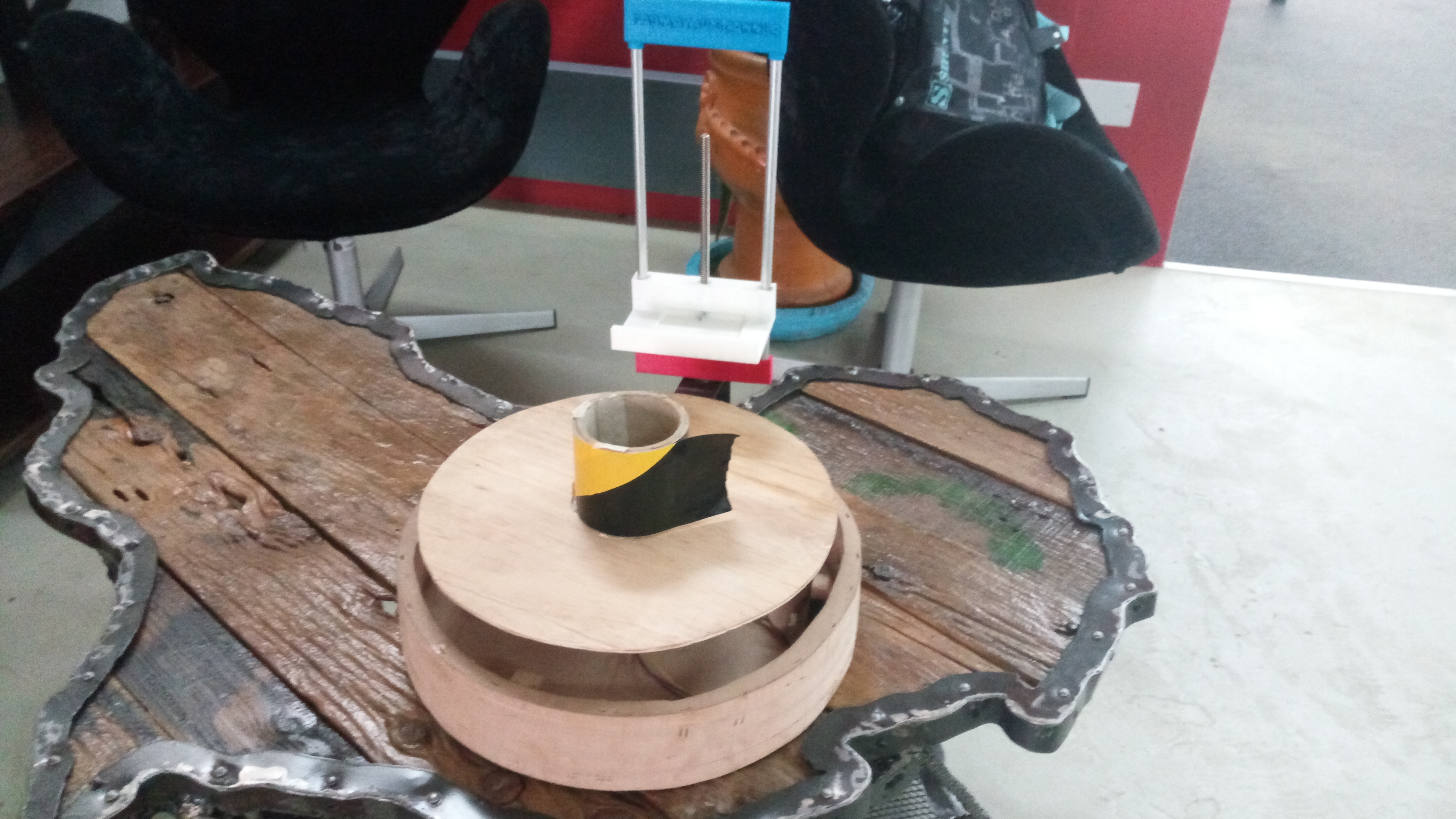
These improvements so far have changed the machine efficiency for the better. The machine packagine is now descent and meets minimum requirements for the fulfilment of the Assignment and Final Project
Final Machine design after the change
Programming
Running the motors and putting into test the machine was the nest big thing. I have to admit that this board sharpened my skills in mastery of electronic rules, practices, components among others. Several PCBs got spoilt at different levels ranging from etching, to soldering, to to connection to power and to programming. This led to fry micrcontrollers, motor drivers and even the arduino chip. This was the most serious learning period and much farmiliarization with electronic rules and components
// defines pins numbers
const int stepPin = 2 ;
const int dirPin = 5;

const int stepPin2 = 3 ;
const int dirPin2 = 6;

void setup() {
  // Sets the two pins as Outputs
  pinMode(stepPin,OUTPUT);
  pinMode(dirPin,OUTPUT);
  pinMode(stepPin2,OUTPUT);
  pinMode(dirPin2,OUTPUT);
}
void loop() {
  Motor1_Up();
  Motor2_Up();
  Motor1_Down();
  Motor2_Down();

}
void Motor1_Up()
{
  digitalWrite(dirPin,HIGH); // Enables the motor to move in a particular direction
  // Makes 200 pulses for making one full cycle rotation
  //for(int x = 0; x < 200; x++) {
    digitalWrite(stepPin,HIGH);
    delayMicroseconds(500);
    digitalWrite(stepPin,LOW);
    delayMicroseconds(500);
 // }
  delay(1000); // One second delay
}
void Motor1_Down()
{
digitalWrite(dirPin,LOW); //Changes the rotations direction
  // Makes 400 pulses for making two full cycle rotation
  for(int x = 0; x < 400; x++) {
    digitalWrite(stepPin,HIGH);
    delayMicroseconds(500);
    digitalWrite(stepPin,LOW);
    delayMicroseconds(500);
  }
  delay(1000);
}

//=======================================
void Motor2_Up()
{
  digitalWrite(dirPin2,HIGH); // Enables the motor to move in a particular direction
  // Makes 200 pulses for making one full cycle rotation
  for(int x = 0; x < 200; x++) {
    digitalWrite(stepPin2,HIGH);
    delayMicroseconds(500);
    digitalWrite(stepPin2,LOW);
    delayMicroseconds(500);
  }
  delay(1000); // One second delay
}

void Motor2_Down()
{

  digitalWrite(dirPin2,LOW); //Changes the rotations direction
  // Makes 400 pulses for making two full cycle rotation
  for(int x = 0; x < 400; x++) {
    digitalWrite(stepPin2,HIGH);
    delayMicroseconds(500);
    digitalWrite(stepPin2,LOW);
    delayMicroseconds(500);
  }
  delay(1000);
}
Areas for Future improvements and Opportunities
My initial plan was to do a scanner with a stationary object holding table but with revolving camera/scanner but for the challenges stated above, the design was changed. This hopefully was expected to solve some problems for example speed in scanning. Matter and Form which I used in 3D Scanning and printing Week, it took about12hours to scan the cap I did. These are some of the problems it would solve
.I am also looking forward to make a larger 3D scanner (human size objects) Scanner especially that currently 3D Printing has gone bigger too.
Lastly, I hope to use this board and this practical to be able to try make machines using motors loke 3D Printers, Milling Machines among others
Files
Motor driving board3D Files