So, this is my second attempt at the final a project and I hope it really works this time :D
Last year I was aiming for a different project but this time I went for a more achievable one.
I started documenting the project while it is half way finished so some details might be missing.
The Idea
The idea here is to create an open-source, cheap and fabricatable digital microscope using common components that can be found easily.
The work here is based on the paper titled "A portable low-cost long-term live-cell imaging platform for biomedical research and education".And is a part of a new paper by Mira A. Okasha titled "An Open-source low-cost Digital Microscope for Monitoring Biological Specimens".
Philosophy
The idea here is to make the project using components that aren't hard to find so that it can be replicated by anyone using a common set of cheap components and a laser cutter or a 3D printer.
There will be 2 versions of it : laser-cut and 3D printed
Approach
I started by designing a laser-cut version using plywood. Why you say?
Pros:- Cheap to develop with.
- Flexible.
- The system can be somehow unstable as the thickness of the sheet isn't always fixed as plywood can be affected by humidity and from manufacturer to another.
- CAD designing for 2D plains requires a lot of work.
So, I decided to go with laser-cutting as a starting point as I find it the most appropriate form if I want to develop this project as a kit.
Afterwards I will develop a 3D-printed version which will be more stable (I hope).
The Science
The Optical Microscope
https://en.wikipedia.org/wiki/Optical_microscope
- Eyepiece (ocular lens) (1)
- Objective turret, revolver, or revolving nose piece (to hold multiple objective lenses) (2)
- Objective lenses (3)
- Stage (to hold the specimen) (6)
- Light source (a light or a mirror) (7)
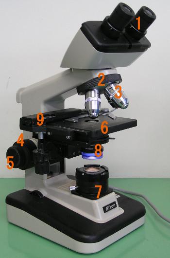
So, the intention here is to create something similar to this so that the eyepiece will be on top of a raspberry pi camera module then the eyepiece lens and then one of the objective lenses. After that the specimen will be on a stage and then a light source.
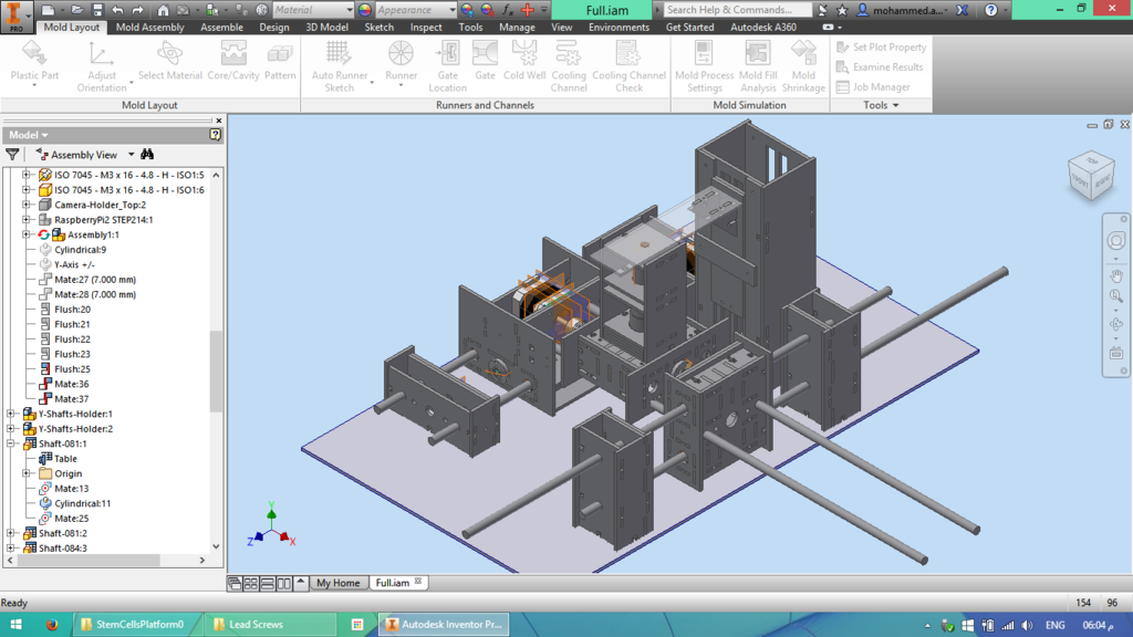
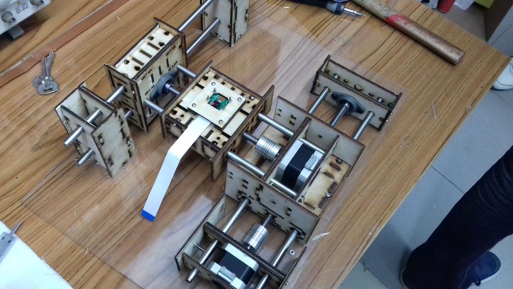
The Design
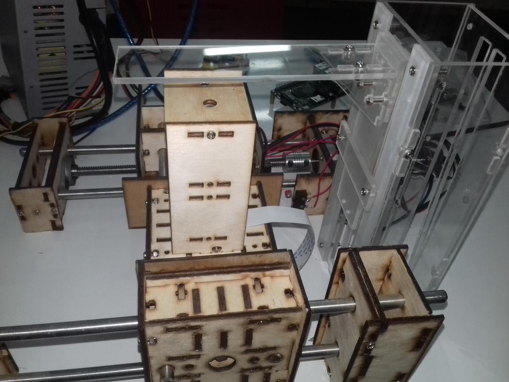
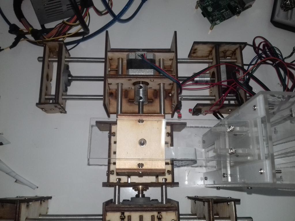
So I started the design for the laser cutter:
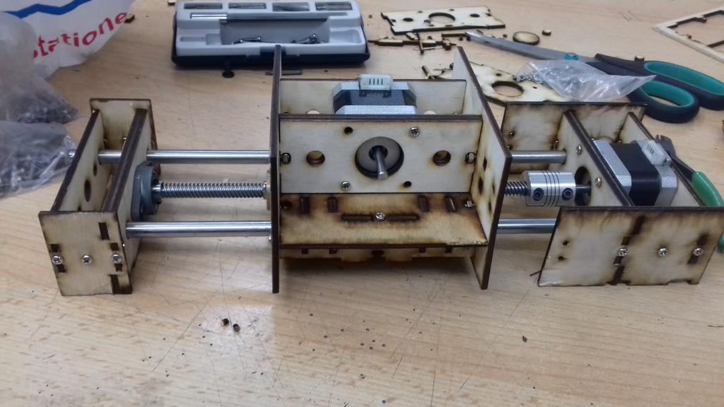
The housing for the X-axis motor:
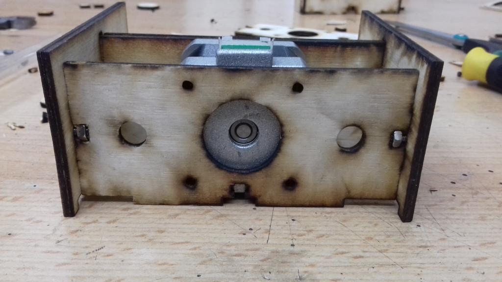
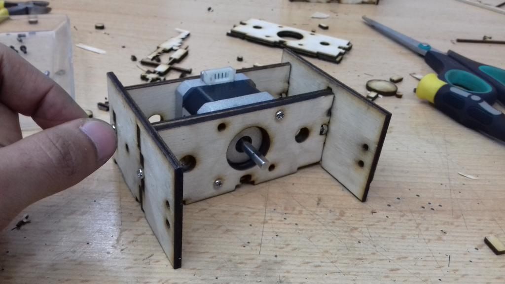
The anchor for the X-axis:
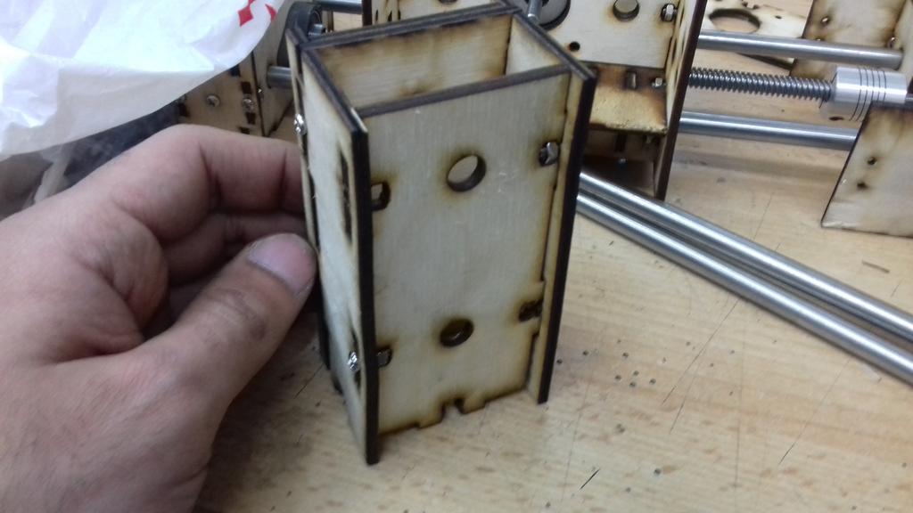
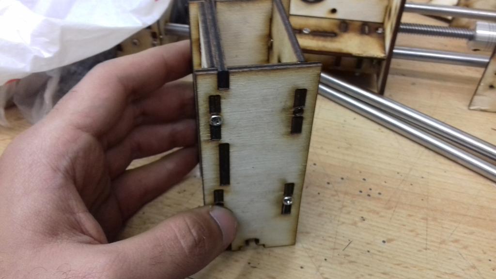
The housing for the Y-axis which is driven by the X-axis motor:
The X-axis assembled
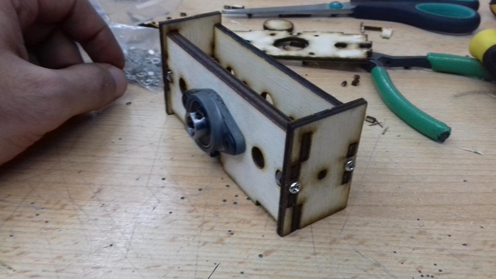
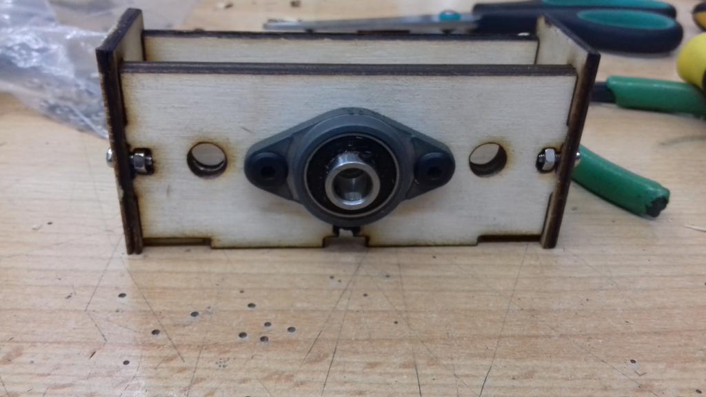
The-X-axis shafts holder
The anchor for the Y-axis
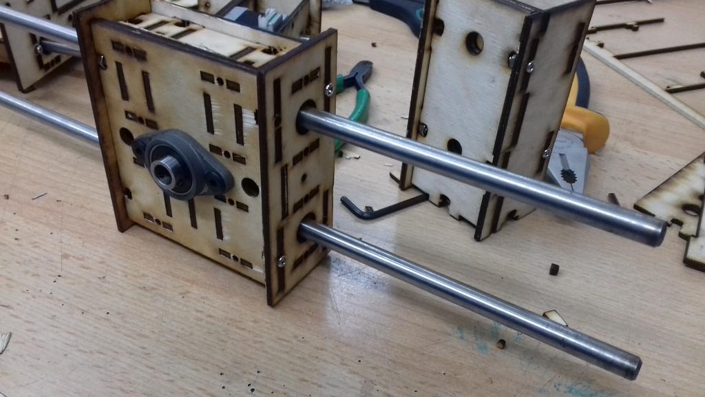
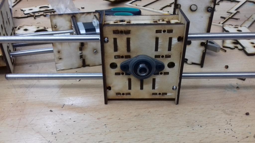
The Y-axis anchor assembled with the X-axis shafts holders
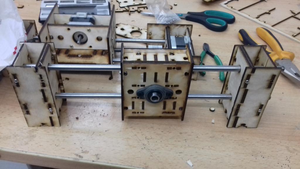
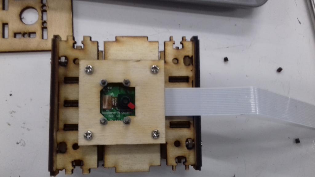
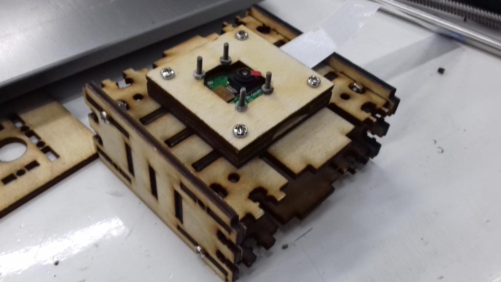
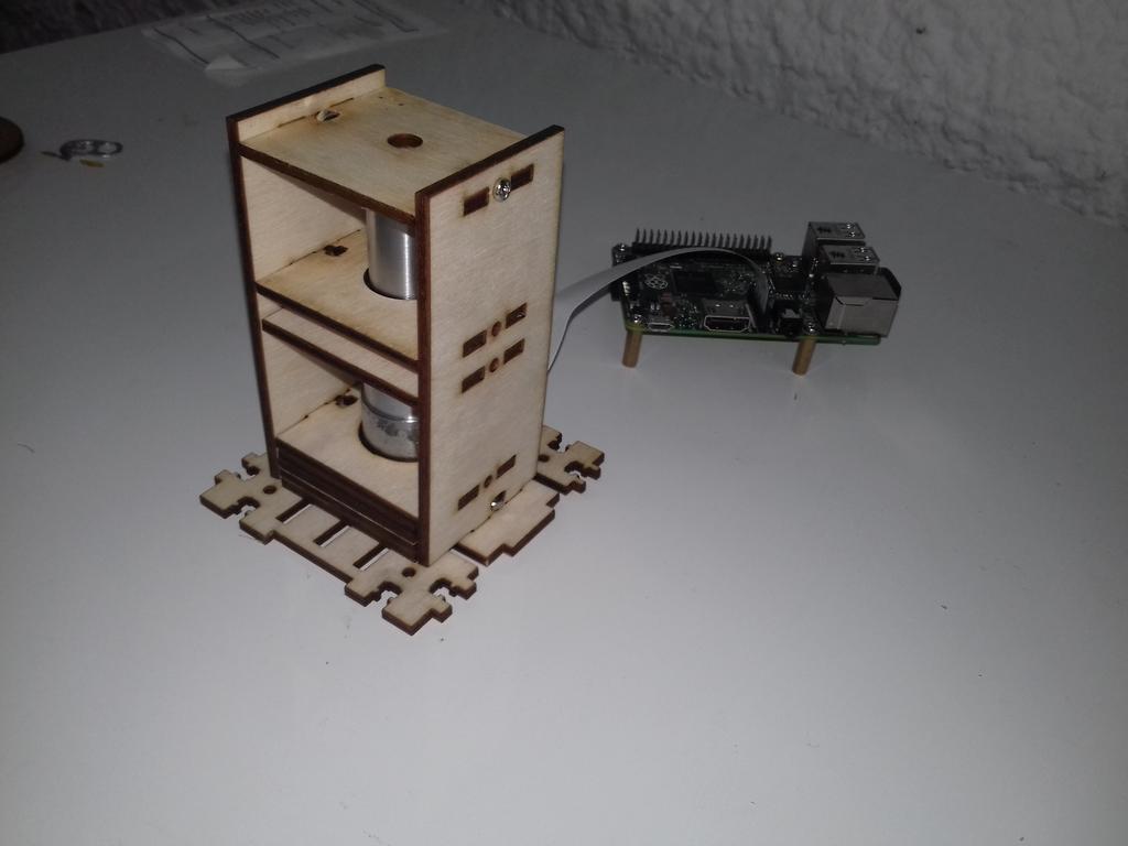
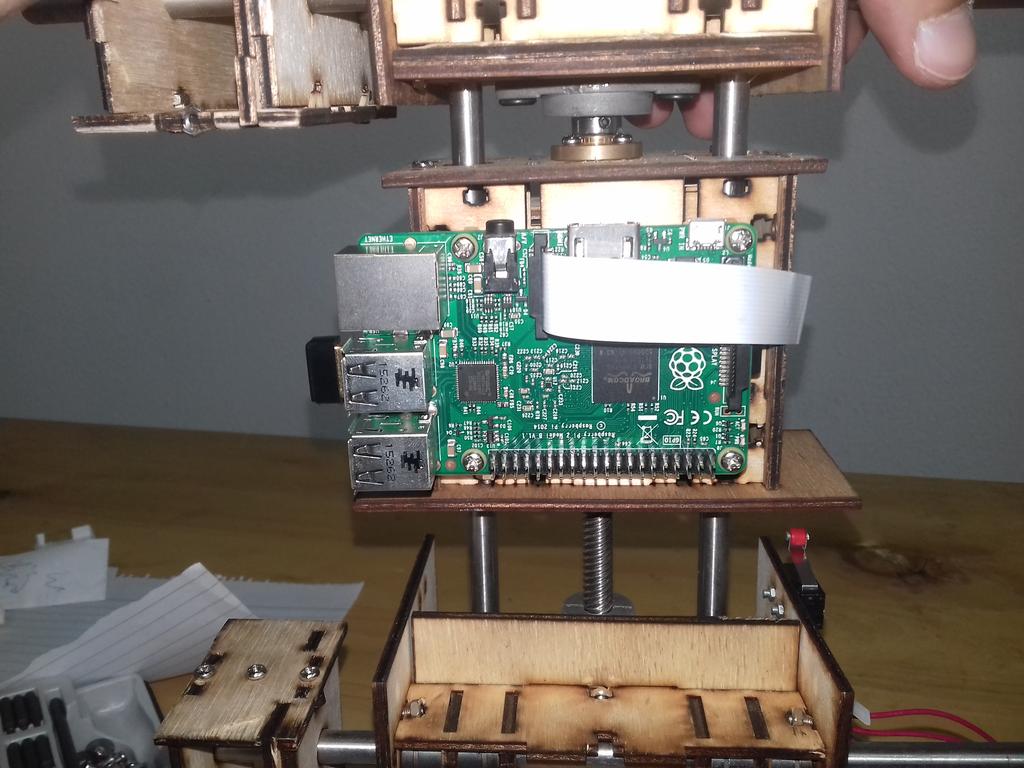
The Raspberry Pi board and camera board holder
All assembled on a sheet of acrylic that acts as a base
Then I attached the GRBL Shieldto control the motors using G-code which I sent using Universal G-Code Sender.
After getting familiar with GRBL, I tested the range of motion of the machine
As you may notice it is so noisy. I found out that I need to change the configurations of GRBL mainly the acceleration settings.
So, I changed those and created a g-code file that create a snake-like scanning movement to test it.
Then I added limit switches at -X and -Y for the homing cycles
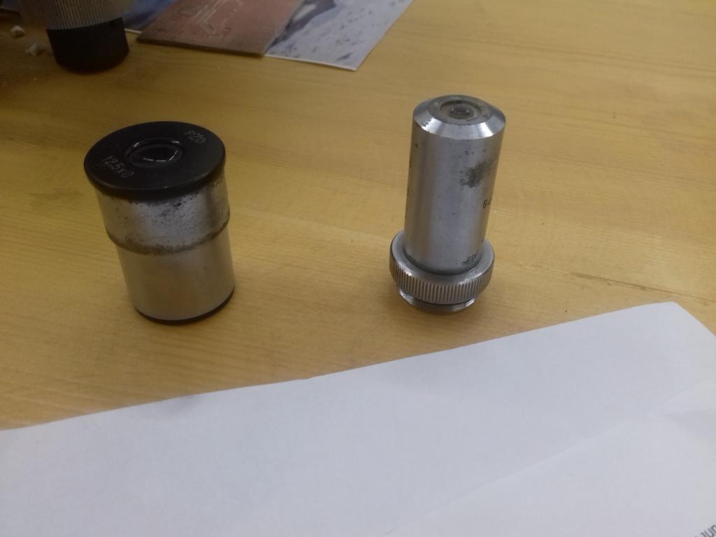
I got my hands on an old PZO binocular microscope which I tore apart to better understand how it works and see what parts of it I can use.
So, I took out the eye-piece lens and the 10x objective lens
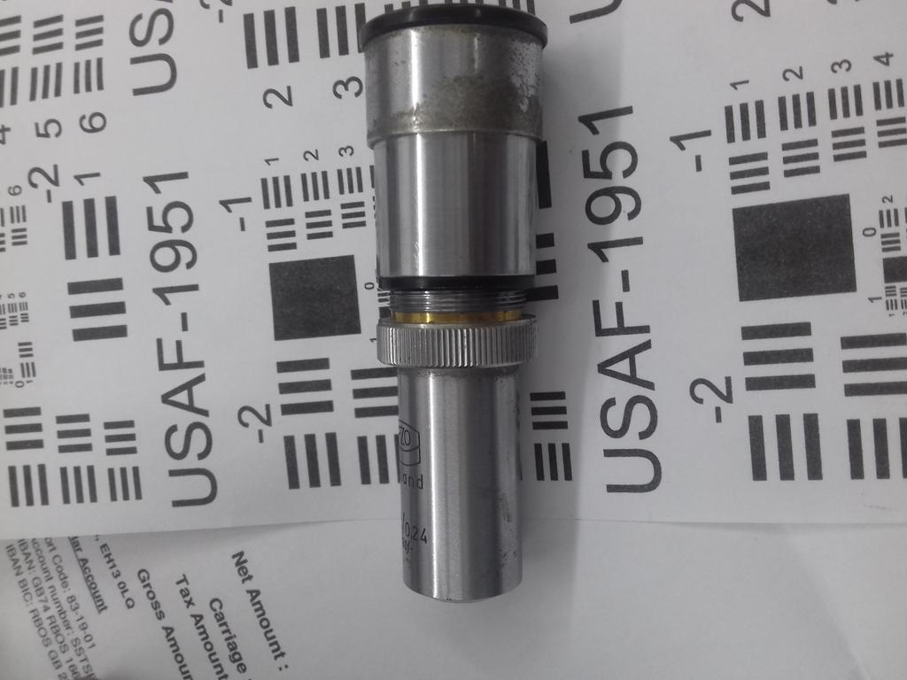
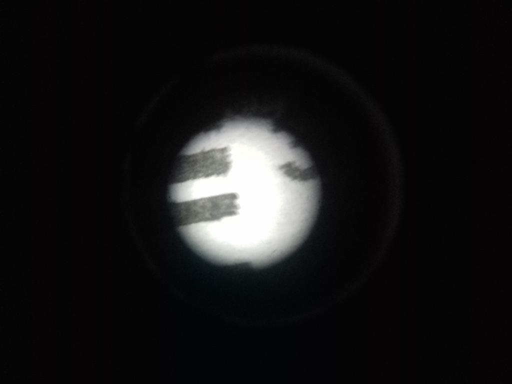
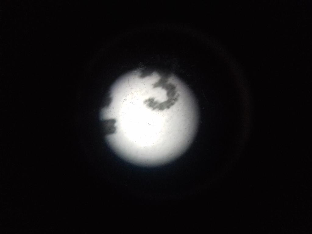
To test the optics of the machine I used the 1951 USAF resolution test chartwhich I used to test the optics.
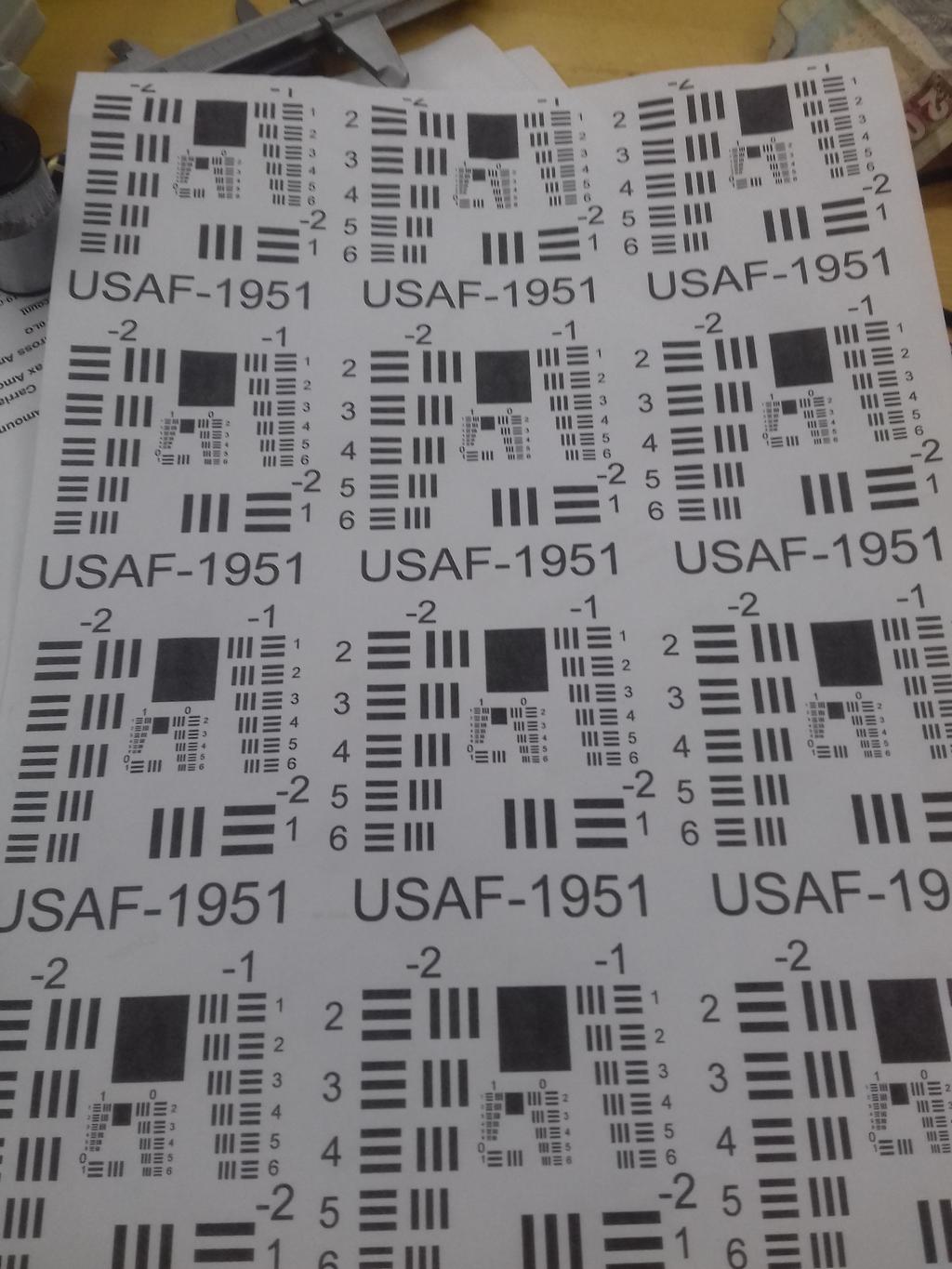
By putting the two lenses together I managed to get some good images which I tested using the cell phone's camera.
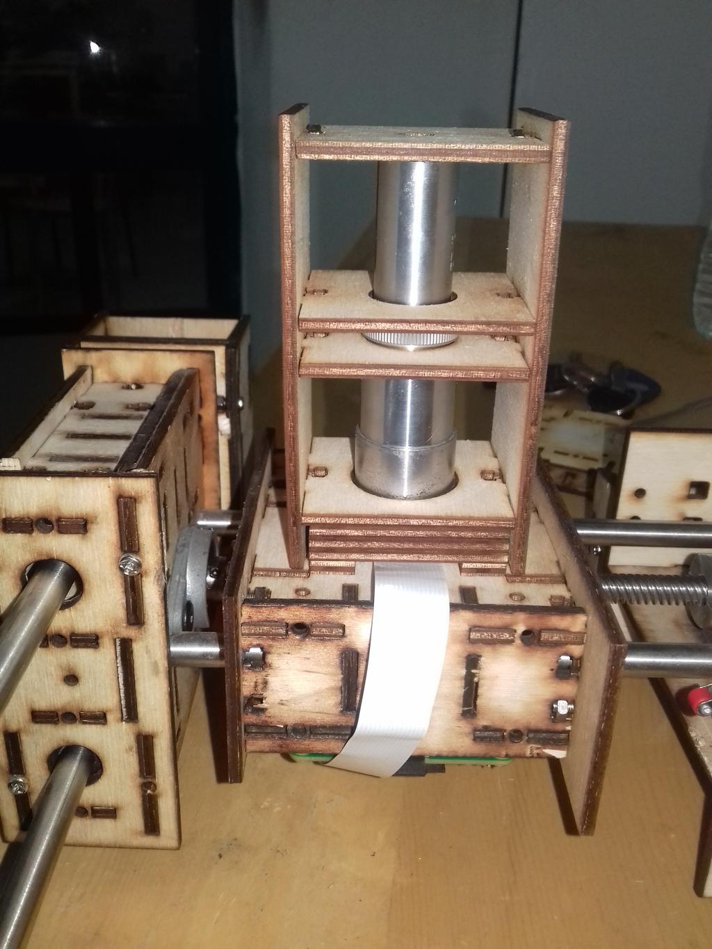
Then back to inventor I designed a lenses holder to place the lenses on top of the camera and on a common axis with the camera's lens. I also redesigned the base plate to accommodate it.
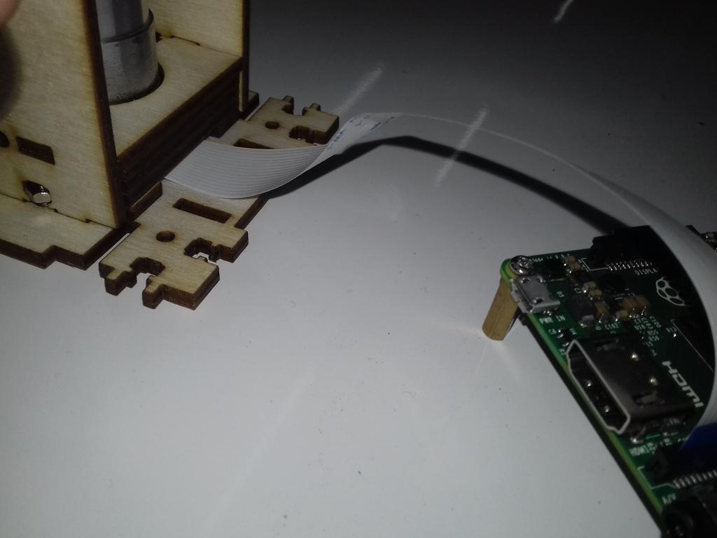
I then installed RPi-Cam-Web-Interfaceto test the camera.
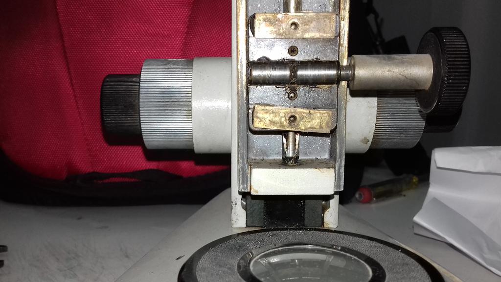
Back to the PZO microscope, I uncovered the piece that adjusts the distance between the stage and the objective lens to understand the mechanism.
At first I thought it was rack and pinion but when I uncovered it I found out that the handle is in direct contact perpendicularly on the shaft of the stage and the friction is tuned by a thin aluminum plate (removed in the photo).
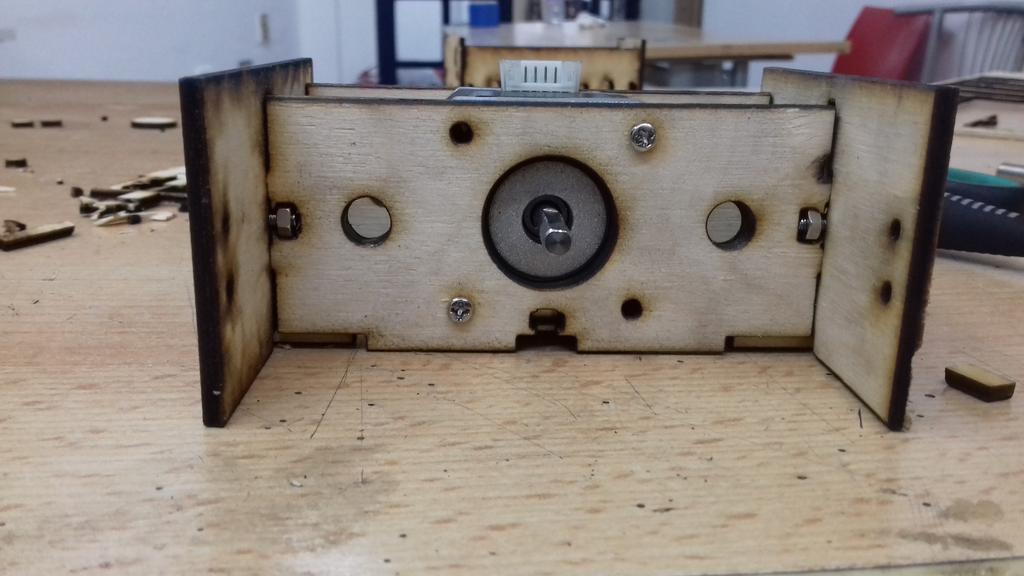
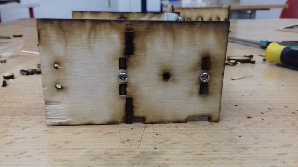
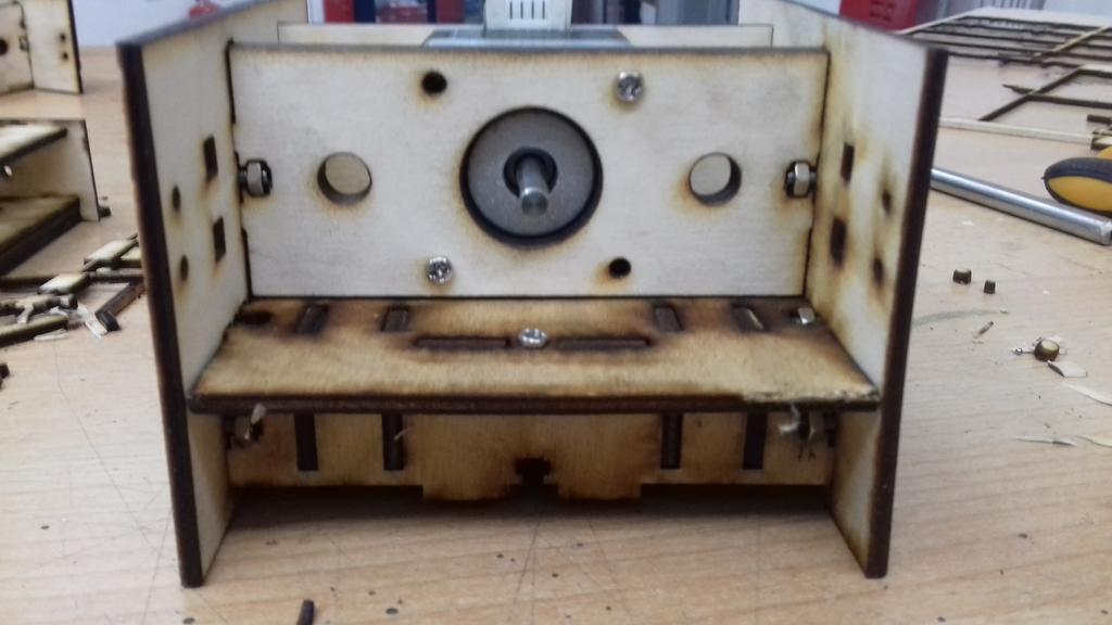
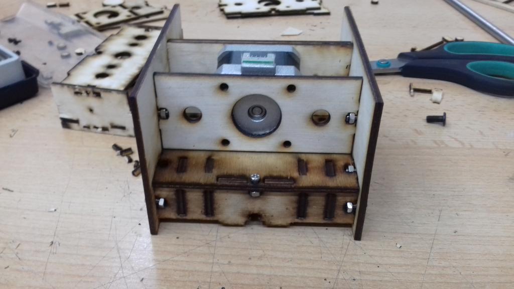
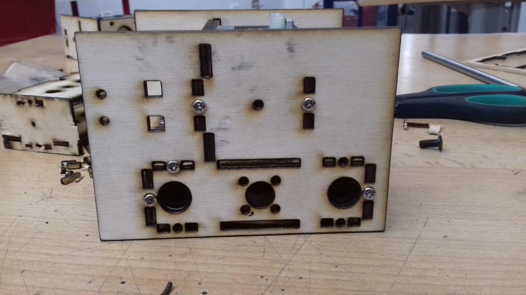
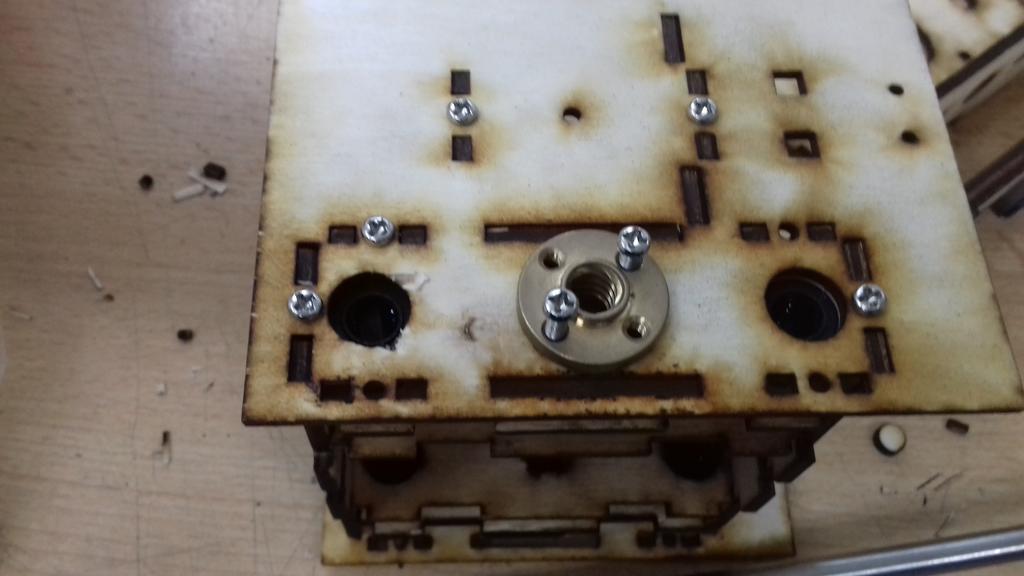
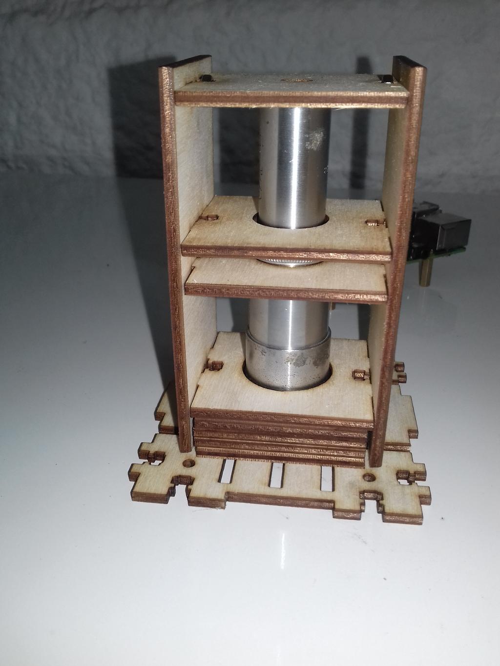
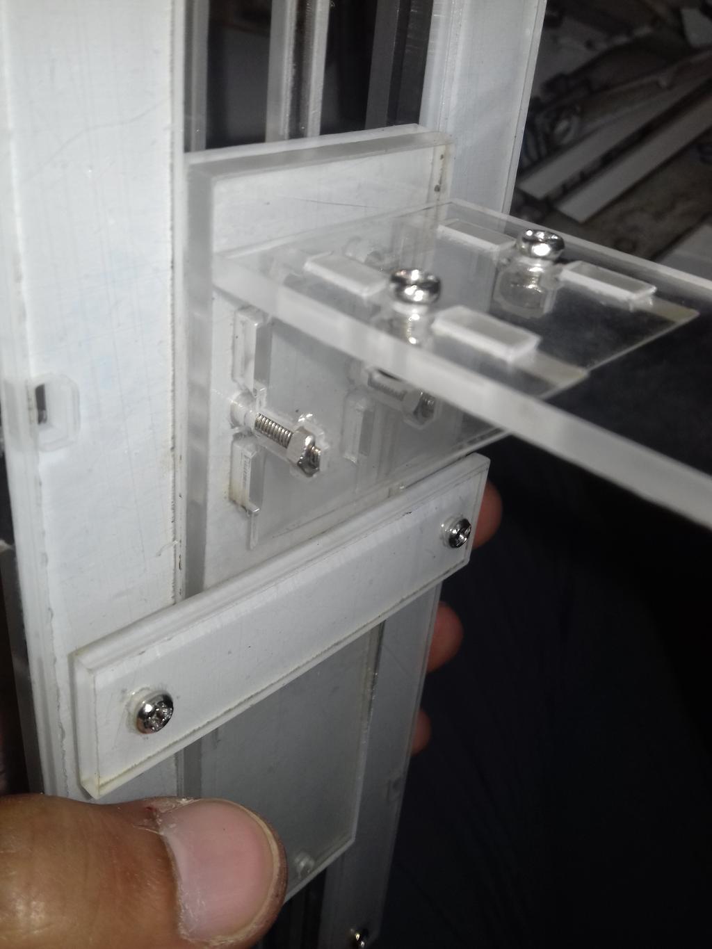
So, I went to test this mechanism so I designed a small test set
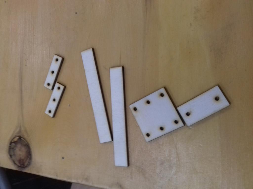
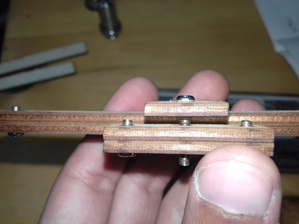
So when I loosen the two screws on the from plate the stage should move freely.
And when I tighten them it was very difficult to move.
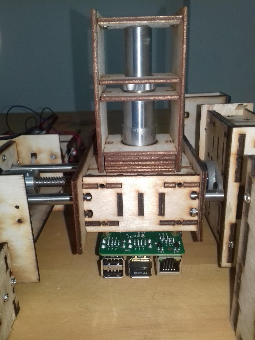
So guided by this mechanism, I designed the stage out of transparent acrylic. the slide stage was joined at a 90 degree angle with the slider with two screws to adjust the tightness.
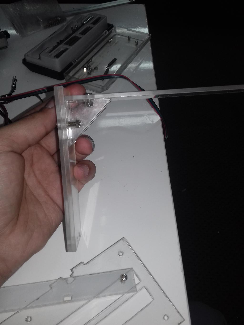
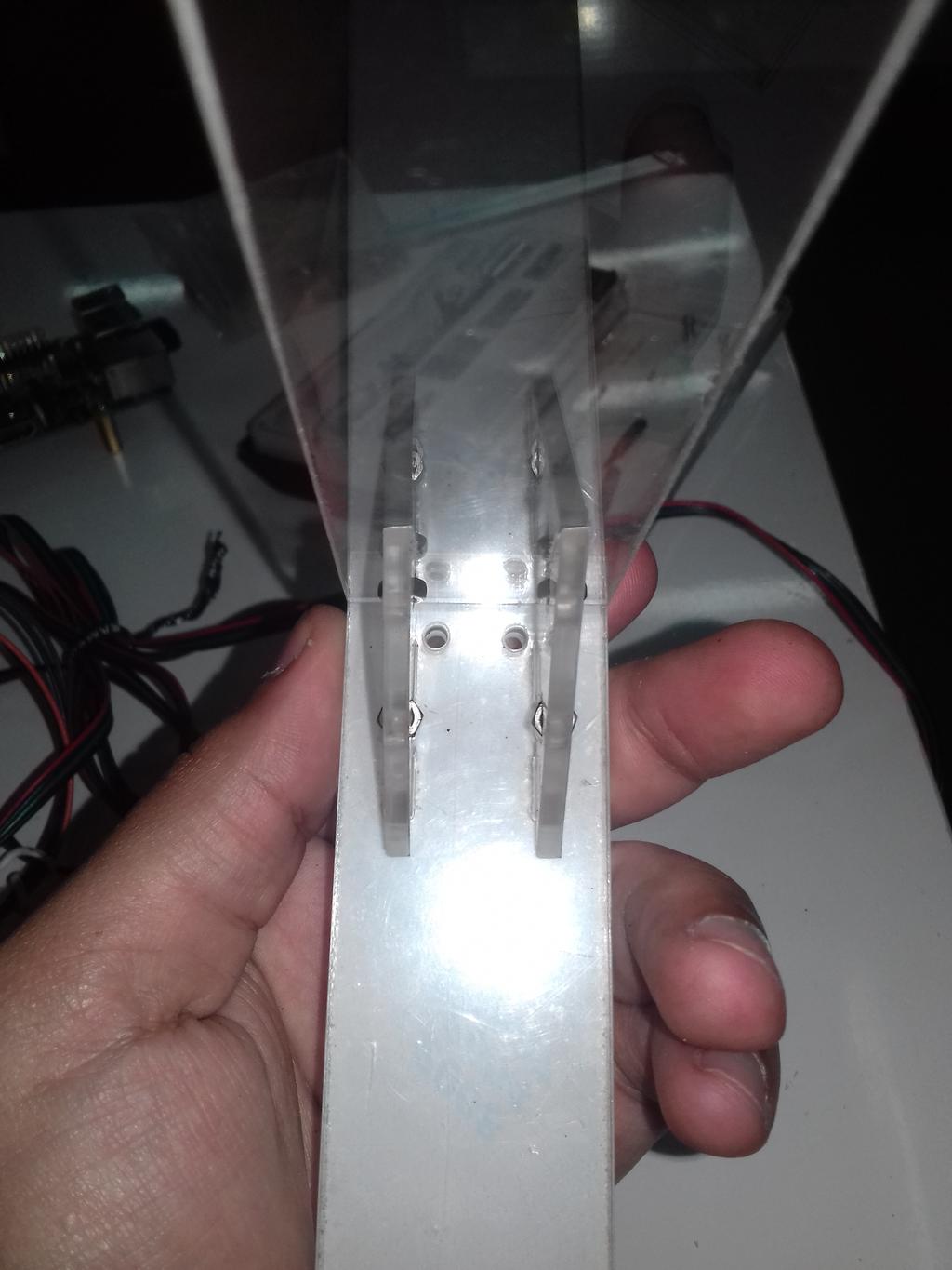
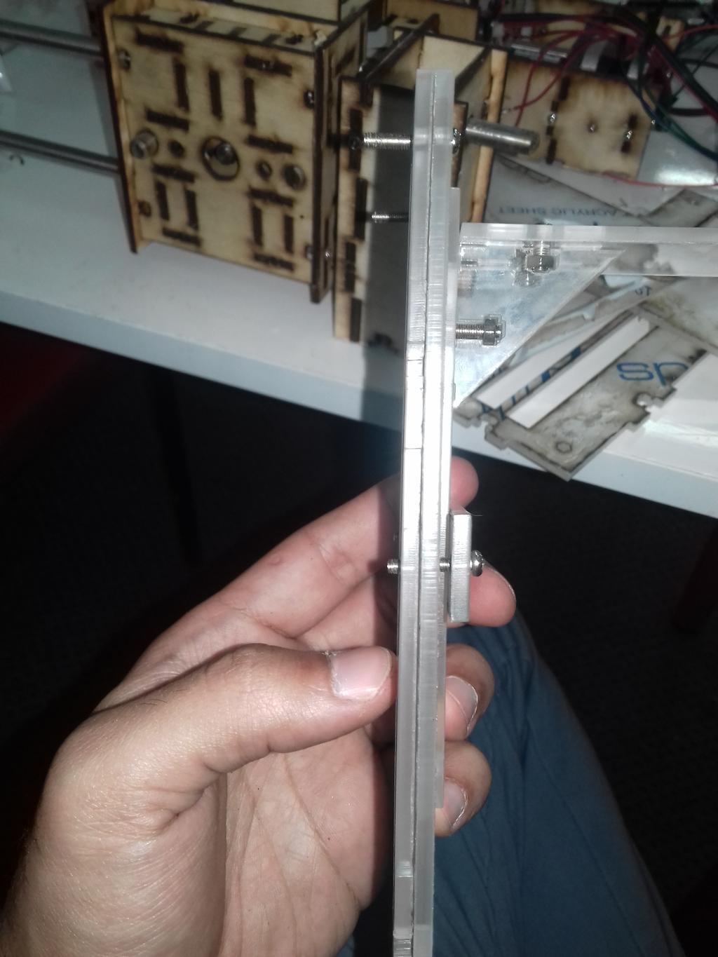
The slide should be placed as such:
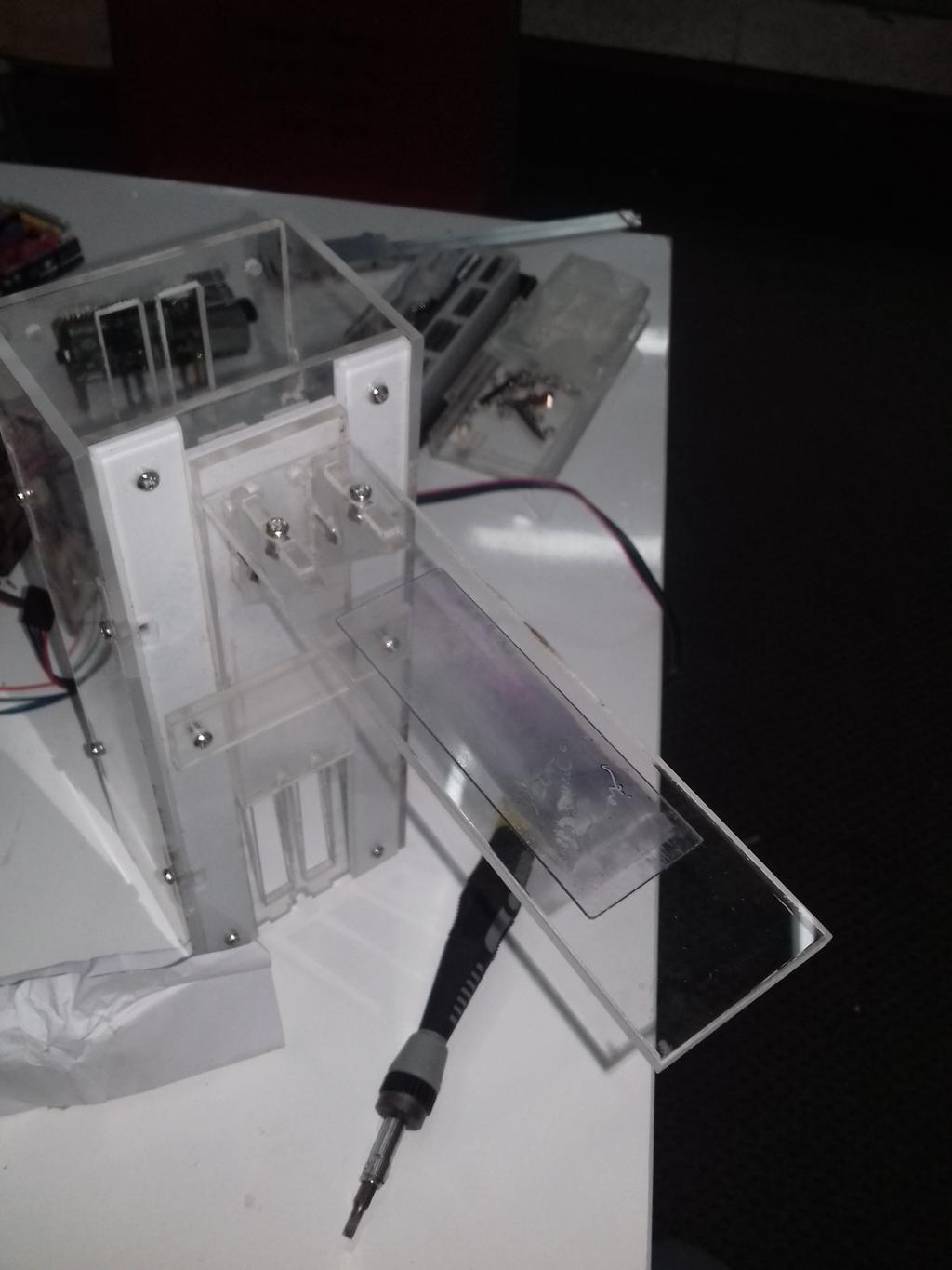
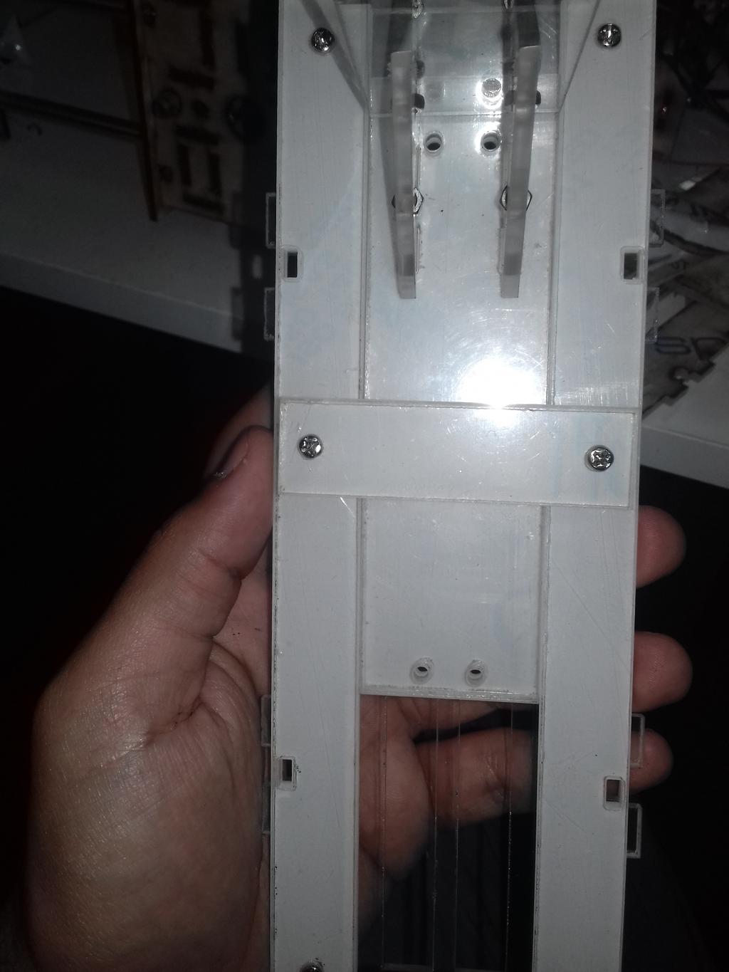
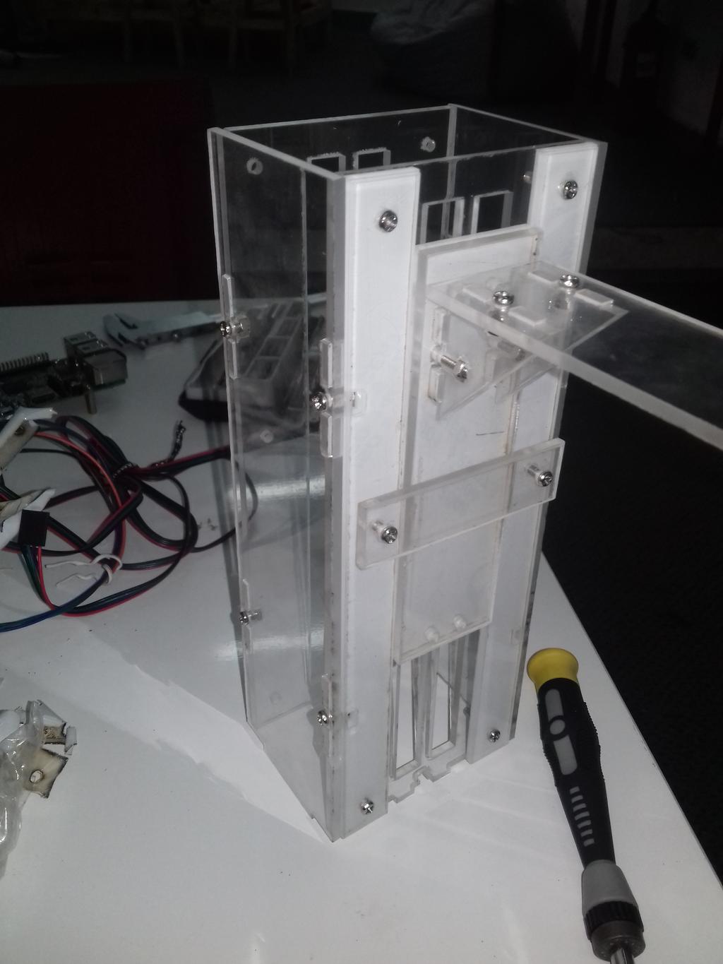
I then edited the design of the base to accommodate the slide holder and the Ardino then cut it. I tried to align the slide holder as best as I could but It didn't went as I designed but it was okay.
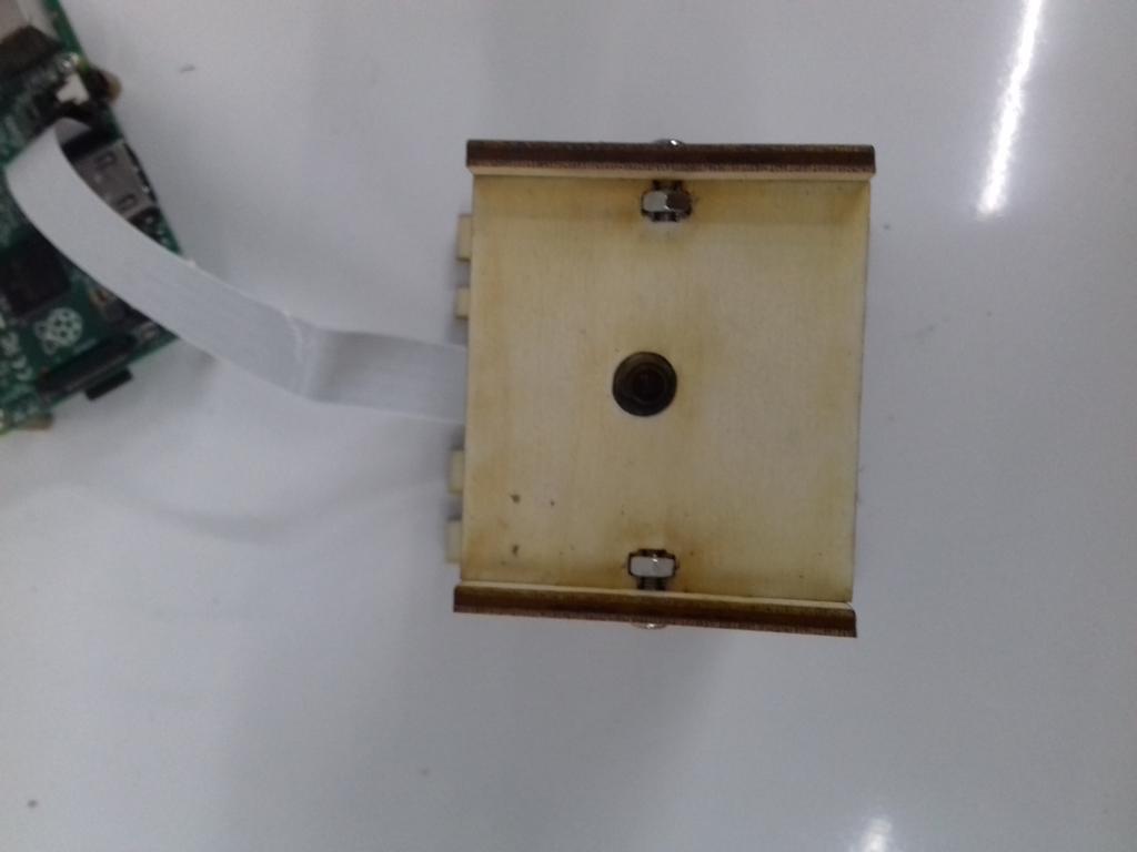
I then fixed the Raspberry Pi at the bottom with 4 spacers and M3 screws.
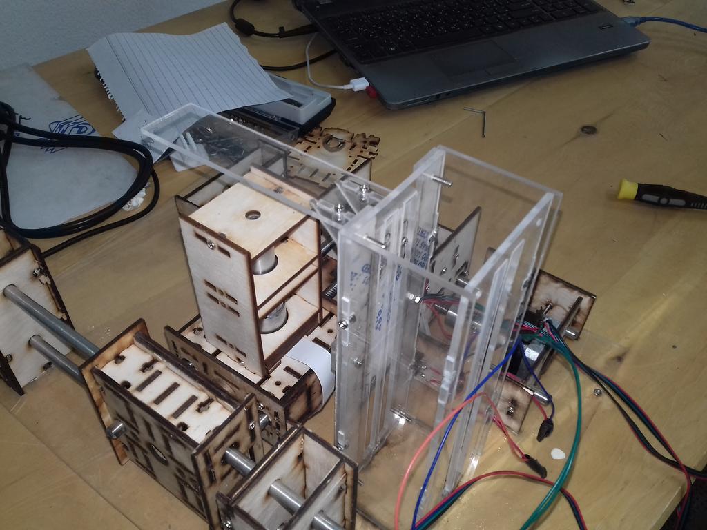
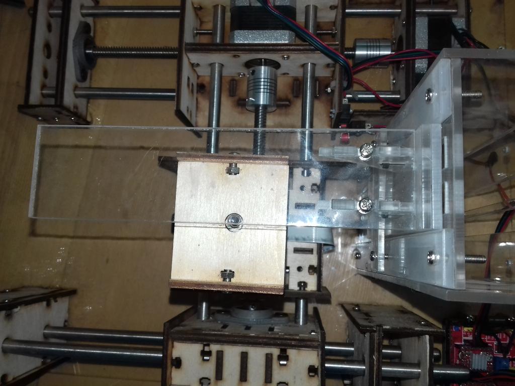
I then started to test the movement
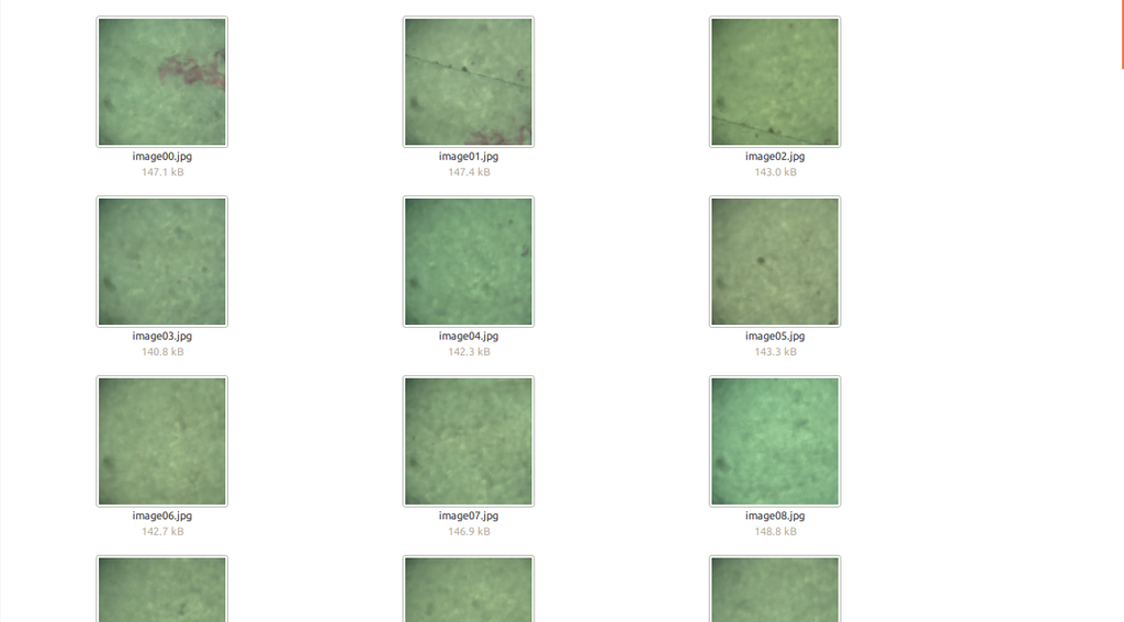
I then made python script that controls the Arduino and the camera module which sends g-codes to GRBL to move it into stops in a snake-like pattern and at every stop executes "raspistill" command to capture the photos. Then it crops the central portion of the image to eliminate optical apparition and create "tiles" to be stitched.
import datetime
import os
import serial
import time
import spur
import shutil
import threading
import logging
import sys
from wand.image import Image
# from wand.display import display

port = '/dev/ttyACM0'
baudrate = 115200

hostname = 'faboscope'
username = 'pi'
password = 'raspberry'

grid_x_count = 10
grid_y_count = 10


def read_from_port():
   while True:
       reading = ser.readline().decode()
       logging.info(ser.name + " >> " + reading)
       print(ser.name + " >> " + reading + "\n")


def ser_write(string):
   ser.reset_input_buffer()
   ser.write(string)
   logging.info(ser.name + ' << ' + string)
   print(ser.name + ' << ' + string + "\n")

with serial.Serial(port, baudrate) as ser, spur.SshShell(hostname=hostname, username=username, password=password, missing_host_key=spur.ssh.MissingHostKey.accept) as shell:
   # Start a new thread for reading serial output
   # serial_thread = threading.Thread(target=read_from_port)
   # serial_thread.start()

   # Initializing GRBL
   ser_write("\r\n\r\n")  # Wake up grbl
   time.sleep(2)  # Wait for GRBL to initialize

   ser_write("$H\n")  # Start homing cycle

   # Start images capturing sequence

   direction = 0.1  # The direction
   y_step = 0.1  # Y step value

   timestamp = datetime.datetime.utcnow().strftime("%Y-%m-%d_%H-%M-%S")
   images_dir = "images/" + timestamp + "_" + str(grid_x_count) + "-" + str(grid_y_count)
   original_path = images_dir + "/original"
   cropped_path = images_dir + "/cropped"

   if os.path.exists(images_dir):
       shutil.rmtree(images_dir)
   os.mkdir(images_dir)
   os.mkdir(original_path)
   os.mkdir(cropped_path)
   i = 0  # Images counter
   result = shell.run(["rm", "-rf", "faboscope_images"])
   logging.info(username + "@" + hostname + " > " + result.output)
   result = shell.run(["mkdir", "faboscope_images"])
   logging.info(username + "@" + hostname + " > " + result.output)

   # Row by row
   for row in range(0, grid_y_count):
       # Column by column
       for column in range(0, grid_x_count):

           filename = "image%02d" % i + ".jpg"

           result = shell.run(["raspistill", "-n", "-vf", "-hf", "-o", "faboscope_images/" + filename])
           logging.info(username + "@" + hostname + " > " + result.output)
           with shell.open("faboscope_images/" + filename, "rb") as remote_file:
               local_image_path = original_path + "/" + filename
               with open(local_image_path, "wb") as local_file:
                   shutil.copyfileobj(remote_file, local_file)

                   with Image(filename=local_image_path) as img:
                       width = img.size[0]
                       height = img.size[1]
                       x = (width / 2) - 250
                       y = (height / 2) - 250
                       img.crop(x, y, width=500, height=500)
                       img.save(filename=cropped_path + "/" + filename)
                       i += 1
           if column < grid_x_count - 1:
               ser_write("G21 G91 G0  X" + str(direction) + "\n")

       if row < grid_y_count - 1:
           ser_write("G21 G91 G0  Y" + str(y_step) + "\n")
           direction *= -1  # Invert the direction for a snake-like pattern
   ser.close()
Original photos
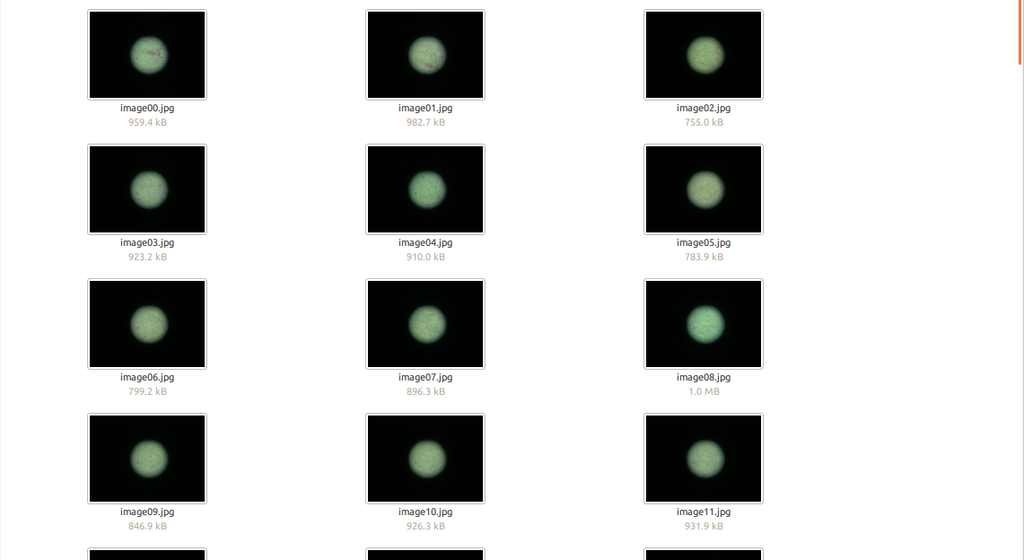
Cropped photos
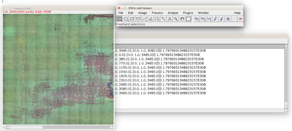
So the next image is to stitch the created tiles using Fiji
The problem was that the raspberry pi has limited resources and Fiji's launcher wasn't compiled for ARM processors so I tried on the PC first using Fiji GUI.
By Choosing Plugins > Stitching > Grid/Collection stitching, A window will appear displaying available methods of stitching.
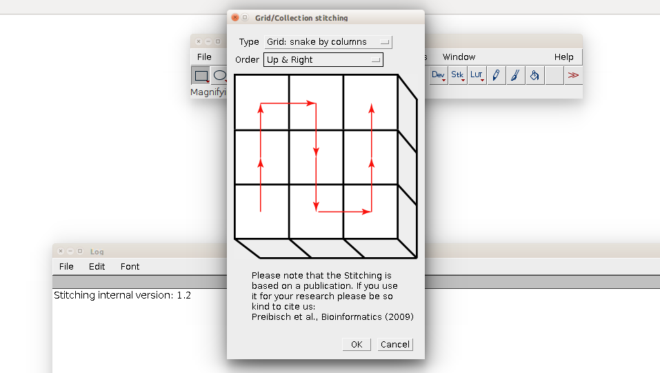
I chose "Grid: snake by column" and "Up & right"
By hitting OK a bunch of settings is displayed
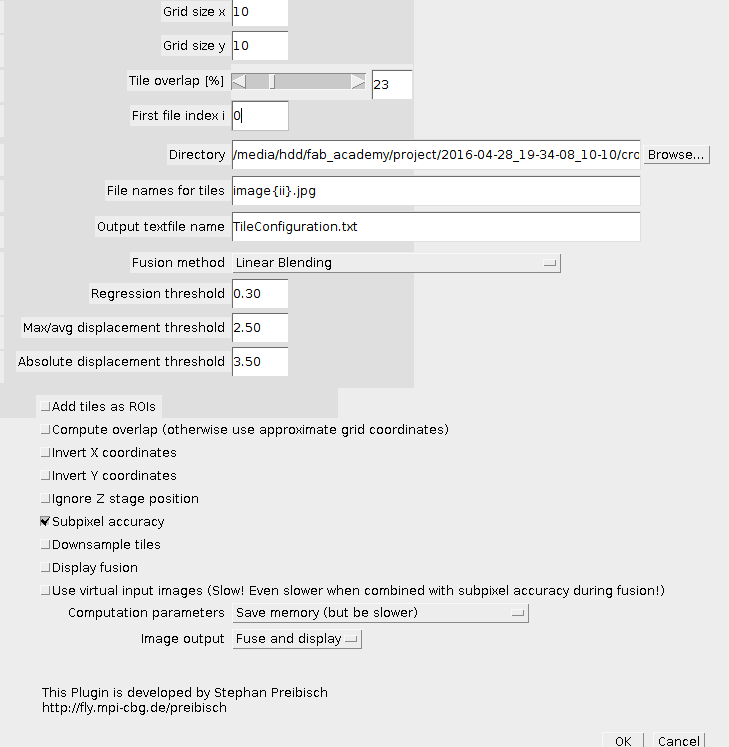
- Grid Size:is the number of tiles that are available in x an y. in my case it was 10
- Tile overlapis the percentage of overlap between the tiles that ImageJ uses as a guide to stitch.
I tried various values and 23was the closest to my settings. - First file index i:Is the starting number of the images sequence.
- File names for tiles:is the file-naming scheme used to name the tiles "i" is replaces with the index for the tile.
- Compute overlap:when checked it leaves the overlap setting to ImageJ to calculate but found this to produce unexpected results so I unchecked it.
Then I it ok and the stitching process began
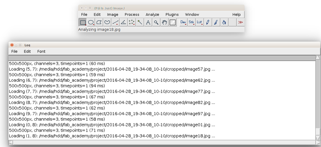
And then the result appears which you can save by choosing File>Save
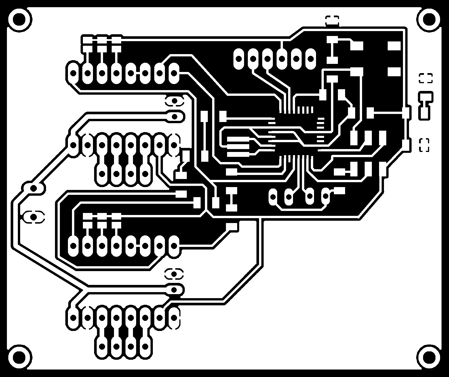
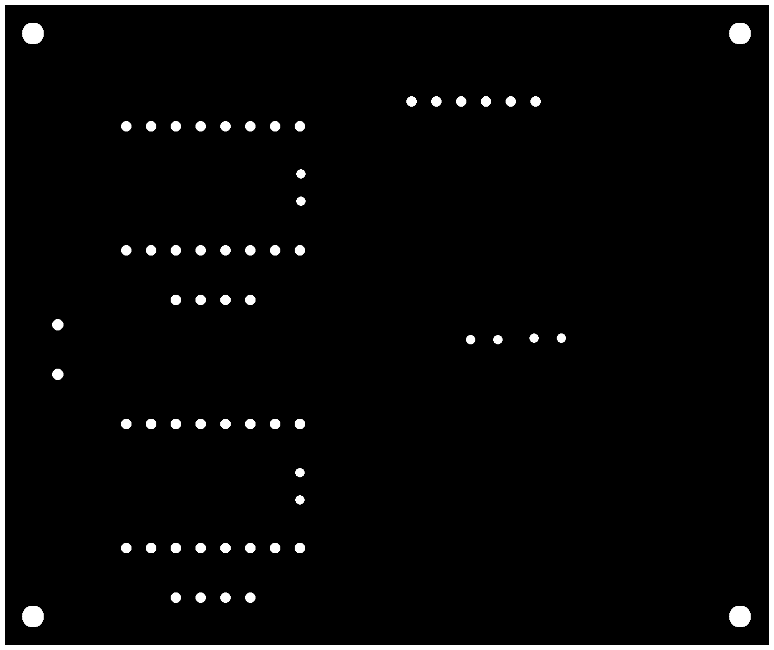
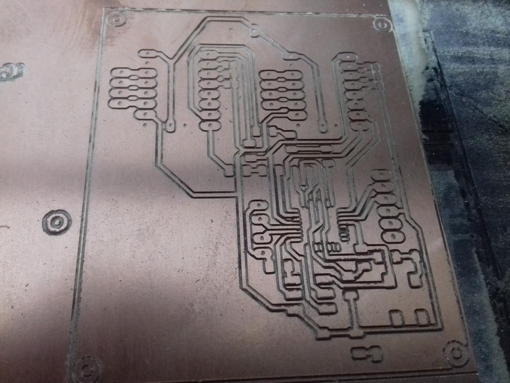
Circuit Design and Production
I used Arduino flashed with GRBL shield to interpret G-Code I sent serially through USB from the Raspberry Pi and GRBL shield to handle the motor drivers, limit switches and hardware settings.
http://blog.protoneer.co.nz/arduino-cnc-shield/
At the time of writing this documentation, the developer didn't share source files for the circuits and decided to not publish future versions of the design files.
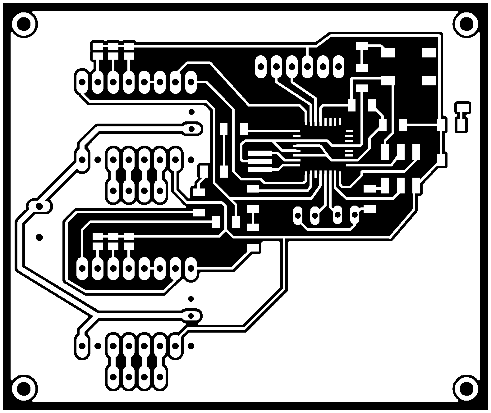
But in the photo gallery he posted the circuit schematic design photo so I used this to try and create my own circuit in Eagle.
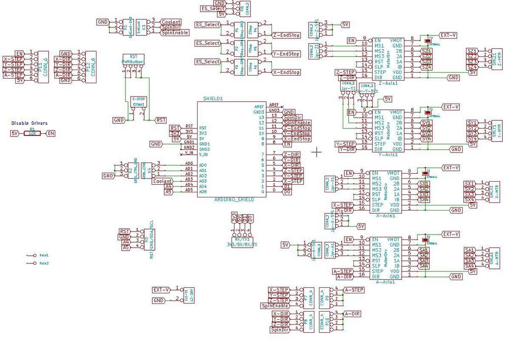
The board mainly consists of:
- ATMEGA328P: To replace the Arduino.
- Pin headers for Pololu A4988 Stepper Drivers: for X and Y movements.
- Solder Jumper Joints: To configure micro-stepping.
- Power Terminals : for 12V supply to the motors.
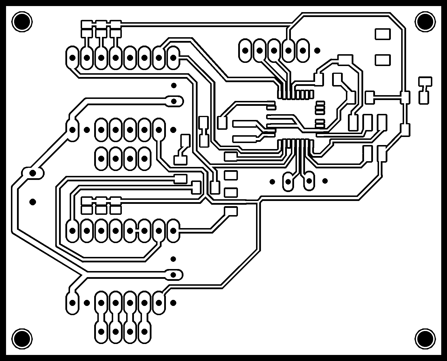

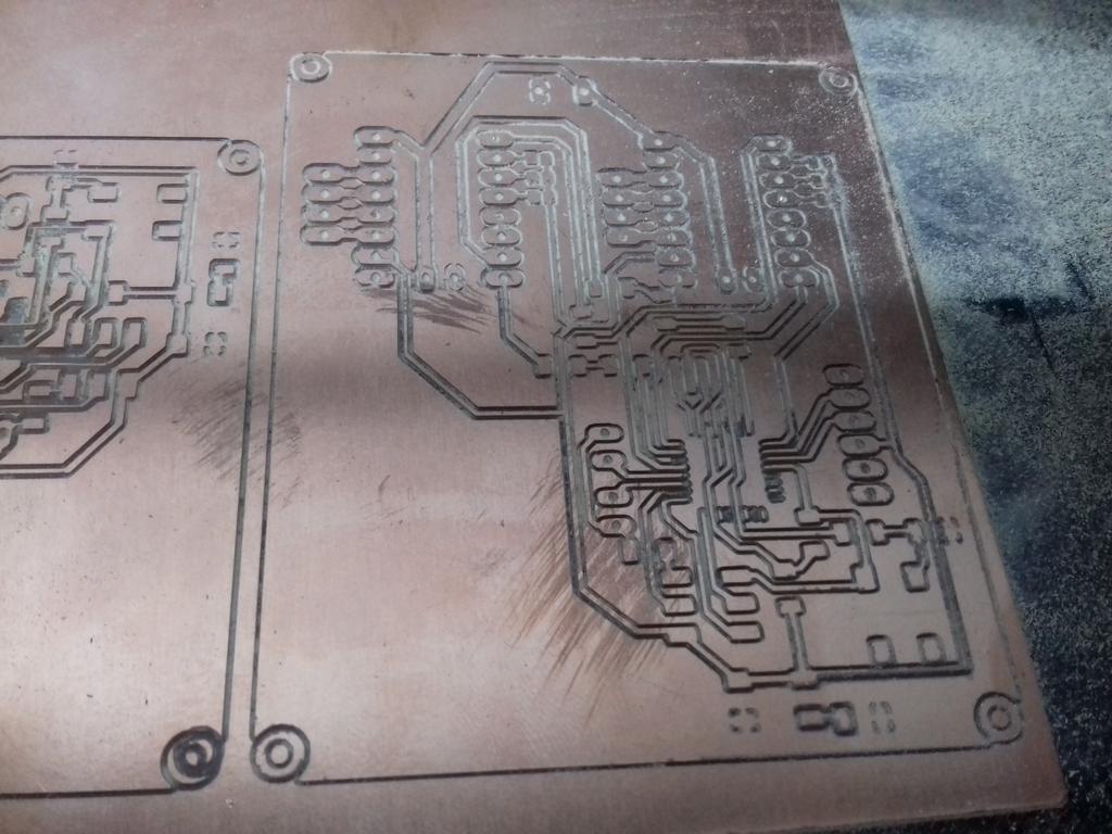
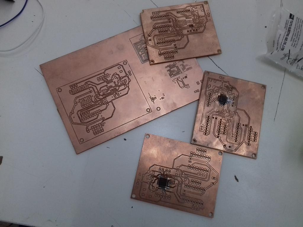
The milling for this version for successful but when I tried to solder the ATMEGA there were shorts, I believe this happened because I didn't add much Isolation for the ground plate and this made it difficult to solder the ATMEGA without creating short.
I increased isolation and added thermals for other components,
But as I tried to adjust the diameter in Milling this led to destroying the ATMEGA traces.
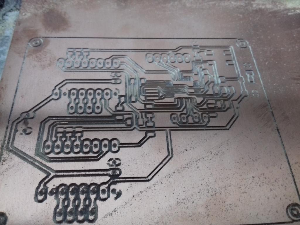
I played with the milling parameters a little but the result was that all the not-connected pins pads were destroyed and the two traces for the limit switched were also destroyed. I tried to create a solder jumper to the ATMEGA pins but the space were big.
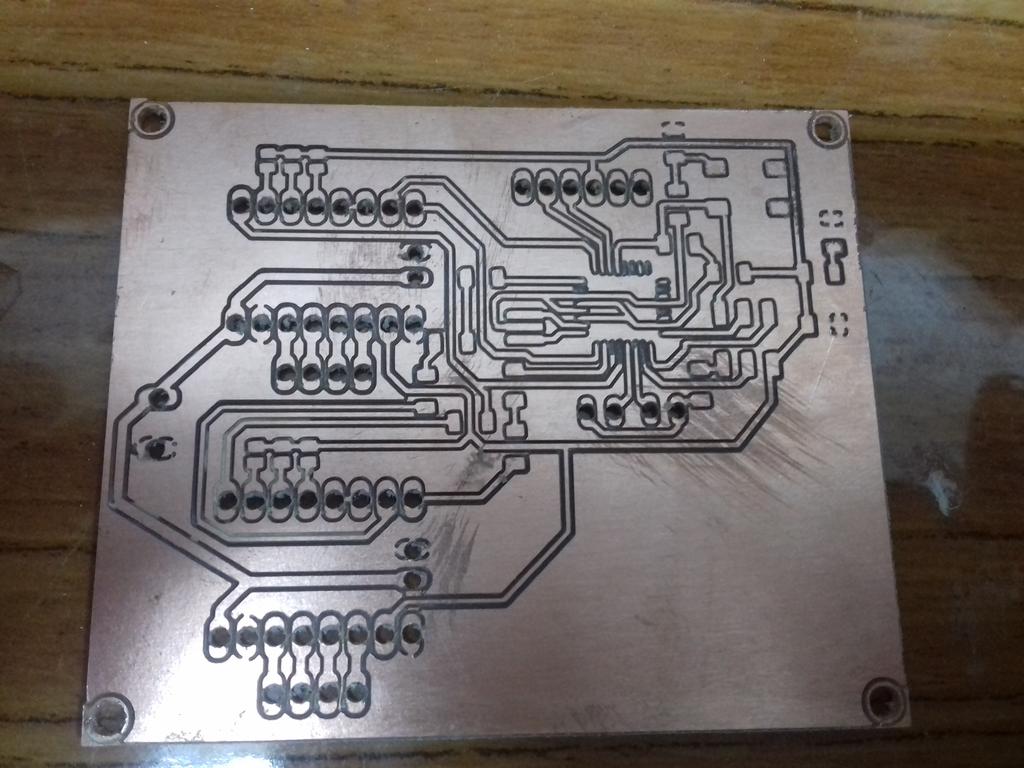
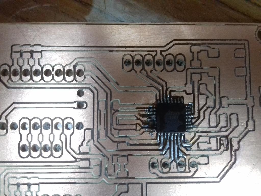
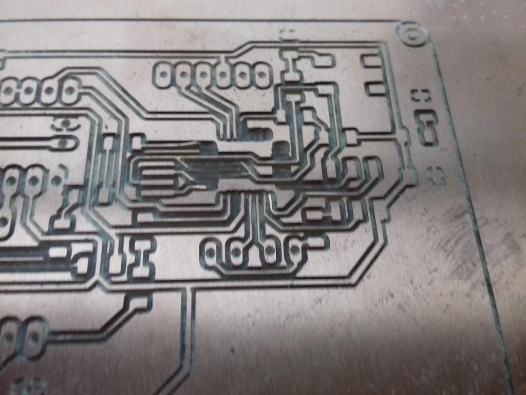
I modified the board a little and removed the thermals so that I can focus on the ATMEGA and the results were quite satisfactory.

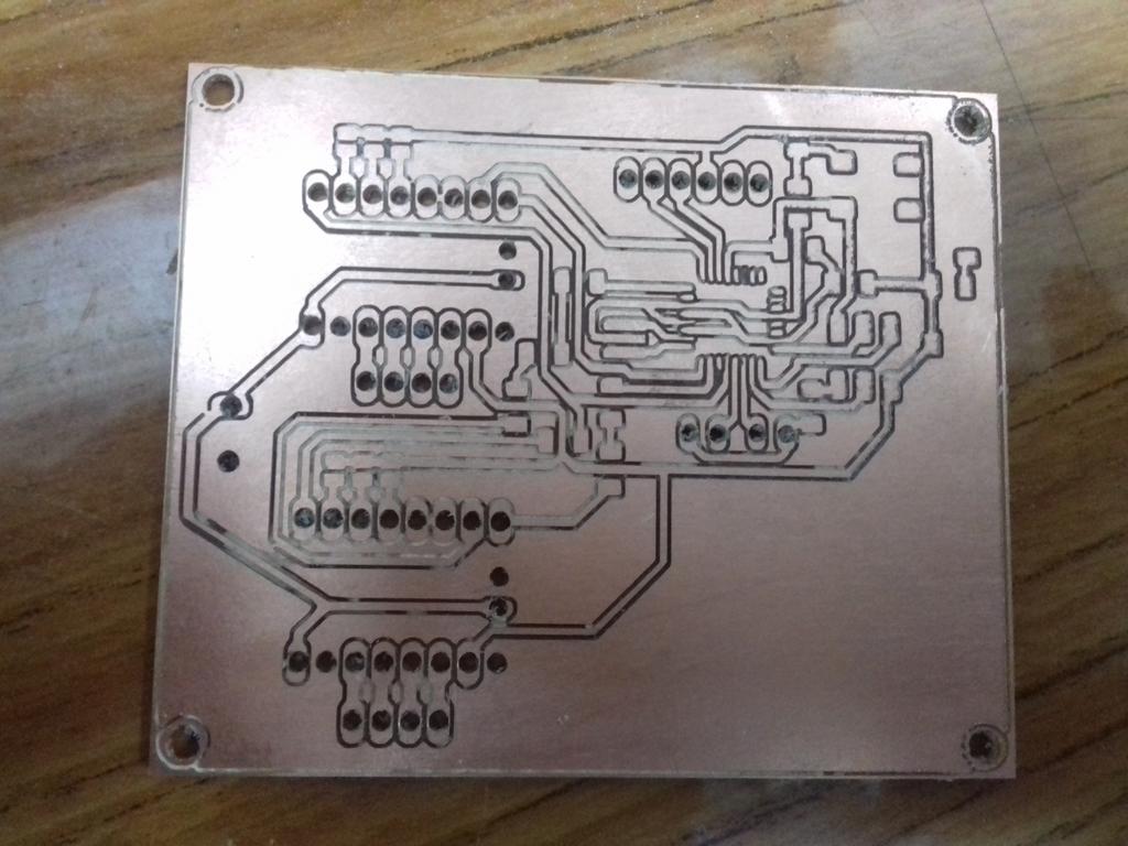
Apart from some incomplete milling of the traces (probably because I modified the 'error' parameter to create straight lines), the board was good.
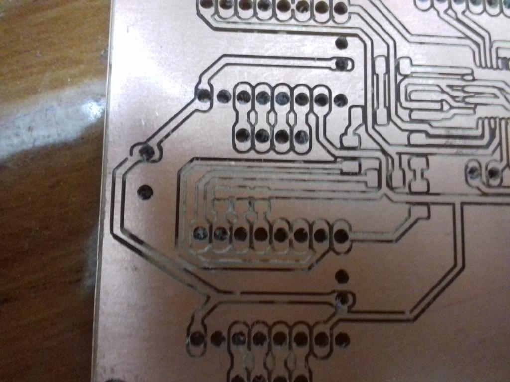
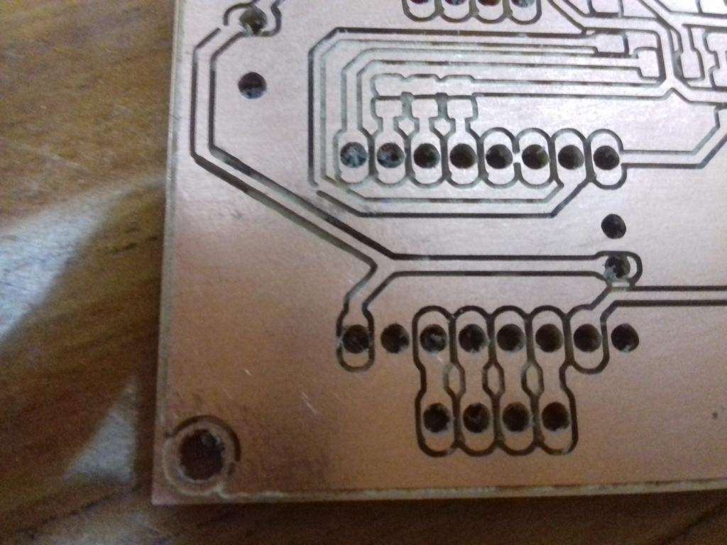
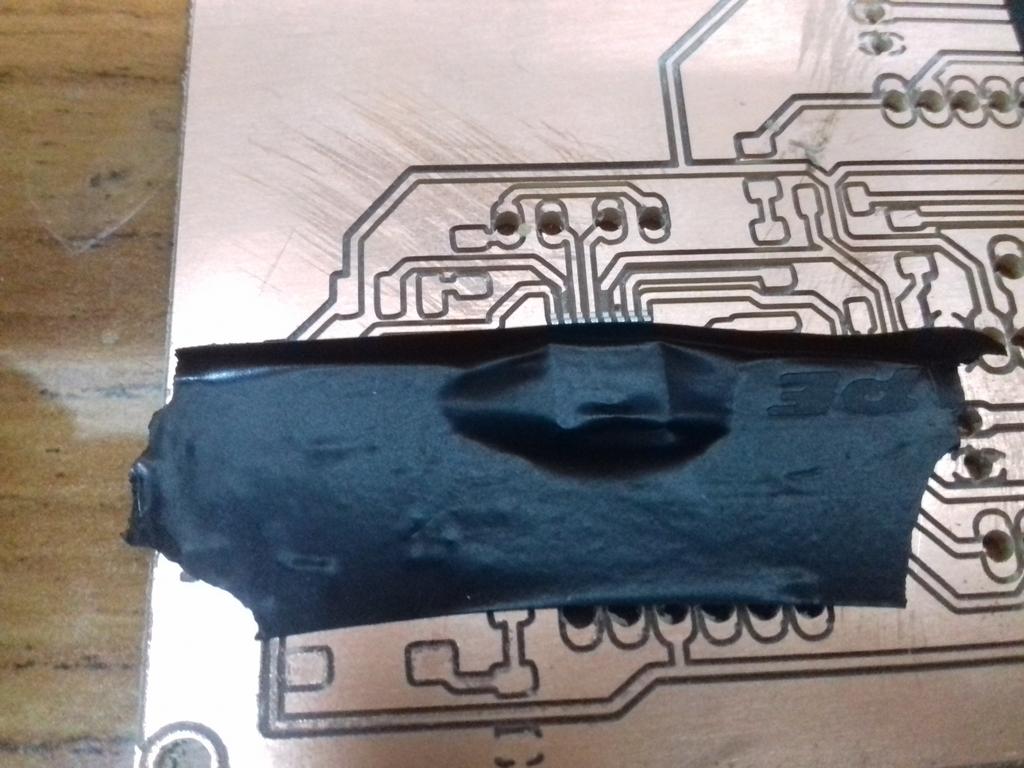
The I tried to solder the ATMEGA again but one of the pins was bent underneath it and as I attempted to correct this I destroyed the crystal trace
All that is left is a trail of failed boards and broken end-mills :)
Bill of Materials
- 3mm Plywood sheets
- M3x8mm screws
- M3x16mm screws
- 2x NEMA-17 Stepper Motors
- FabGRBL Board (Single Side FR-1 Copper)
- 11x Linear Bearings
- 8mm Aluminum Shafts
- 8mm Lead Screw
- 2x Flanged Radial Bearing
What's next
- There are problems with running ImageJ on Raspberry Pi 2 B+; The limited RAM prevents ImageJ from stitching also Fiji launcher isn't compiled for ARM processors. Now I'm trying to get ImageJ to run in a headless mode to process a macro that automate the stitching and increase the memory limit
- Create a web interface for the device.
- Modify the design so that It can produced as a kit.