Input Devices
For this assignment I thought about the touchpad projects mentioned in the schedule and they made me remember a project I've seen before called Luxaforand thought to myself, This is a good project to learn about input, output, interfacing and networking so this will span along those assignments.
The Idea
The idea here is to create a touchpad board which is used to control a RGB LED and later on being able to control it from a computer then make a two boards that switch each other.
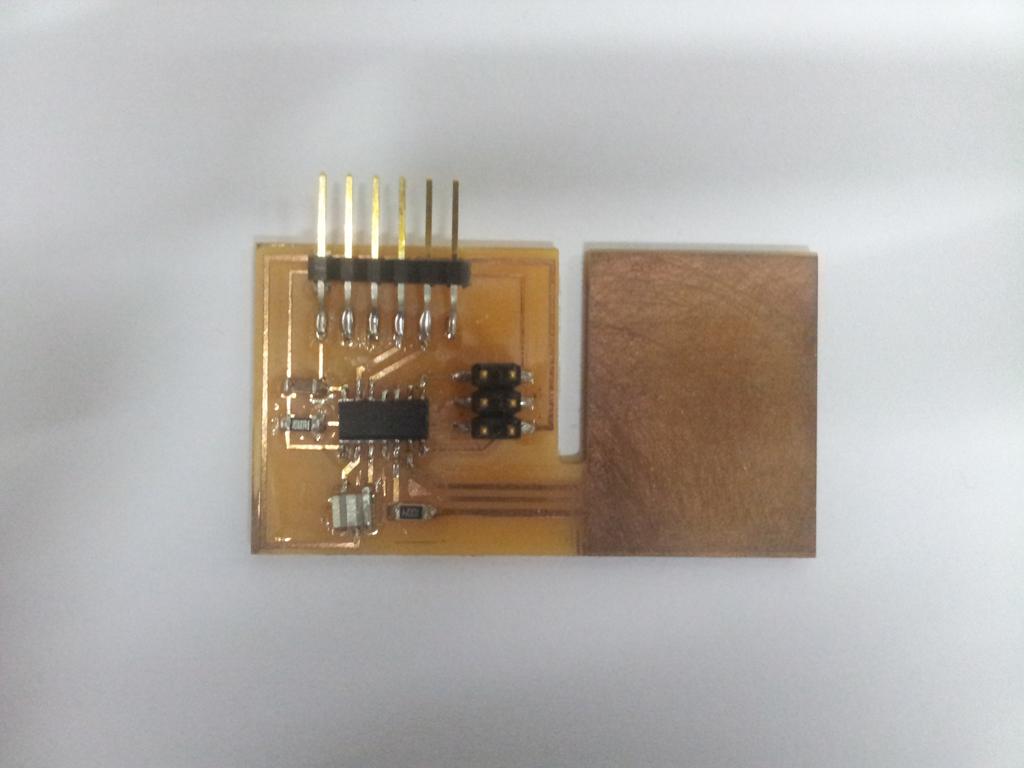
The Board
For this assignment the board's function will be to detect touch and activate the RGB LED board that will be designed in the next assignment through the ISP cable.
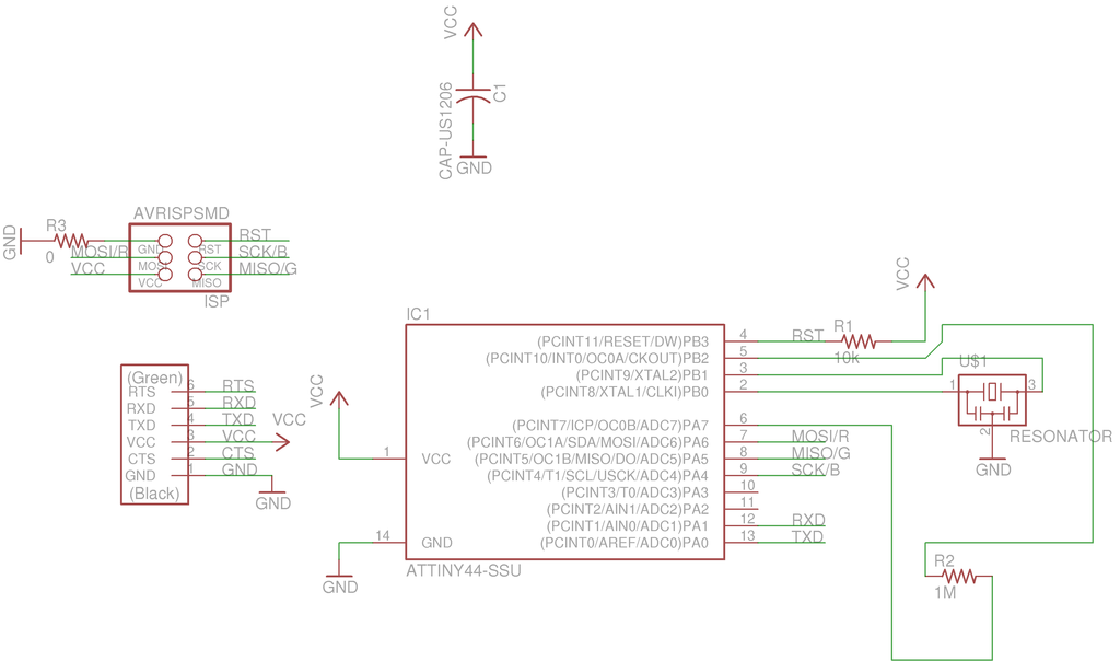
These are the pins that will be used:
- Pin 6 (Arduino 8) Charge Pin:used to send current to the pad and the 1 Mega Ohm resistor
- Pin 5 (Arduino 7) Sense Pin:used to recieve the current which is used to detect touch.
- Pin 7 (Arduino 6) Red LED:also used for MOSI
- Pin 8 (Arduino 5) Green LED:also used for MISO
- Pin 9 (Arduino 4) Blue LED:also used for SCK
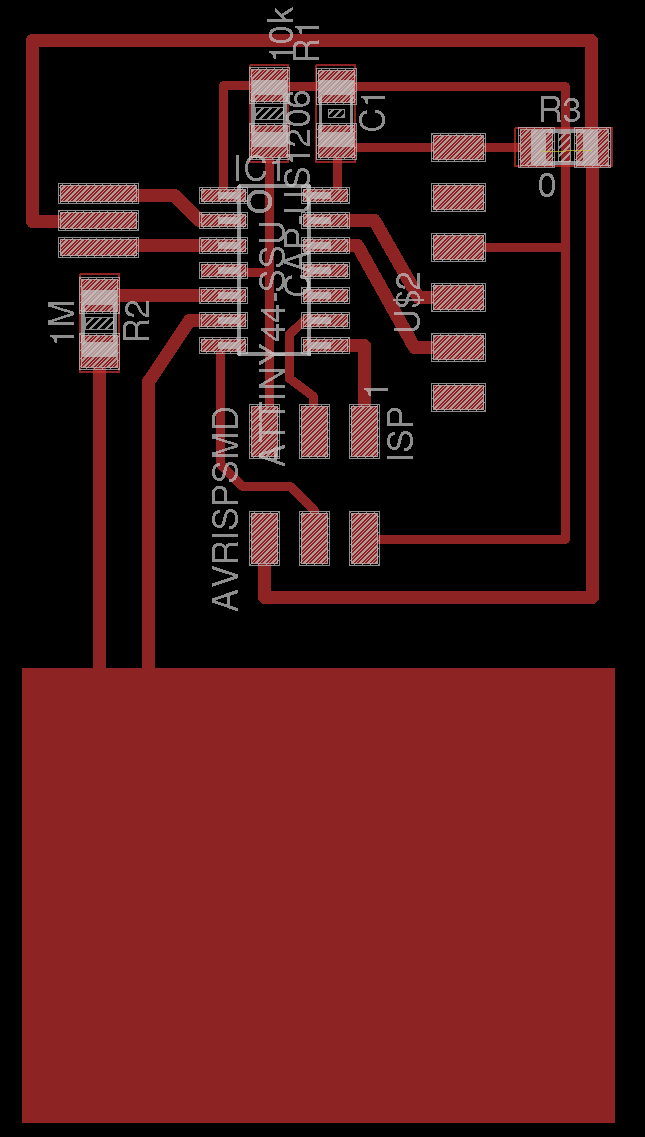
Traces and Interior
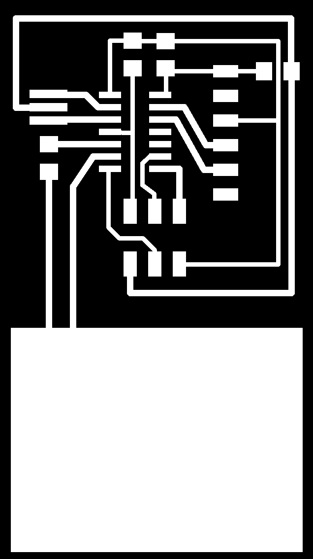

The Final Board
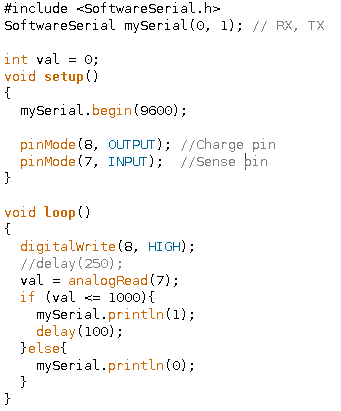
Programming
First I uploaded a test Arduino sketch to use serial communication to see what the threshold value was.
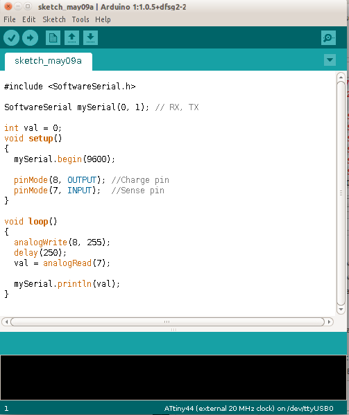
I found that the threshold value is below 1000, so I rewrote the sketch to signal on and off statuses.