#08week
embedded programming
tasks- - read the datasheet (ATTiny44)
- - write a program that does something
This week assignment was to make use of a programming language - in our case 'C'.
In order to programm a microprocessor like the ATTiny we have to know about the internal structure of itself. Therfore it is a must to read the specific datasheet of the components to know how to access the individual functions of it.
The hardware I used was the board I made during my electronics design week - it works fine and it is logical to go on with this instead making a new one especially when time is short. And in my case it's more then short because i'm a totally novice regarding programming, but i'll give my best.
To understand the basics of programming I reviewed different sources and books to get some clues about it.
I decided not to go with the terminal for compiling and uploading the programm instead I used the Arduino IDE that I'm, at the moment, more comfortable with. This way, it was necessary to understand the ATTiny's Pin-Outs based on Arduino's configuration but I used a similar workflow before for the fabISP and the second board too.
As I have used the Arduino IDE already with my boards all neccessary libraries were already installed - so I could skip that step and went straight to the coding part.
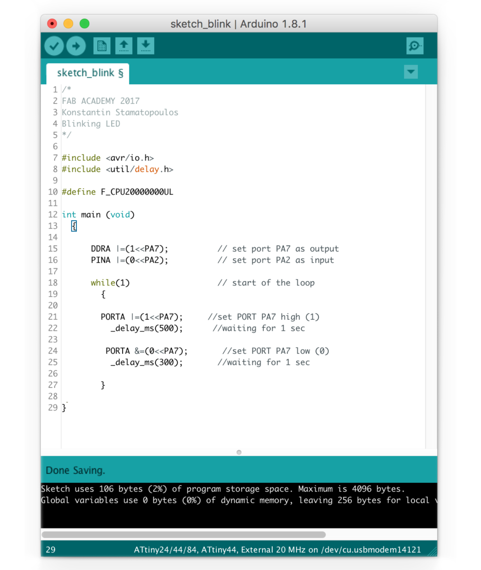
Just to show my settings that has to be set within the Arduino-IDE
Board "ATtiny"
Processor:"ATtint44"
Clock: "20 MHz (external)"
Programmer: "ArduinoISP"
Then I started writing the C programming for the very first time. For this I studied different C-scripts from various sources and compared them. It took a while till I understand the logic - still not everything is clear to me at this moment. At first I downloaded the datasheet for the ATTiny from Atmel. In this 280+ pages containing document everything is documented that has anything to do with the microprocessor. It also contains some example scripts in assembler and in c and some examples for the electronic design. A good source to start with the AVR/C programming is the publication:

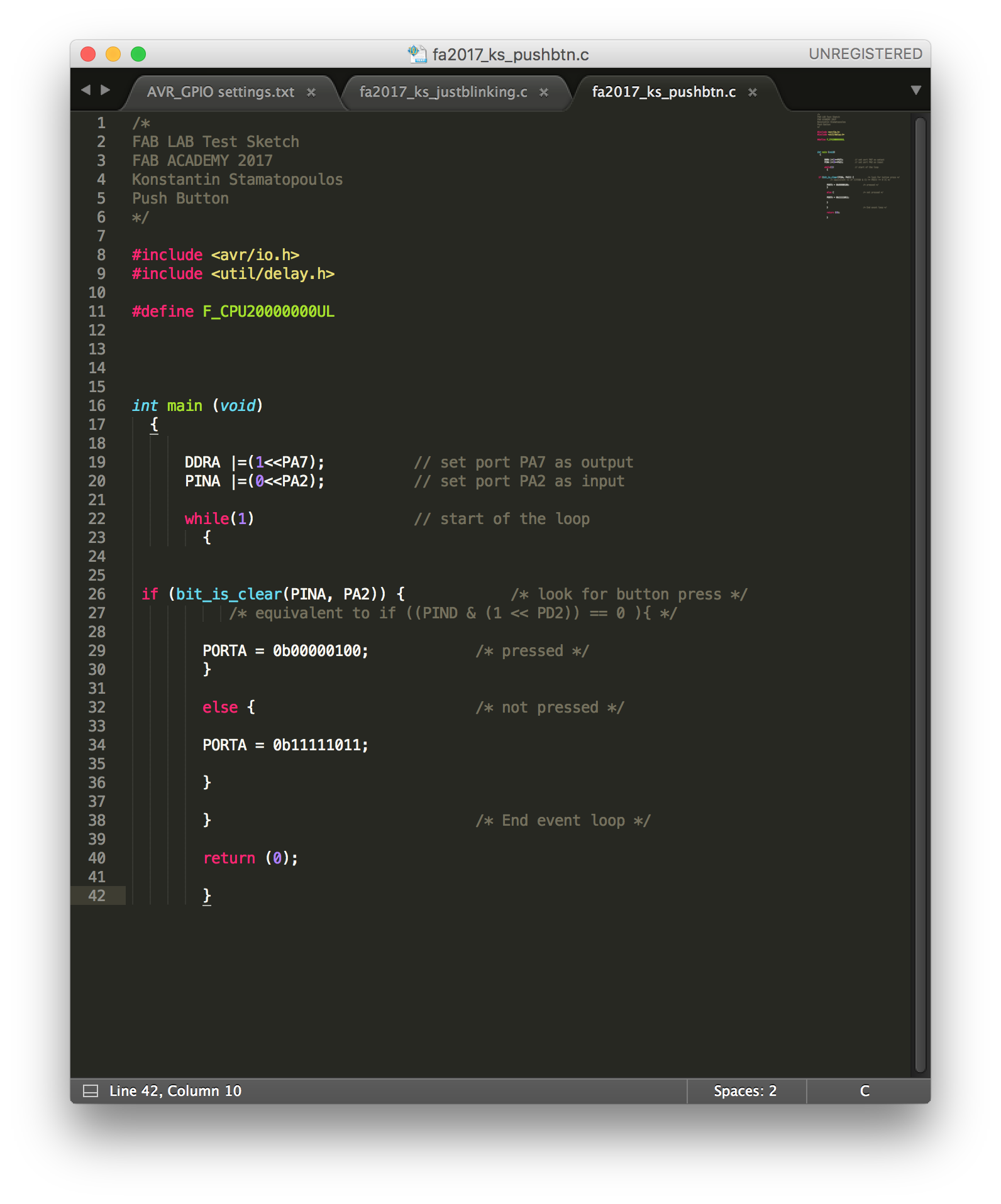
On the second sketch I used a button as an input device - simple to switch on a LED. The first part of the sketch is equal to the first sketch, by assigning in and outputs. The difference starts with the loop, at the beginning the PIN PA2 is sensed if it is pressed or not.
With the following lines each state is assigned - 0b00000100 = high = 1 = pressed and 0b11111011 = low = 0 = not pressed.
The hardware I used was the board I made during my electronics design week - it works fine and it is logical to go on with this instead making a new one especially when time is short. And in my case it's more then short because i'm a totally novice regarding programming, but i'll give my best.
To understand the basics of programming I reviewed different sources and books to get some clues about it.
I decided not to go with the terminal for compiling and uploading the programm instead I used the Arduino IDE that I'm, at the moment, more comfortable with. This way, it was necessary to understand the ATTiny's Pin-Outs based on Arduino's configuration but I used a similar workflow before for the fabISP and the second board too.
As I have used the Arduino IDE already with my boards all neccessary libraries were already installed - so I could skip that step and went straight to the coding part.
Just to show my settings that has to be set within the Arduino-IDE
Board "ATtiny"
Processor:"ATtint44"
Clock: "20 MHz (external)"
Programmer: "ArduinoISP"
Then I started writing the C programming for the very first time. For this I studied different C-scripts from various sources and compared them. It took a while till I understand the logic - still not everything is clear to me at this moment. At first I downloaded the datasheet for the ATTiny from Atmel. In this 280+ pages containing document everything is documented that has anything to do with the microprocessor. It also contains some example scripts in assembler and in c and some examples for the electronic design. A good source to start with the AVR/C programming is the publication:
The book Make: AVR Programming helped me to get a basic understanding, from both the AVR microcontroller and the programming language c.
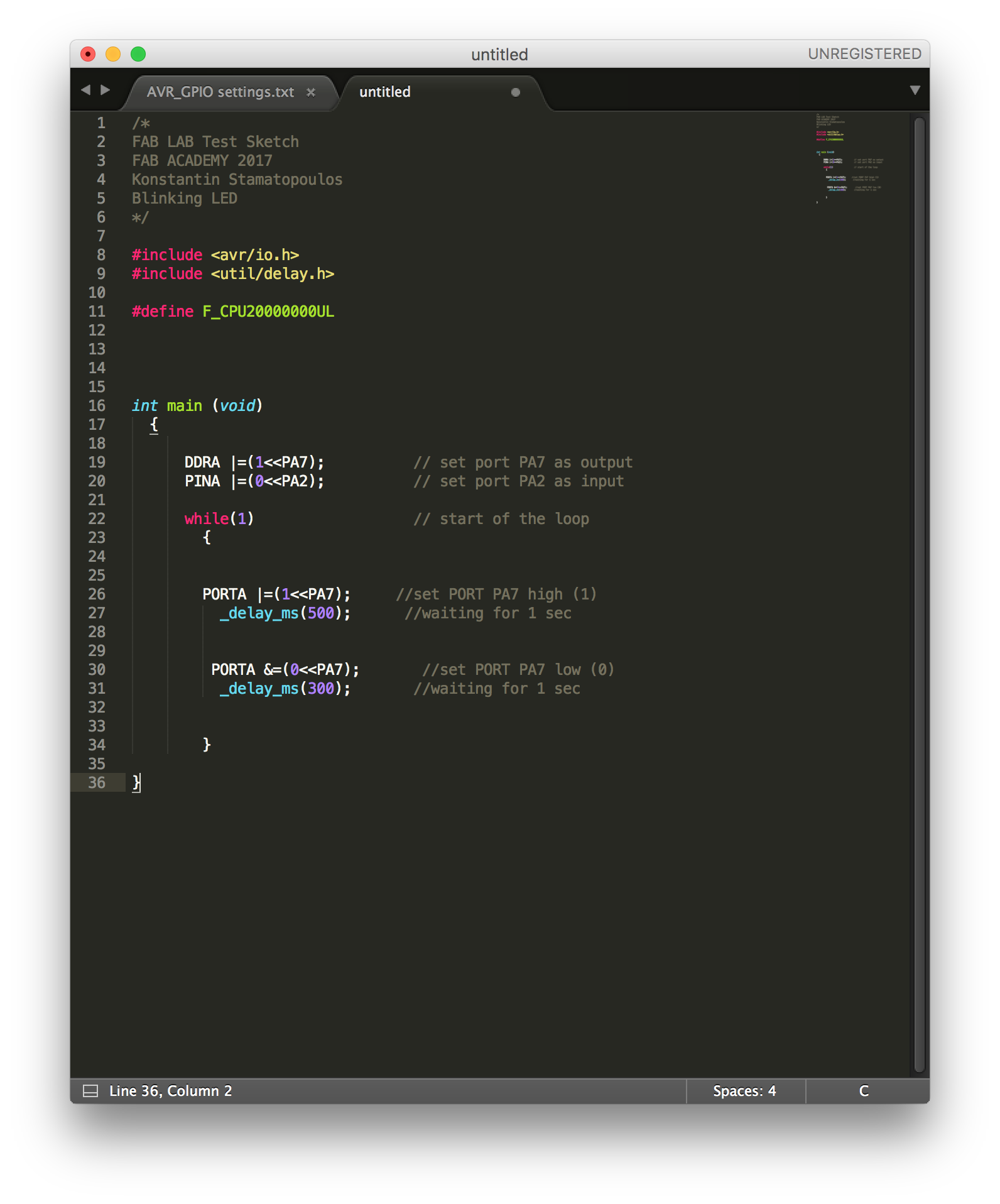
Luckily to fulfill this weeks task, it was enough to write a simple c-programm, that for example let a LED blink or, if available use a button to do something. Below are my two scripts in c that worked perfect on my board. The one is just blinking, where the frequency can be set by changing the values in the lines with the "_delay_ms" and the second one switches the LED on by pushing the button.
In the code below just before the loop starts I assigned the in and outputs to the DDRA (Data Direction Register)
and the PINA by setting a 1 for output and a 0 for input. The same values - 1/0 - within the loop stand for high and low - what means there is a signal (high) or there is none (low). In my case it simulates a function of a switch - like on and off, and to control the blinking frequency each state comes with a delay that can be changed individually.Luckily to fulfill this weeks task, it was enough to write a simple c-programm, that for example let a LED blink or, if available use a button to do something. Below are my two scripts in c that worked perfect on my board. The one is just blinking, where the frequency can be set by changing the values in the lines with the "_delay_ms" and the second one switches the LED on by pushing the button.
In the code below just before the loop starts I assigned the in and outputs to the DDRA (Data Direction Register)
On the second sketch I used a button as an input device - simple to switch on a LED. The first part of the sketch is equal to the first sketch, by assigning in and outputs. The difference starts with the loop, at the beginning the PIN PA2 is sensed if it is pressed or not.
With the following lines each state is assigned - 0b00000100 = high = 1 = pressed and 0b11111011 = low = 0 = not pressed.
/*
FAB LAB Test Sketch
FAB ACADEMY 2017
Konstantin Stamatopoulos
Blinking LED
*/

#include <avr/io.h>		// including libraries
#include <util/delay.h>		// including libraries

#define F_CPU20000000UL		// ucontroller speed - here 20Mhz

int main (void)			// program core start
  {

      DDRA |=(1<<PA7);		// set port PA7 as output
      PINA |=(0<<PA2);		// set port PA2 as input

      while(1)			// start of the loop
        {

        PORTA |=(1<<PA7);	// set PORT PA7 high (1)
          _delay_ms(500);      	// waiting for 0.5 sec

         PORTA &=(0<<PA7);	// set PORT PA7 low (0)
          _delay_ms(300);	// waiting for 0.3 sec

        }

}
...and...
/*
FAB LAB Test Sketch
FAB ACADEMY 2017
Konstantin Stamatopoulos
Push Button
*/

#include <avr/io.h>		// including libraries
#include <util/delay.h>		// including libraries

#define F_CPU20000000UL		// ucontroller speed - here 20Mhz

int main (void)			// program core start
  {

      DDRA |=(1<<PA7);		// set port PA7 as output
      PINA |=(0<<PA2);		// set port PA2 as input

      while(1)			// start of the loop
        {

 if (bit_is_clear(PINA, PA2)) {	// look for button press

		/* equivalent to if ((PIND & (1 << PD2)) == 0 ){ */

        PORTA = 0b00000100;	// button pressed
        }

        else {			// button not pressed

        PORTA = 0b11111011;

        }

      }				// End event loop
  return (0);

}

}Below are some screen shots I made while I was using the Sublime editor and for compiling and uploading of the codes the Arduino IDE.

Since the Datasheet is a Databook of over 230 pages I focused on the pinout pages
blink c code in
pushbtn c code
blink / ardunio IDE

pushbtn / arduino IDE
On the image of the datasheet above I marked the pins yellow that are important for any communication e.g. programming and the ones with the red arrow I used for my assignment - PA7 I defined as an output and PA2 as an input. - Already in mind to keep the MOSI/MISO etc free for any programming...The 2 pins left upper corner named XTAL1/2 are reserved more or less for an external oscilator or crystal.
Finally here a small clip, where I loaded both sketches to see if everything workes as it should.
ISSUES:
Since I'm a totally beginner in programming I guess I have to get use to the c structure. I get still a bit confused about the adressing of the three registers of the avr chip - but it's getting better. Untill I have it totally memorized i'm using a "cheat sheet" where I have writen all important informations - I think ?! But as doing this for the first time I had suprinsingly view errors/issues - like setting wrong port or missing a bracket.
Extra
After doing the programming with the arduino uno my instructor asked me to do it with my fabISP since it was my first fully working piece of selfmade electronics. So I connected the two boards through the ISP pinheader and I powered the helloworld board seperately with the fdti cable. For this attempt I also used the Arduino IDE. It worked fine! to get my fabISP running under the ArduinoIDE, I had to choose the right settings in the menu - tools. I selected the right board, the processor in use, the clock speed and of course the kind of programmer - here the USBTinyISP. Below the comment out put of the Arduino IDE.

the wiring of the fabISP and the hello board
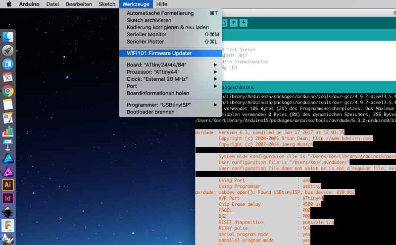
the menu settings
the programming through the Arduino IDE
avrdude: Version 6.3, compiled on Jan 17 2017 at 12:01:35
         Copyright (c) 2000-2005 Brian Dean, http://www.bdmicro.com/
         Copyright (c) 2007-2014 Joerg Wunsch

         System wide configuration file is "/Users/Kon/Library/Arduino15/packages/arduino/tools/avrdude/6.3.0-arduino9/etc/avrdude.conf"
         User configuration file is "/Users/Kon/.avrduderc"
         User configuration file does not exist or is not a regular file, skipping

         Using Port                    : usb
         Using Programmer              : usbtiny
avrdude: usbdev_open(): Found USBtinyISP, bus:device: 020:012
         AVR Part                      : ATtiny44
         Chip Erase delay              : 4500 us
         PAGEL                         : P00
         BS2                           : P00
         RESET disposition             : possible i/o
         RETRY pulse                   : SCK
         serial program mode           : yes
         parallel program mode         : yes
         Timeout                       : 200
         StabDelay                     : 100
         CmdexeDelay                   : 25
         SyncLoops                     : 32
         ByteDelay                     : 0
         PollIndex                     : 3
         PollValue                     : 0x53
         Memory Detail                 :

                                  Block Poll               Page                       Polled
           Memory Type Mode Delay Size  Indx Paged  Size   Size #Pages MinW  MaxW   ReadBack
           ----------- ---- ----- ----- ---- ------ ------ ---- ------ ----- ----- ---------
           eeprom        65     6     4    0 no        256    4      0  4000  4500 0xff 0xff
           flash         65     6    32    0 yes      4096   64     64  4500  4500 0xff 0xff
           signature      0     0     0    0 no          3    0      0     0     0 0x00 0x00
           lock           0     0     0    0 no          1    0      0  9000  9000 0x00 0x00
           lfuse          0     0     0    0 no          1    0      0  9000  9000 0x00 0x00
           hfuse          0     0     0    0 no          1    0      0  9000  9000 0x00 0x00
           efuse          0     0     0    0 no          1    0      0  9000  9000 0x00 0x00
           calibration    0     0     0    0 no          1    0      0     0     0 0x00 0x00

         Programmer Type : USBtiny
         Description     : USBtiny simple USB programmer, http://www.ladyada.net/make/usbtinyisp/
avrdude: programmer operation not supported

avrdude: Using SCK period of 10 usec
avrdude: AVR device initialized and ready to accept instructions

Reading | ################################################## | 100% 0.00s

avrdude: Device signature = 0x1e9207 (probably t44)
avrdude: NOTE: "flash" memory has been specified, an erase cycle will be performed
         To disable this feature, specify the -D option.
avrdude: erasing chip
avrdude: Using SCK period of 10 usec
avrdude: reading input file "/var/folders/sv/s9p338wx41l_hn27rwnwdd400000gn/T/arduino_build_243458/Blink.ino.hex"
avrdude: writing flash (106 bytes):

Writing | ################################################## | 100% 0.09s

avrdude: 106 bytes of flash written
avrdude: verifying flash memory against /var/folders/sv/s9p338wx41l_hn27rwnwdd400000gn/T/arduino_build_243458/Blink.ino.hex:
avrdude: load data flash data from input file /var/folders/sv/s9p338wx41l_hn27rwnwdd400000gn/T/arduino_build_243458/Blink.ino.hex:
avrdude: input file /var/folders/sv/s9p338wx41l_hn27rwnwdd400000gn/T/arduino_build_243458/Blink.ino.hex contains 106 bytes
avrdude: reading on-chip flash data:

Reading | ################################################## | 100% 0.12s

avrdude: verifying ...
avrdude: 106 bytes of flash verified

avrdude done.  Thank you.
here I did the board programming on the commandline
before the programming on the commandline, I had to change in the makefile the right name of the processor into t44 as highlighted in the image below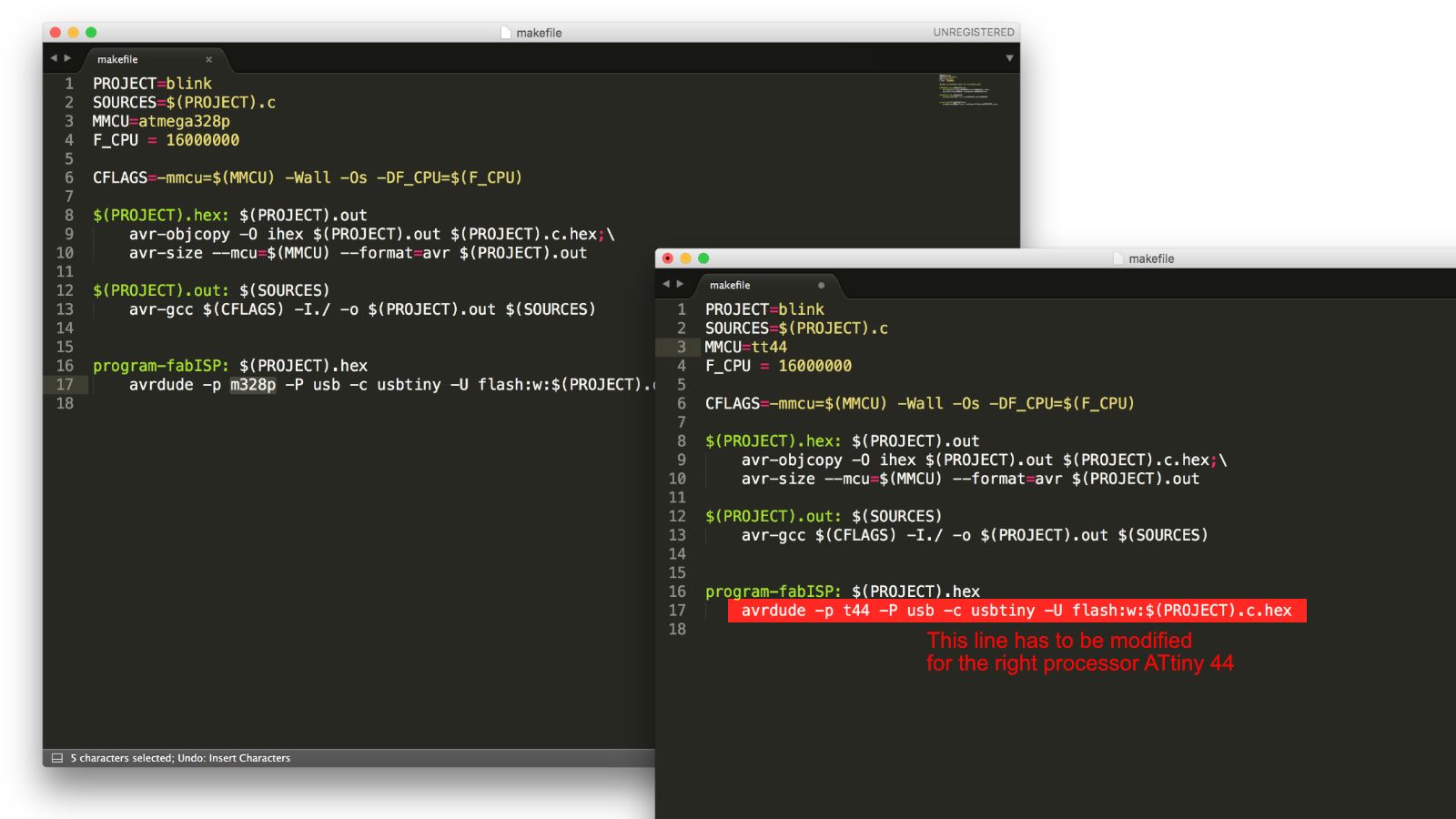
modification of the makefile
KonMax:upload Kon$ make program-fabISP
avr-gcc -mmcu=attiny44 -Wall -Os -DF_CPU=20000000 -I./ -o blink.out blink.c
avr-objcopy -O ihex blink.out blink.c.hex;\
	avr-size --mcu=attiny44 --format=avr blink.out
AVR Memory Usage
----------------
Device: attiny44

Program:     106 bytes (2.6% Full)
(.text + .data + .bootloader)

Data:          0 bytes (0.0% Full)
(.data + .bss + .noinit)


avrdude -p t44 -P usb -c usbtiny -U flash:w:blink.c.hex

avrdude: AVR device initialized and ready to accept instructions

Reading | ################################################## | 100% 0.00s

avrdude: Device signature = 0x1e9207
avrdude: NOTE: "flash" memory has been specified, an erase cycle will be performed
         To disable this feature, specify the -D option.
avrdude: erasing chip
avrdude: reading input file "blink.c.hex"
avrdude: input file blink.c.hex auto detected as Intel Hex
avrdude: writing flash (106 bytes):

Writing | ################################################## | 100% 0.11s

avrdude: 106 bytes of flash written
avrdude: verifying flash memory against blink.c.hex:
avrdude: load data flash data from input file blink.c.hex:
avrdude: input file blink.c.hex auto detected as Intel Hex
avrdude: input file blink.c.hex contains 106 bytes
avrdude: reading on-chip flash data:

Reading | ################################################## | 100% 0.13s

avrdude: verifying ...
avrdude: 106 bytes of flash verified

avrdude: safemode: Fuses OK (H:FF, E:DF, L:FE)

avrdude done.  Thank you.

KonMax:upload Kon$
Downloads

This work is licensed under a
Creative Commons
Attribution-NonCommercial-ShareAlike 4.0 International License.