#07week
computer controlled machining
tasks- - make something big
This weeks assignment was about cnc machining and making something "big". So at first we had to design something with the tools 2D/3D we learnt in the 2nd week - so basically this tasks build somehow on the previous one.
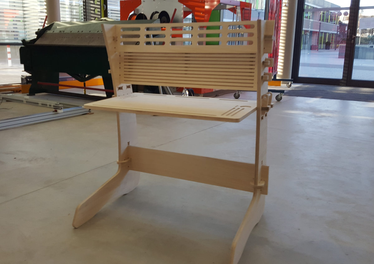
I had to make my mind up what to make - sounds simple but it's not. Not really. But when you have Family with children you will have plenty ideas that are waiting to get real. So this time I decided to make a desk for my 5 year old son. Since kids grow fast in that age, the desk should be variable in height.
At first I made a sketch on a sheet paper - that's how I always start because I have a idea but no clear view how exactly the final object will look like. That way is much easier to design something because there are no software issues to follow or that limits your action. After I found that the design on the paper will meet my expectation, I scanned the sketch so that I could use it as a blueprint for the cad file. Below I included a view screenshot of the workflow.
As you could see I decided to design the desk within Autodesk's Fusion 360 instead of Rhino3D, one of the reasons was that I want to get better in Fusion - I have some years experience in Rhino and I will continue to work with but from the application structure it is more a freeform cad design tool with it's own advantages and if I continue to work with both applications I will have the best out of two "worlds", if I may say so.
Let's get back to Fusion, one important feature is, it's parametric. That is as for all serious industrial-level CAD applications a must. It gives me the possibility to make my design and change afterwards some key-features on demand. In my case the slot size or if I want to scale my desk for use with an adult or a teen also the complete design.
In these cases I have to change just the values of my user defined variables and the application will recalculate the constraints and fit the design as it was meant.
Below the next screenshots that document my next steps within Fusion...
After checking the fit of all elements I designed for the desk I exported them as dxf file but not the extruded bodies/components just the 2D sketches. This because the design - if we break it down is just a 2D design that will be put togehter to a 3D object - similar to our assignment of the 3rd week "computer-controlled cutting"
The procedure in Fusion is a bit different as you may expect. Instead of selecting the export command from the main menu, what is possible, but it will not allow you or even give you the possibility to export any 2D sketches as dxf file - just 3D formats like iges, step, fusion f3d or two other. I for instance had expected to have the choice what i want to export from the menu.
Luckily I found out that I have to select the sketch within the fusion browsertree and with the right click menu I had the "hidden" option to export the sketch as dxf. That's somehow weird. But since I know this I can live and work with that.
After exporting all sketches as dxf, I started Rhino3D. For me personally some workflows or actions are more intuitive in Rhino done than in any other cad tools I get to work with. In my case I had to nest them manually to achieve the least waste of my material. And also I have some usefull functions within Rhino to analyze and repair the sketches for errors like open curves and so.
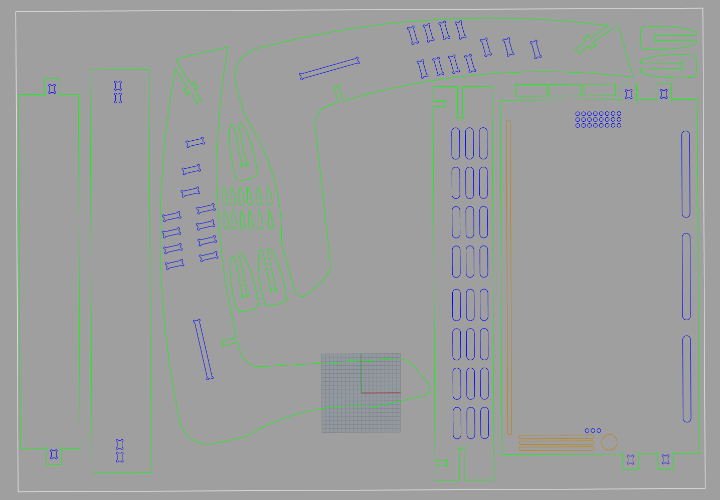
On the following screenshots you can see my alignment of the sketches in Rhino. I tried to optimize the layout as much as I could, not to waste any material. I think I did a good job. I selected those curves where the tool of the cnc machine has to mill on the outside of the path and moved them to a seperate layer. Next I selected those parts that has to be milled on the inside, like slots and holes, and those I moved also to an own layer and a final same procedure for those elements that has to be milled as pocket or as an engraving not a cut through. As you can see on the screenshot I've five different, colored layers named after their properties. That is one important thing throughout my activities I've learned at the very beginning her at the Fab Acadamy - use a naming that is precisely and won't allow any misunderstanding. So I'm endeavored to adapt the common terms from any subject area that is used within the FabLabs and the Fab Academy.
That is even more important as we are an international network and usually any help request or question posted will get attention from all over the network (world). Finally I exported my arrangement as dxf file with the settings R12 Lines & Arcs, this setting is somehow essential because with another setting the resulting file won't be processed correctly. Then I transferred the file via an usb stick to the control computer of the cnc machine, where I had to make the correct settings for the milling.

my paper sketch

side panel sketch
side panel sketch with dimensions
here a closeup of the upper area of the side panel

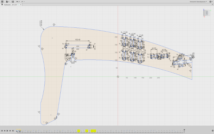
this is the sketch from the desk with dimensions

...here the lower board, underneath the desk
...and the closeup of the slot area
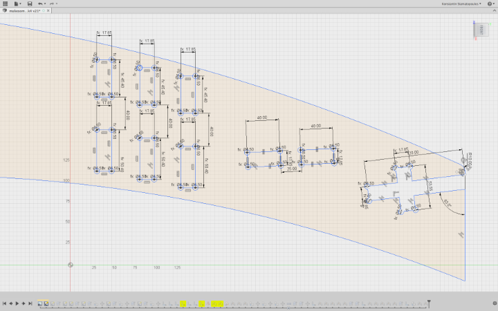
...the sketch of the shelf board, the grooves will take 5mm thick boards as small shelfs

here the closeup of the shelf board with the grooves

...and the final from the big parts - the top board. in the left upper corner is the little stop block

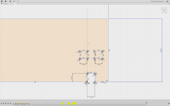
this is the joint clamp that fixes the side panels to the lower board

...and the plugs - the "little brothers" of the clamp
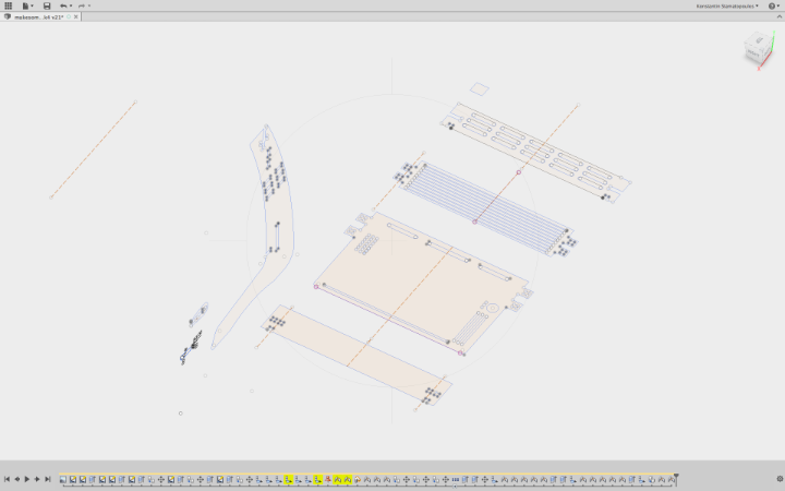
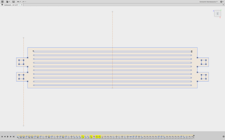
...here the sketch overview within Fusion

Here we see clearly that often the exported/imported curves are not closed...

This now was my first attempt, for nesting the parts within Rhino3D
...the second attempt after a view change...

...and the final layout.
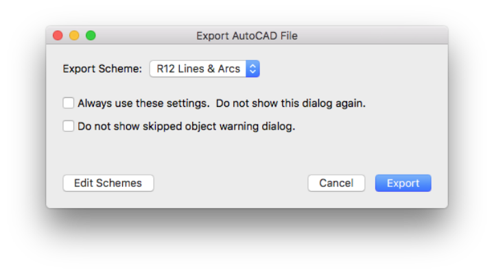
This are the right settings for exporting dxf from Rhino
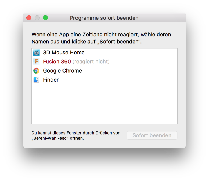
..against all odds...Fusion chrashed...

...and a report for the Autodesk Support Team
CNC Machine settings
The settings for the cnc machine as follows are important, as a wrong setting can result in a broken tool or even greater damage. So taking time to go throroughly all required steps is the first rule when working on this kind of machines.
Below now I'll describe the meaning of each setting and my values.
Safe-Z
(a)...means I have to define the height the tool will be retracted from the surface to make any moves that have nothing to do with the active milling. Those are the so called travel movements. With this setting we prevent that hte tool will hit by accident any obstacle on the surface - the value should be greater than the highest point on the material.Start-Z
(b)...is where the machine starts with the milling. It's recommanded to set the value sightly higher &40;0.1mm / 0.039 inch&41; so that the dive-in of the tool will be with less load for the advantage of material and tool equal.Final-Z
(c)...is the value where the operator defines the finish depth for the tool. This depends on the material thickness and what work has to be done. With work is meant if the process is a cut-through or an engraving/pocketing. In my case now my material had a thickness of 17.80mm/0.7 inch and since I wanted to make a cut-through, I added an extra of .01mm/ .0039 inch. Our CNC Machine is very precise so this small value is enough to ensure a good result.Z-Increment
(d)...is the value where the operator defines how deep every step of the tool will go - as for hard materials usually a couple of step downs are needed to machine the workpiece. And as a rule of thumb a good value is the half of the tool diameter - again depending on the material. The harder the material the smaller the value, and vice versa in softer material a higher value is possible and will safe a good amount on machining time. Also the tool diameter counts in this rule a bigger tool can obviously manage a higher load and value than a smaller one. Again in my case with my material (Plywood ca. 17.80mm/.7 inch certain not a hard one) a value of 2.6mm/0.102362 inch per step is a resonable choice. Taking this into the calculation gives us 7 steps plus the final step for the Final-Z. As an example: if a full process of the first step will take, let's say 2 minutes, then the complete machining of the workpiece will take an estimated (7+1) *2 minutes = 16 minutes. Not included any additional moves.With this knowledge now it is undersandable that even such a easy or simple geometry takes some time...
Feedrate
(e) ...is simple said just the speed that the tool moves through the workpiece. And as with the Z-Increment, the Feedrate depends on the kind of material and the tool in use. Luckily there exist reliable lists where the feedrate and the incrementation can be read out for diverse materials and tools.PlungeRate
(f) ...is the setting that defines the speed of the tool by going into the workpiece - besides the Feedrate a very important value that decides over the durability of the tool.ToolNumber
(g) ...with this setting you tell the machine what tool to use, this has only a meaning if an automatic toolchanger is available. Below this field is the stteing for the tool diameter (lucky we have one here in our FabLab KaLi)MakeBridges
(h) ...this fields here are for bridging the object within the workpiece. This is if the the object that will milled or routed out of the workpiece will eventually won't stick to the machine table. Then small "bridges" that are left over from the tool and placed around the finshed object, take care that it will stay at the position. Because if not the object may move and will be caught by the rotating tool and this could cause a crack of hte object or the tool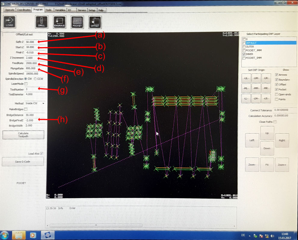
CNC v4.x - the operating software for the CNC MAchine

our automatic tool-changer...

...here I'm defining the x/y zero position with a laser mark

...the calculated toolpaths for the slots/inside cuts

...and the tool paths for the pockets/engraved areas...
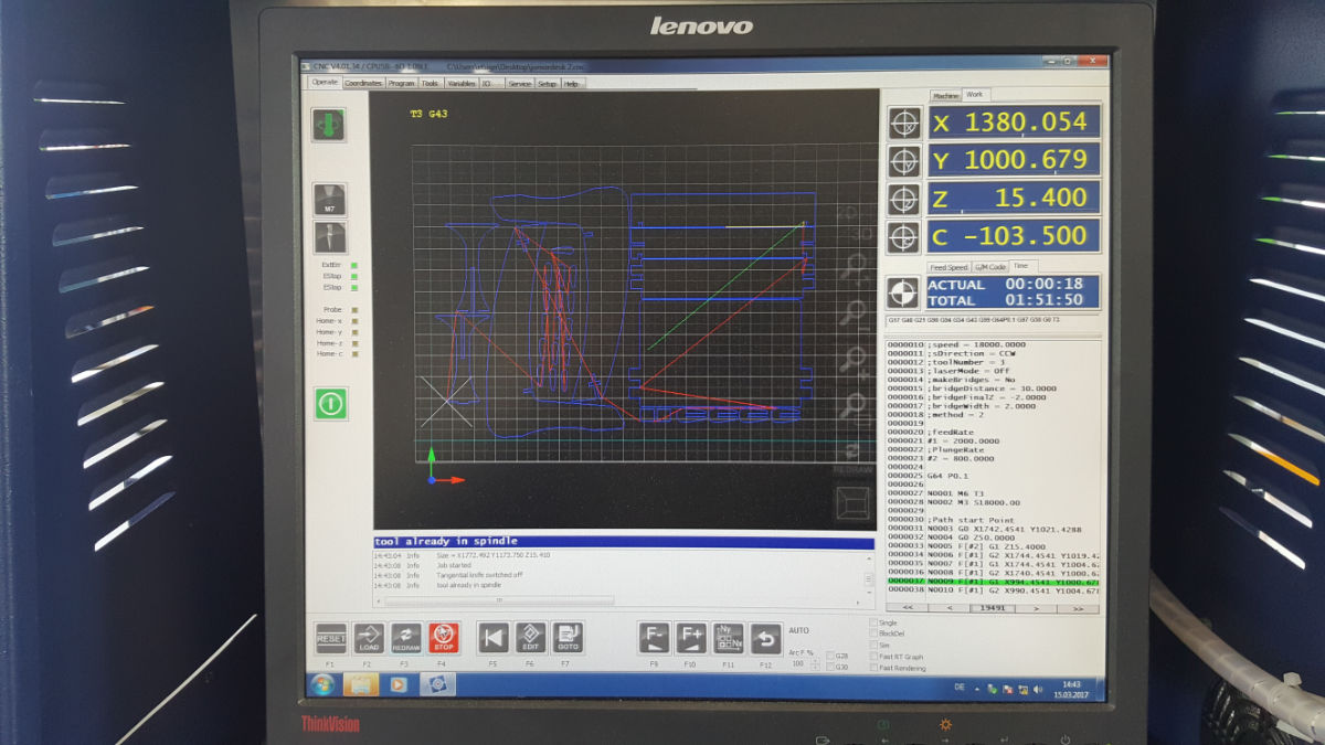
...last but not least - the outside cuts...

...and here it is visual what paths are cut already - they appear in yellow
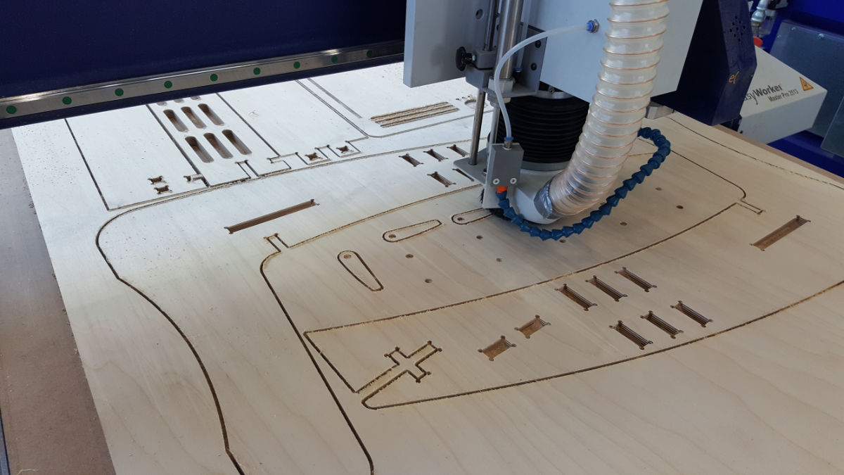
...here the real view
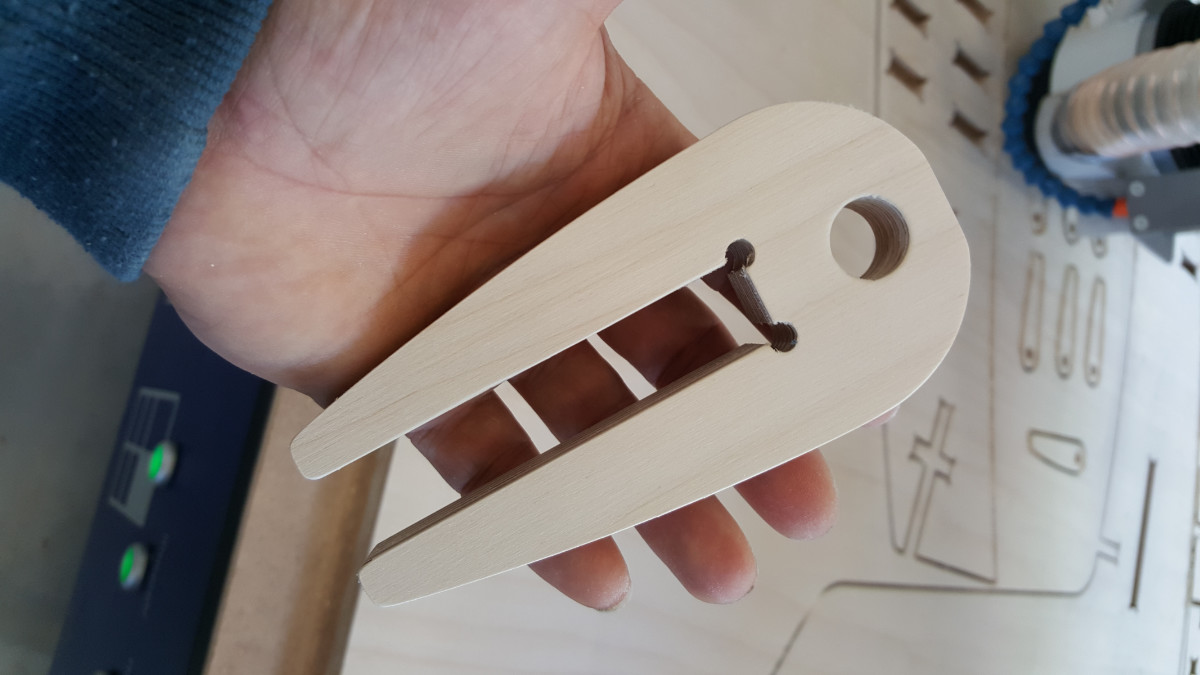
...a final element one of two clamps...

...I present you the life-size puzzle for grown-ups
...here the real thing
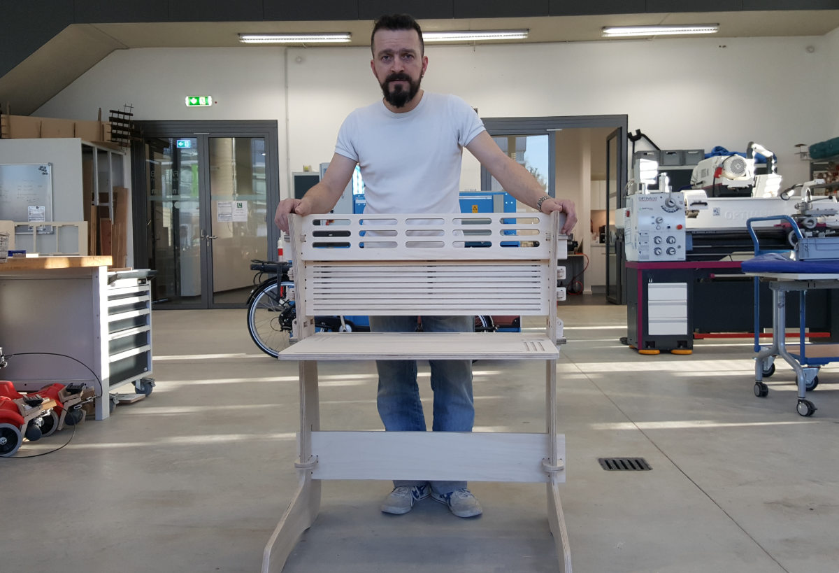
My Heroshot...
CNC v4.x - the operating software for the CNC MAchine
Resumee
After I lost twice my complete fusion file so that I was forced to restart the design process - I came up with some kind of routine of backing up my work after any important or major changes. It happend really a third time but this time it took my just a view seconds to recover the data. A positive result out of this experience is not this kind of routine I'm getting use to it also that with every new start my design workflow within Fusion got better and more fluent. And every time it took less time to rebuild the file. The way Autodesk handles the export function in Fusion irritated me and still it's a bit weird, but as soon I found out were to find that function I was ok with it. Also that I have to export each sketch separately is not very handy.
One thing that came up when I was ready to take my files to the CNC, was the through in the corners of the joints/slots. I used a diameter of 5.5mm/0.217inch and I thought that is plenty room for fitting the pieces together. But because I aligned them on the corner with their centerpoint the through wasn't big enough for the tool (4mm/0.177inch dia.)to pass. I hereby say thank you to Karsten our Director of the FabLab here for pointing this out to me.
So I went back to my computer and luckily made use of the parametric features of Fusion and the custom made variables so it took just a view minutes to change the values and safe the adjusted files. And you can see the result of my work on the picture.
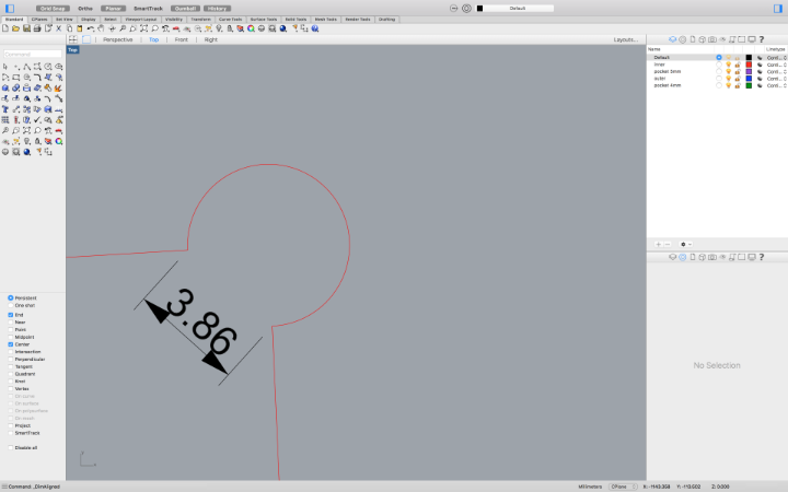
...checking the distance of the corner/"dogbone"
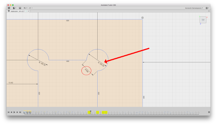
...after adjusting the diameter of the "dogbones"!
My experience with the routing of plywood is for the first time quite succesful I would say - even that I have calculated 0.04mm/0.0015inch more for the slots I found my self reworking manually with sanding paper and a file the slots a bit - and not all of them. I considered this in my Design now and extended the dimensions therfor. A bit more clearence is no problem with my design as I have the plugs and the clamps for final fixture and they do a perfect job.
Finally I have to say that i have to design a chair that fits into this design - my son is asking for...
Downloads

This work is licensed under a
Creative Commons
Attribution-NonCommercial-ShareAlike 4.0 International License.