#10week
Output Devices
tasks- - add an output device to a microcontroller board you've designed and program it to do something
For this week we had to made a new microcontroller board and attach some i/o devices to it. And to control them to do something. Also we could use the Arduino IDE if we made a own board. So for me the first part for this assignment was to make a arduino compatible board on my own to use it with the Arduino IDE. I decided to take a chance on my instructors, Daniele Ingrassia's board the satshakit and modify it to my needs. I also did some redesign to beautify a bit the layout. My plan was to use:
(1) - Either a stepper motor or a BLDC Motor
(2) - a LCD.
I added two LEDs to the RX/TX ports as a visual indicator for communication on the serial port. Furthermore two pinheads for power (vcc) and ground (GND) for attaching any i/o devices that are suitable. At first I downloaded the datasheets from those components that I would like to use: LCD-Display, Graphical Display,
One issue happend when I was drilling the pinholder holes in the board. I accidentely moved the board so drilled into a trace so I had to bridge the gap with extra solder
As I am a totally beginner regarding programming I did some research using the web. I went through certain forums and sites referencing programming and arduino sketching. After reading the Datasheet of my LCD Display I tried a view sketches I found on different sites to select one that was suitable for my needs. At first I tried them without changing the code - this was a lesson for me because most of the examples used a different typ of display. It took a while for me to findout where the error was. I had to initialise the display by his I2C port address, which I didn't knew. And since I am not an experienced coder I had some difficulties to find this out. But I knew what I have to search for so after a while I found this helpfull site with tips and tricks also for beginners like me. There i found a handy sketch called I2C port scanner that helped me to get the needed information and me going.
 here the EAGLE schematics including the modifications
 ...and the corresponding PCB...
 ...and the exported PNG file for the FABMODULS
 ...and the cut-out file - there's not much to see....
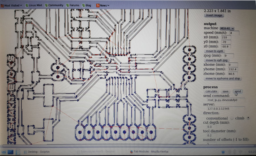 ...the user interface of the FABMODULS...
 this is an actual view from the milling...
 ...and another one...
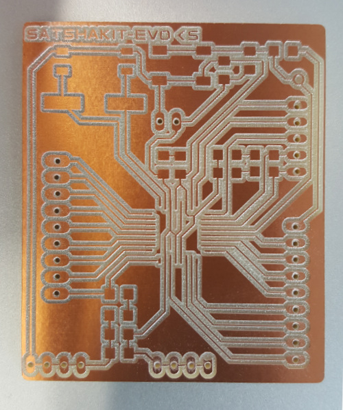 ...just finished milling!
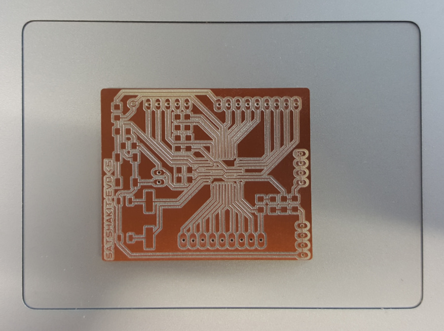 ...one closeer look...
 This was the first test - so called "smoke test" - luckily it's a Nonsmoker!
 the backside of my output device
 here is the wiring schematics for the setup...
 problems problems problems....but I found the error and fixed it! It was the broken trace to the reset!
 After using the portscan sketch I was able to initialise the display with the right port address and the sketch worked fine
/*
FAB LAB Test Sketch
FAB ACADEMY 2017
Konstantin Stamatopoulos
Output device
*/

#include
#include                           //this is the library for the LCD Display
#include             //this is the library for the LCD I2C communication
LiquidCrystal_I2C lcd(0x27, 2, 1, 0, 4, 5, 6, 7, 3, POSITIVE);
                                          //setting LCD Addr, En, Rw, Rs, d4, d5, d6, d7, backlightpin, polarity


void setup() {
lcd.begin(20, 4);                         //initialisation of the LCD screen 16 characters and 2 lines
lcd.backlight();                          // backlight on
lcd.clear();                              // clears lcd screen

lcd.print("Fab Academy 2017");            //prints out message to LCD screen
delay(3000);                              // delay / wait for 3 seconds
lcd.clear();                              // clears lcd screen

lcd.print("#w10 Assignment");            //prints out message to LCD screen
delay(3000);                             // delay / wait for 3 seconds
//lcd.clear();                             // clears lcd screen
lcd.setCursor(0,1);
lcd.print("Student #456");               //prints out message to LCD screen
delay(3000);                             // delay / wait for 3 seconds

lcd.setCursor(0,2);
lcd.print("Konstantin Stam.");                 //prints out message to LCD screen
delay(3000);                             // delay / wait for 3 seconds
//lcd.clear();
lcd.setCursor(0,4);
lcd.print("FabLab Kamp Lintfort");      //prints out message to LCD screen
delay(3000);                            // delay / wait for 3 seconds
}

void loop() {
{
lcd.clear();
delay(500);                            // delay / wait for half second
lcd.setCursor(0, 0);                   //assigning the position of the temp value 1st position and 1st line
lcd.print("Hi Neil");

lcd.setCursor(0, 1);                  //assigning the position of the temp value 1st position and 2nd line
lcd.print("Hi Fab Academy");

delay(10000);                         // delay / wait for 10 seconds
}

}
Downloads & Ressources

This work is licensed under a
Creative Commons
Attribution-NonCommercial-ShareAlike 4.0 International License.