#15week
networking & communications
tasks
- - design and build a wired and/or wireless network connecting at least two processors
For this week assignment we had to setup up a network between at least two microprocessors we have built ourselfs - so I made at first a second microprocessor board. I going to do at first a wired communication through I2C because this is one of the most basic connection and realistic seen it is the right order to do this first. If I have enough time I will try to do also a wifi connection using the ESP8266-12F. Despite the fact that this little modul has on its own the capability the be used without any external microprocessor because of its builtin functionality - Neil asked as not to do so - more to use it as an ordinary extension for our own boards.
So I had to made also this little ESP board with the required pinouts and also the voltage regulation from 5V to 3.3V.
I like the idea of modularity, to have a separate modul for each task - that would make any changes or repairs easier and hasslefree, I believe.
 At the beginning a line up of all boards I made for this assignment ...
 ...here is a schematics how the I2C protocol works
 ...here is the basic setup, it works up to 112 devices
 I setup a ESP8266 - for later - here a front and back view - I didn't liked that the regulator stood up that high so placed it on the back side..
 After I made my boards I did some research about the I2C communication protocol and I reviewed some examples to get a feeling about it. I found some good examples and I picked one that I modified to use for my assignment. The source and the link to it I will post at the end of this page. Actually I wanted to to the wired communication at least with three boards - I made three in total but two of the new boards didn't work although they looked alright and clean. I've been told that this can happen from time to time and I should go on with my assignment what I sure did. Following a view photos of my setup and wiring, and the screenshots also.
 I used the board with the colored pins as the masterboard..
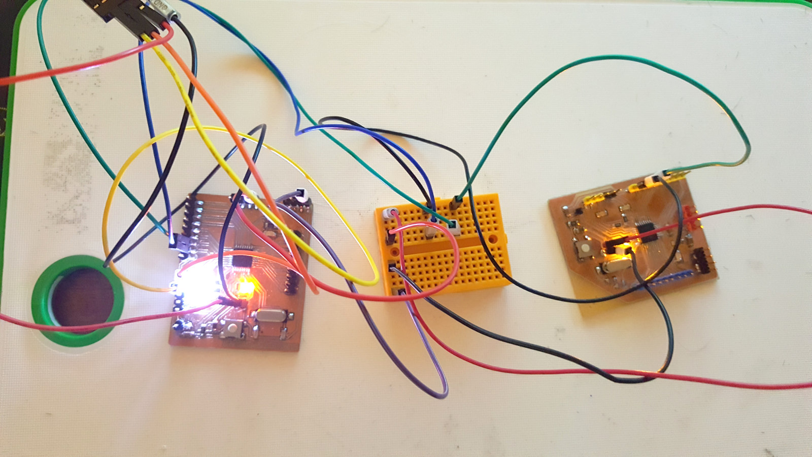 ...finally here the live wiring with the two boards - powered through the fdti cable
 the screenshot with the port selection
 ...and the screenshot with the serial monitor readings
 the sketch for the masterboard
#include <Wire.h>

void setup() {
  Wire.begin(); // join i2c bus (address optional for master)
}

byte x = 0;

void loop() {
  Wire.beginTransmission(8);		// transmit to device #8
  Wire.write("Communication works!");	// sends five bytes
  Wire.write("1..");             	// sends one byte
  Wire.write("2..");
  Wire.write("3..");
  Wire.endTransmission();   		// stop transmitting

  x++;				        //increasing x by 1, counting up
  delay(500);			        // time delay of a half second
}
Here is a short description what the code up is actually doing on the master side.
With 'Wire.begin' we initialise or join the i2c communication. If the code runs on a master device naming the address is optional, for a masterdevice is managing the i2c network and is not limited to one specific function. Than I declare a variable for this test sketch. With 'Wire.beginTransmission(8)' as the names already says a transmission begins, the number in the brackets defines the address for the receiving device. 'Wire.write("xxx") contains and sends any information in this example it's sending a view bytes of text. And finally 'Wire.endTransmission' tells the receiving device that this is the end of the transmission.
And here is a the description what the code up is actually doing on the slave side.
With 'Wire.begin' also join the i2c communication. But for slave devices naming the address is obligatory, to avoid any malfunction or any unpredictable reactions within the network. Than I register the event of receiving any communication with 'Wire.onReceive(receiveEvent)' and Serial.begin(9600) the serial output is initialised with the speed declared in the brackets.
and the sketch for the slaves
#include <Wire.h>

void setup() {
  Wire.begin(8);                // join i2c bus with address #8
  Wire.onReceive(receiveEvent); // register event
  Serial.begin(9600);           // start serial for output
}

void loop() {
  delay(100);
}

// function that executes whenever data is received from master
// this function is registered as an event, see setup()
void receiveEvent(int howMany) {
  while (1 < Wire.available()) { // loop through all but the last
    char c = Wire.read();        // receive byte as a character
    Serial.print(c);             // print the character
  }
  int x = Wire.read();           // receive byte as an integer
  Serial.println(x);             // print the integer
}
Resumee
On the hardware side there where some issues like the not working boards and the trouble with some FDTI cables - I had to try 3 different cables to get one working. They got recognized by the system but I was not able to read out the data to the serial monitor. Only the third one worked as expected. Maybe its a driver problem, because the cables were from different manufacturer.
Software wise it can a be a simple entry point to the serial communication between different devices and now I have to go deeper into this section to understand its full capability. I will have to go through a couple examples to understand completely the I2c communication and after that I will master the wireless communication.
Ressources

This work is licensed under a
Creative Commons
Attribution-NonCommercial-ShareAlike 4.0 International License.