Machine Desing And Building
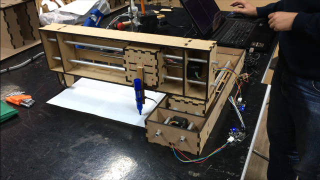
On building the Machine, I got responsible for study the programming part, besides not have any backgrount in it. It was a real challenge. I also helped Laura and Carla with some solution on the machine design, drawing and making a wheel to support the y axis weight.
Programming is already brand new for me, and dive into Python was very difficult to understand. I realized that the documentation of the MTM and gestalt nodes are all splited and hard to find and understand. It is like a maze to find the correct information on the programming, how to set and how to program the nodes to control the motors.
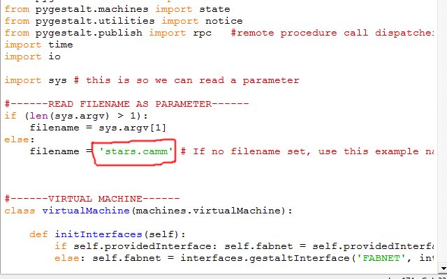
Finally I found the programs from Nadya's gitLink Here, i had to try understand what each part means. There was a lot of different files and folders and at the end, with some help from Siron I got the correct files. We found the file xy_plotter but he adivesed me that the file cannot start the name with 'x' because of a weird "windows" problem. So we changed it to axy_plotter.
Studying the code , some important functions I found was:
portName = 'name-of-your-port' - You need to know in which port on your computer the Fabnet is conected. In Windows you can find it at Device Manager
elements.leadscrew.forward(#) - Sets how much the motor rotate for each command. use 8 to ride 1 mm when you send a command that changes in 1 from the previous command.stage.xNode.setVelocityRequest(10) - Sets the speed of the axis. Be careful because after 15 the motors start to go to fast and makes some bad noises.
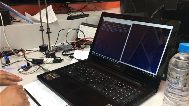
I first started testing just one node, using the file single_node.py available in Nadia's git. We got it to work using the existing FTDI cable and Fabnet to connect int he gestalts.
Siron explained us a way to use Fab Modules to the MTM. We could use files generated for the Vynil cutter and change its parameters to work in our machine.
To our machine, to travel 10 mm our commmands range in 10. In the vynil cutter to travel 10mm the code changes in around 398. So all we have to do is to divide the coordinates from the Fab Modules per 39.8, and we will get a good coordinates for our machine.
So I added a part of the code that makes this divison.
We loaded a file with a star drawing and testes the nodes. It worked pretty well.
Links to others pages i used as reference to buildind this machine:
Nadya's MTM Documentation Link here
James's MTM DocumentationLink Here
How to connect FabNet to FTDILink Here
Final Files used on this assingment Files Avaliable Here
Opportunities of improvement
- the end effector could be improved by instead of just fix the pen in the Y Axis, we could make a spring loaded pen, that make sure the pen adapts to the surface where the paper, and keep pressuring the paper to be drawed.
- We could make another axis (z axis) so the drawing wouldnt be continuous. We could use another node with stepper motor or something as a servo motor. This last case would require us some more programing work because the documentation from Nadia is only to control each node with stepper motors, not servo motors.
- We could paint or cover the nodes with vynil to make it looks better, instead of let it in the MDF.