Eletronics Prodution
Make an in-circuit Programmer by milling the PCB
making the PCB was easy to understand but was hard to put all that information in to action.
Siron, my teacher, gave me all the support and help me out a lot.
We recived our files and Siron guide us on how to operate the machine, in this case a Roland MDX-40A

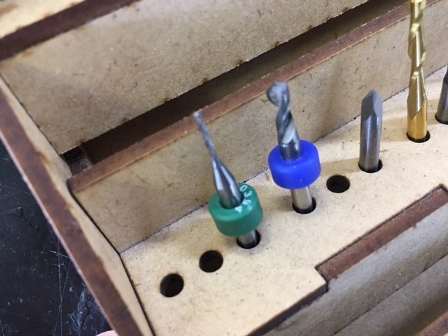
First i needed to take the "traces" and the "outlines" of my final PCB and transfer to the PC that comands the machine, after that i opened the Roland Sofware, selected the files and put the 0,4mm endmill to make the internal traces and swap to the 1mm endmill to make the outline traces.
Adding double-sided tape to the pcb
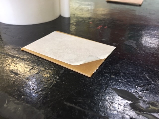
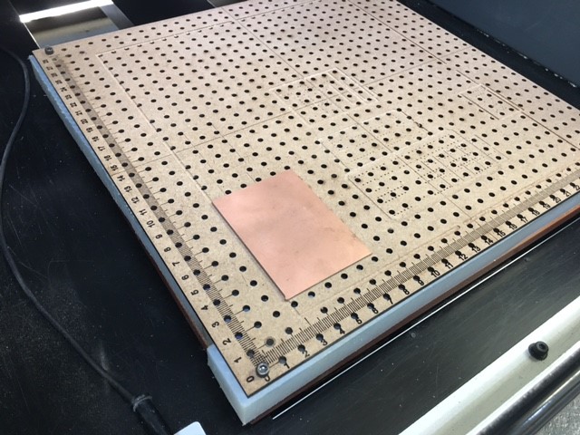
stick it on the cnc table
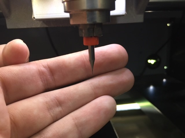
Putting the 0.4 endmill on the machine
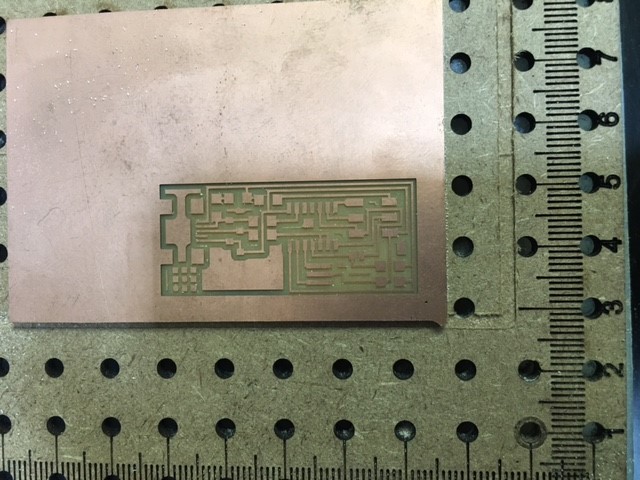
Finished the internal traces
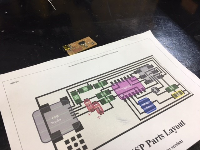
Soldering the components using the instructions
The most tecnicall and dangerous part for me was setting the z axis on the right place, too high, too low or too fast and your endmill gona break.
The trick here is to take your time and make sure your endmill is barelly touching the PCB.
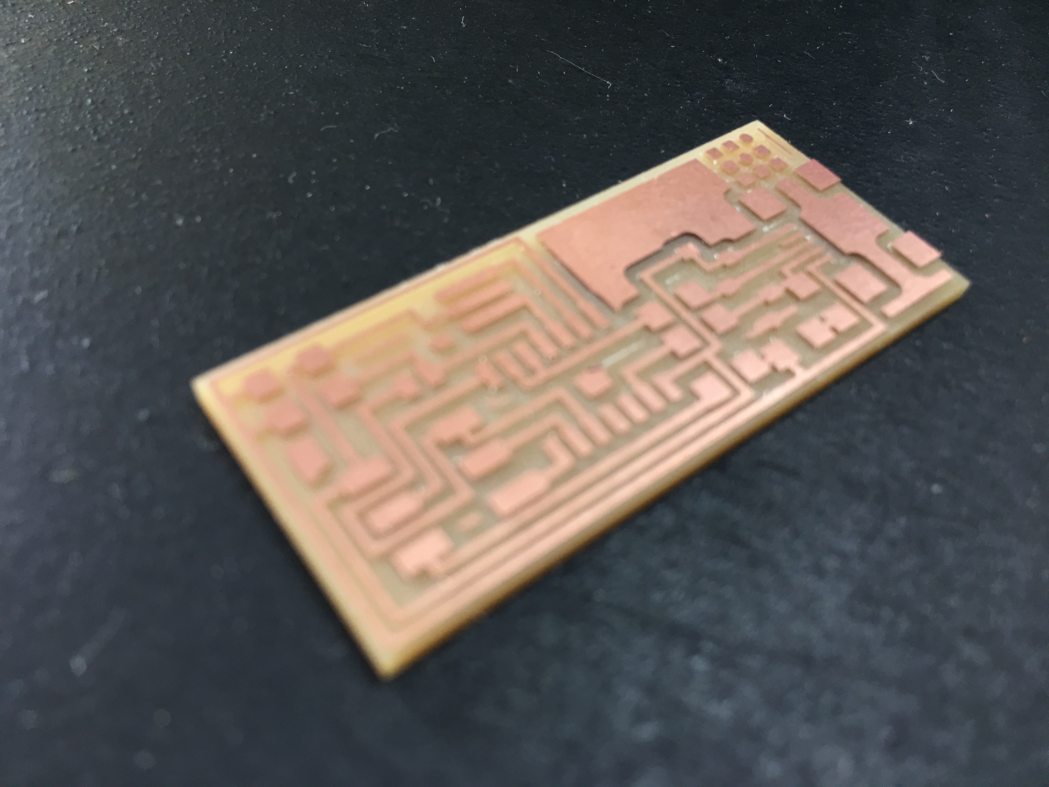
After setting the z, x and y axis you are good to start the cutting.
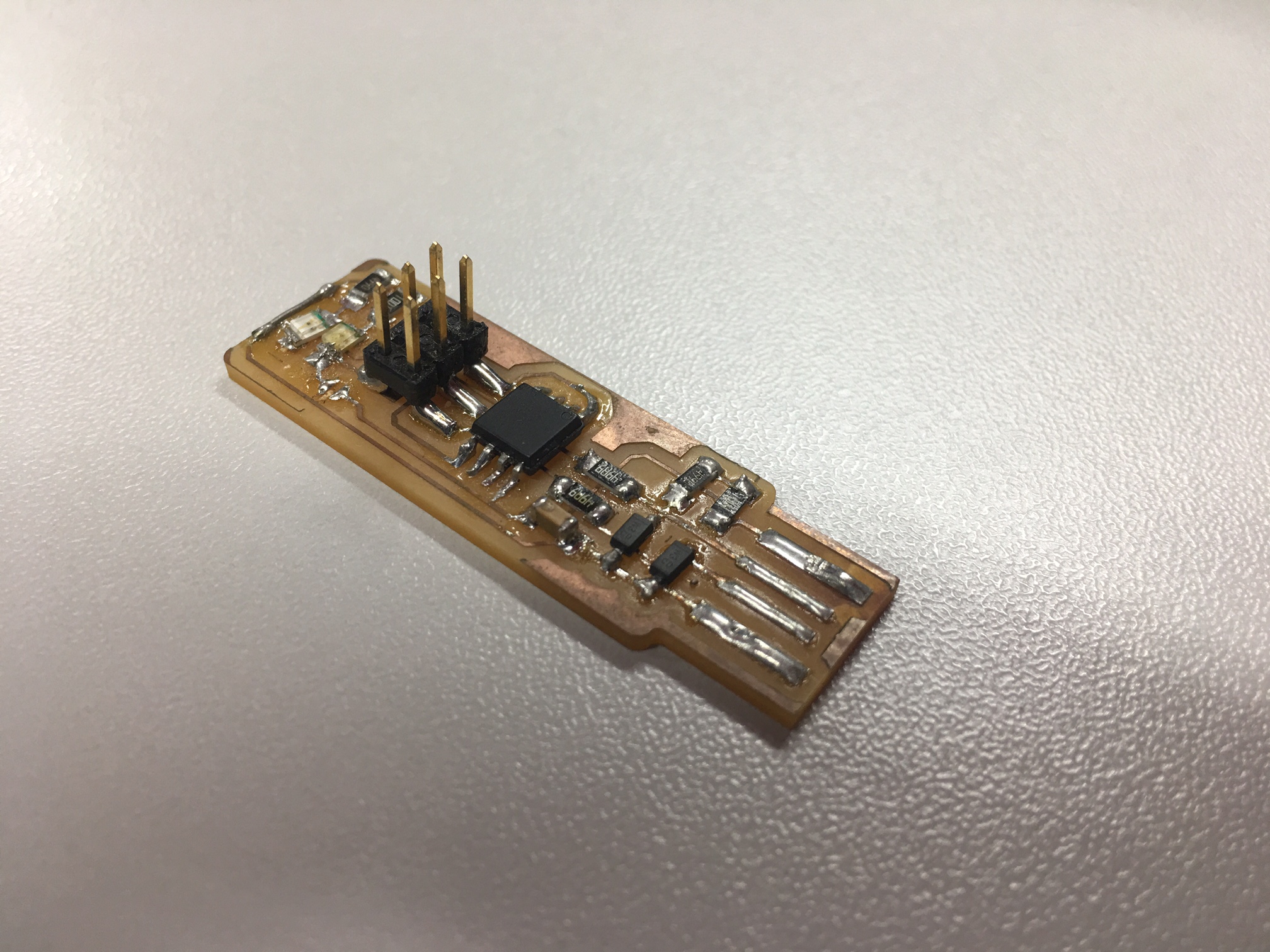
If everything is correct your PCB should look like the one in the photo above.
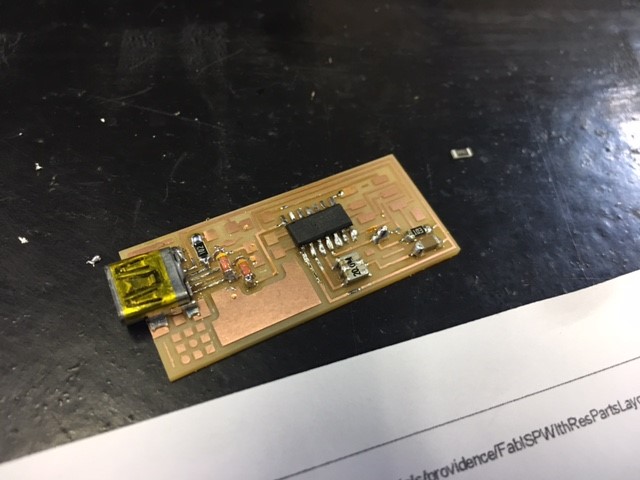
But i had some problems, the traces were peeling off from the board and I have decided to start all over again using FabTinyISP Version Click here to see the original post on the link page you can see the steps to build and program this board
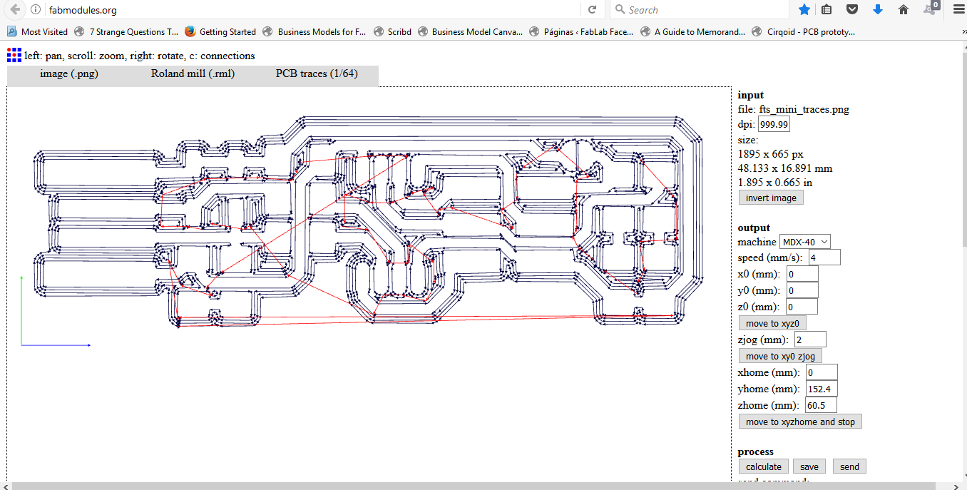
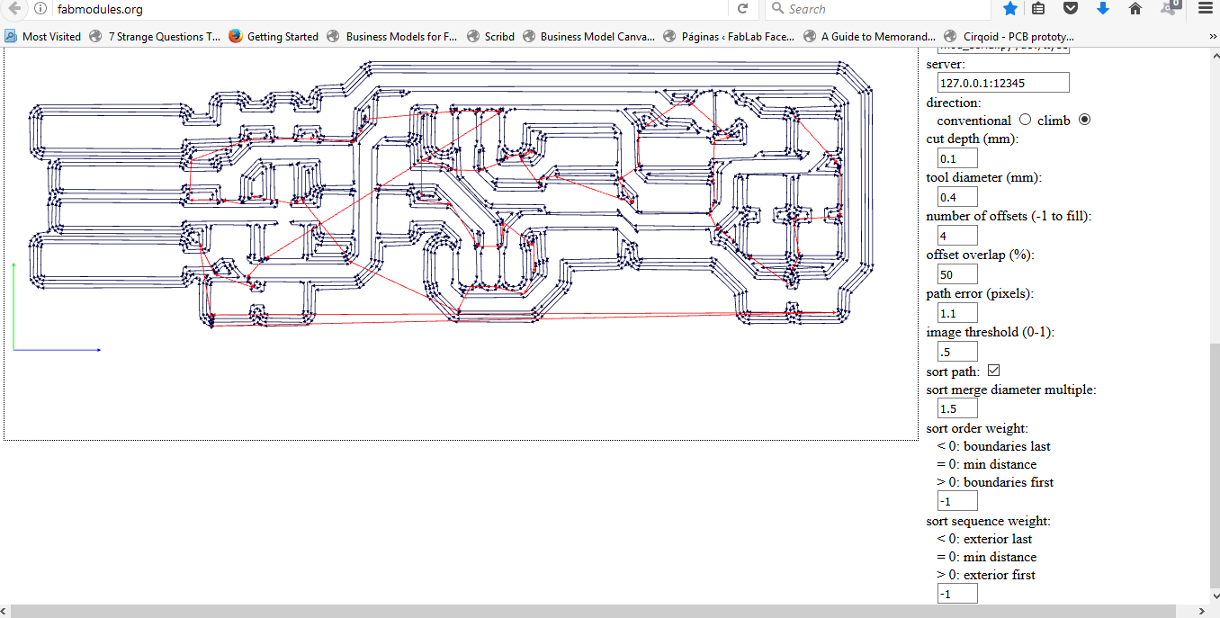
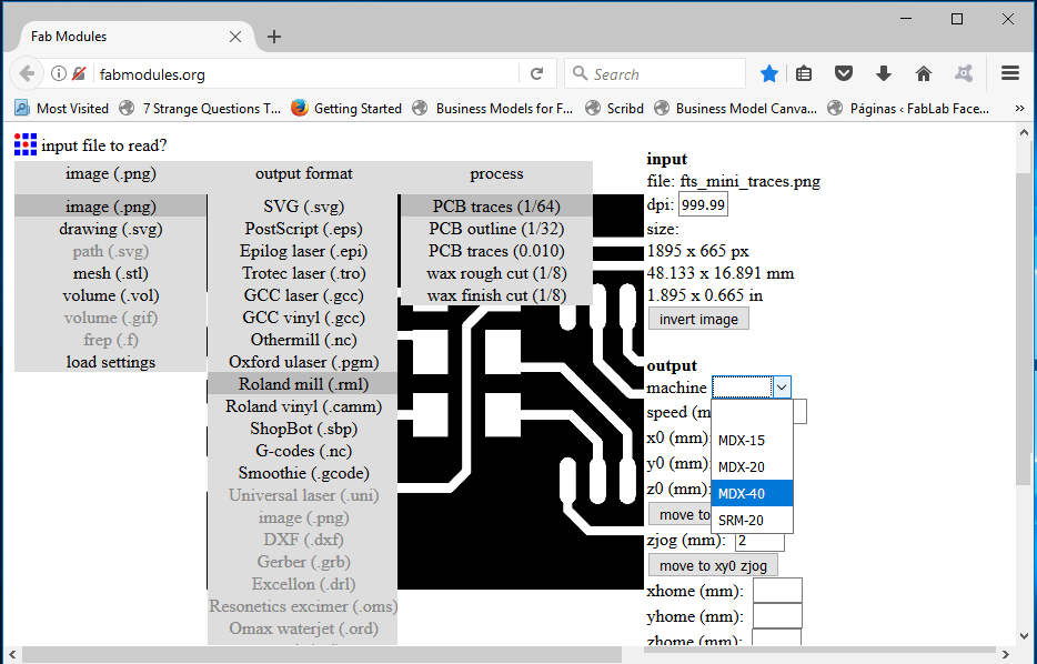
To genarate the codes for the Roland Machine I used the Fabmodules online version, the only settings that i changed was the "Endmill diameter" to 0.4mm and the "JOG" of the X, Y and Z Axis to 0
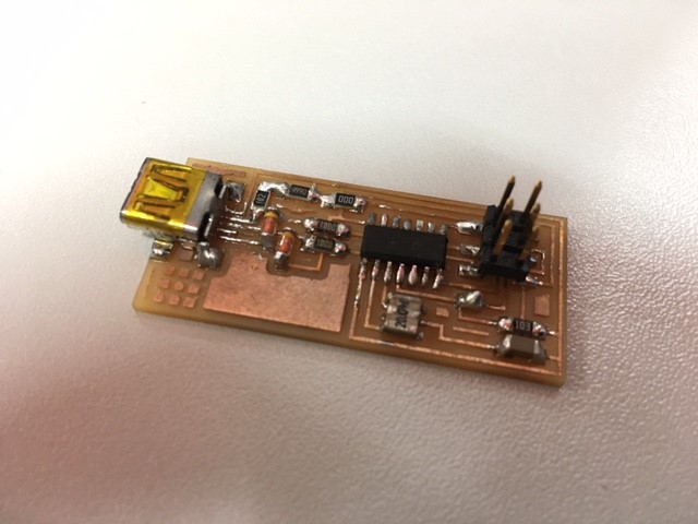
My final desing was ready and all the componets were in the right place and rigth oriented, this time I was didn't letr the solder tip for too long on the pcb and didn't have any problems this time
Download the firmware source code and extract the zip file Link to Firmware here
- update the Makefile for the type of programmer: usbtiny
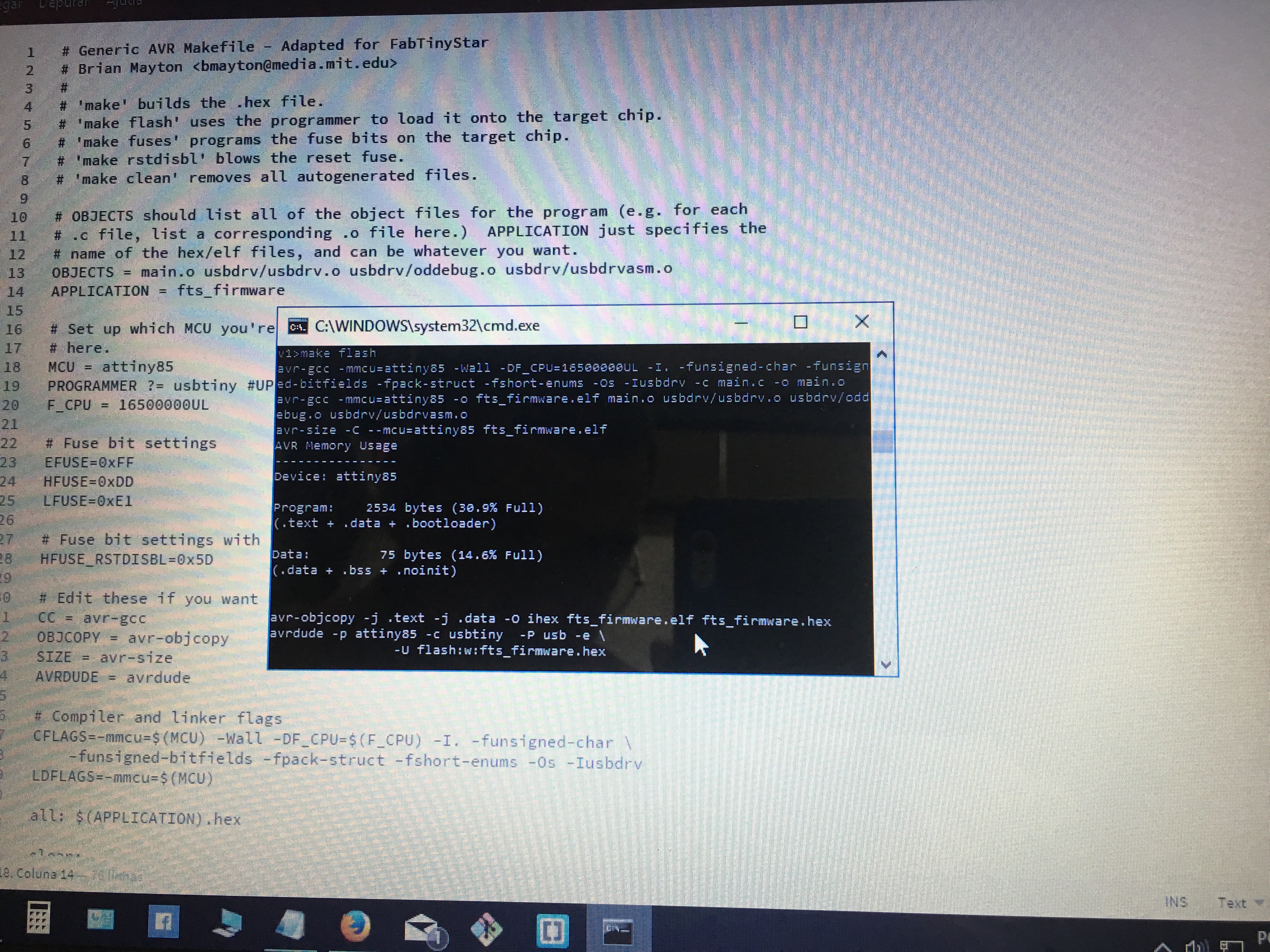
I used brackets to edit the makefile. Brackets is properly to edit web files, but it can also be used to edit programming files like the Makefile
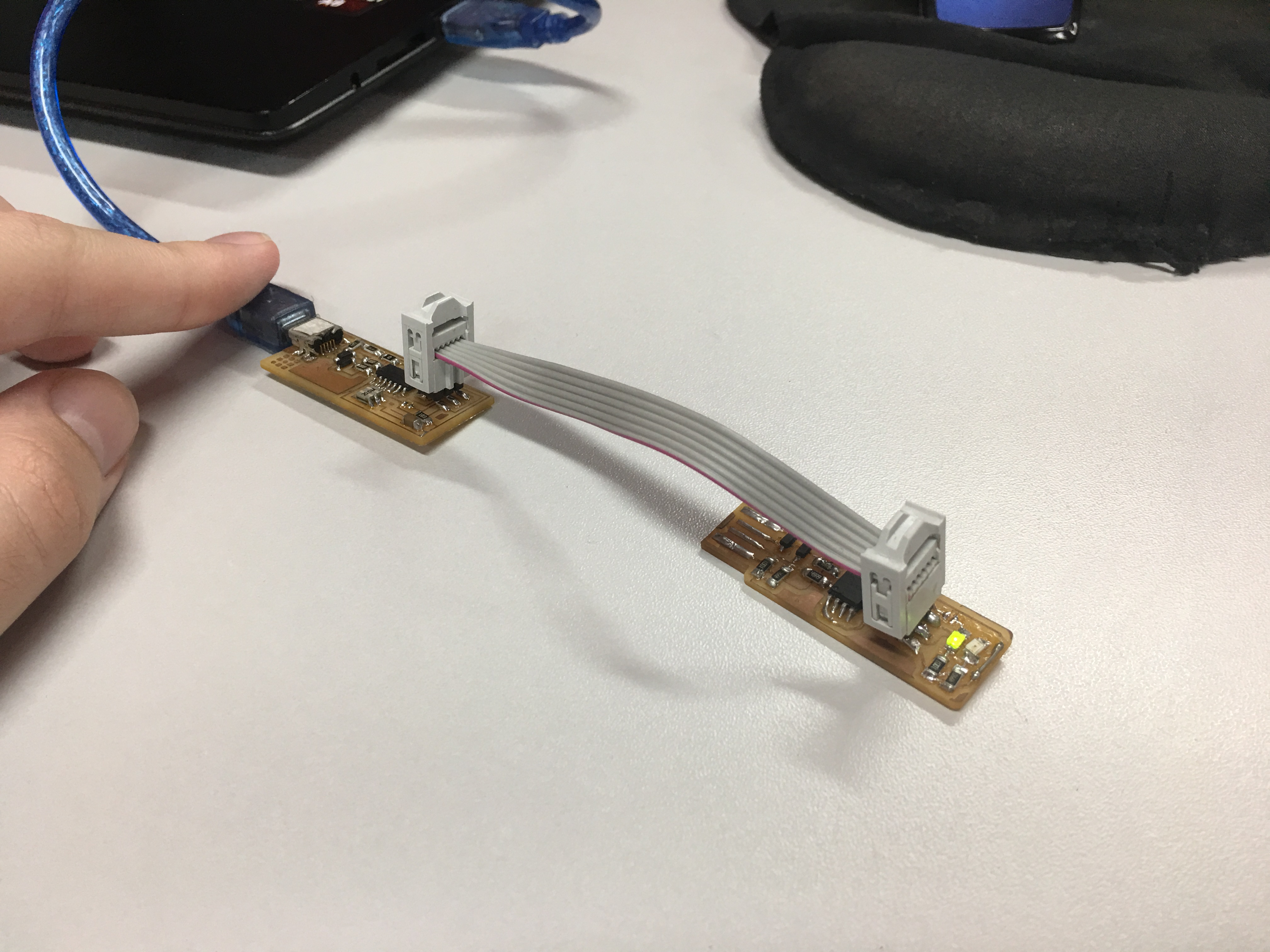
- Connect the programmer to the ISP header on your board.
-Run make flash. This will erase the target chip, and program its flash memory with the contents of the .hex file you built before.
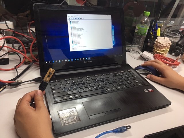
-Run the make fuses command. This will set up all of the fuses except the one that disables the reset pin. - This will allow us to check that the board works as a USB device, but it won't yet be able to program other boards.
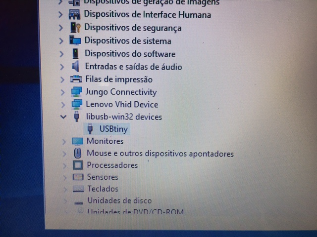
-Windows lists USB devices in Device Manager (Start → Control Panel → System → Device Manager)
-Connect your ISP programmer to your board one more time, and run make rstdisbl - This will let the chip use the reset pin to program other boards, but will disable the ability for this chip to be programmed again.
- disconnect VCC from the Vprog pin on the ISP header by removing the bridge on the solder jumper.