Assignment : producing the hello ISP 44 board
Milling Bit
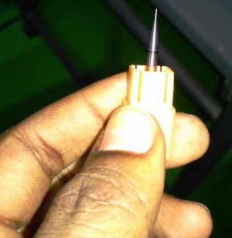
Milling bits are classifieds based on their diameter, ends and flutes. For creating FabISP, we would be using two drill bits. 1/64 in drilling bit is used to remove copper layer from board 1/32 in drilling bit is used to cut the board.
Things Required in Fab Lab
To create the board, the board layout can be designed using EAGLE.
For creating FabISP, we need the following things in FabLab
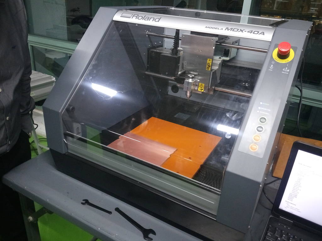
- Roland Modela MDX-40 Milling Machine
- A computer running Windows/Ubuntu/Macintosh
- FR-1 copper clad board
- Double sided tape
The Board
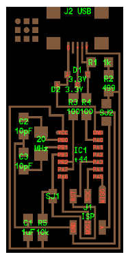
- Components marked with an "R" (R1, R2, etc) are resistors.
- Components marked with a "C" (C1, C2, etc) are capacitors.
- J2 USB is the mini USB header
- IC1 t44 is an ATTINY44A micro-controller. The little circle on the micro-controller that should be facing to the top left. This circle/dot can be viewed using a magnifying glass. If the micro-controller is placed upside down, the board will never work.
- The resistors and capacitors of this board do not have polarity.
Using the Fab Module to Mill the Board
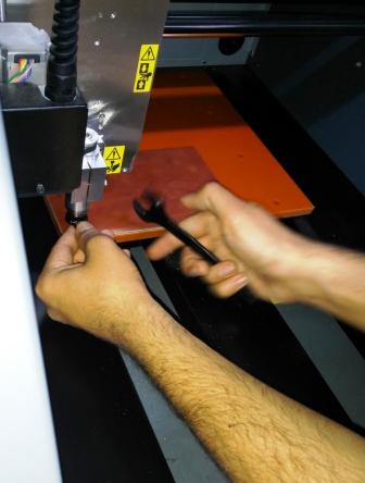
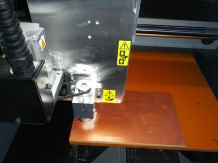
Fix the drill bit.
Drill bit can be inserted in the collet as shown & can be replaced by loosening the the grip using allen key. Here I am fixing 1/64 inch bit to do the milling part and then operate the machine further
Setting up the Origin
Origin can be set up by changing Xmin and Ymin values on the fab modules and clicking the move button.
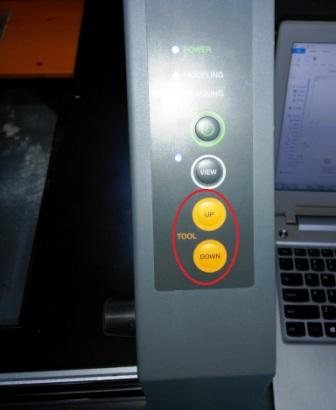
The z axis origin can be setup by moving down the milling bit by clicking the physical move (UP/DOWN) key on the machine. This has to be done carefully as it may break the drill bit if moved further down. The drilling bit can be loosened using allen key, allowed to drop on the board and once bit touches the surface of the board the drilling bit should be tightened again after it touches the surface of the board.
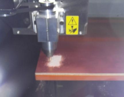
Placing the board on the machine bed
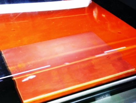
We used FR1 (Phenolic Paper) boards for the assignment. This board was fixed using the double side tape . The details of the same are given below: Double-sided tape is any pressure sensitive tape that is coated with adhesive on both sides. It is designed to stick two surfaces together, often in a way which is not visible in the end product, due to it being in between the objects rather than overlaying them.
This allows for neater-looking projects and better craftsmanship. Double-sided tape can be either thin or dimensional. Double-sided tape is created by applying a thin adhesive layer to each side of a carrier material. For example, double-sided tissue tape, an easy-to-rip double-sided tape, is created by applying adhesive to two sides of tissue paper, which is then wound with a silicone paper to avoid it sticking to itself. Most adhesive tapes are manufactured in log form, such as a large 1 to 3 meter wide roll, and then an adhesive tape converter is used to slit the rolls into the required widths.
Placing the board on the machine bed
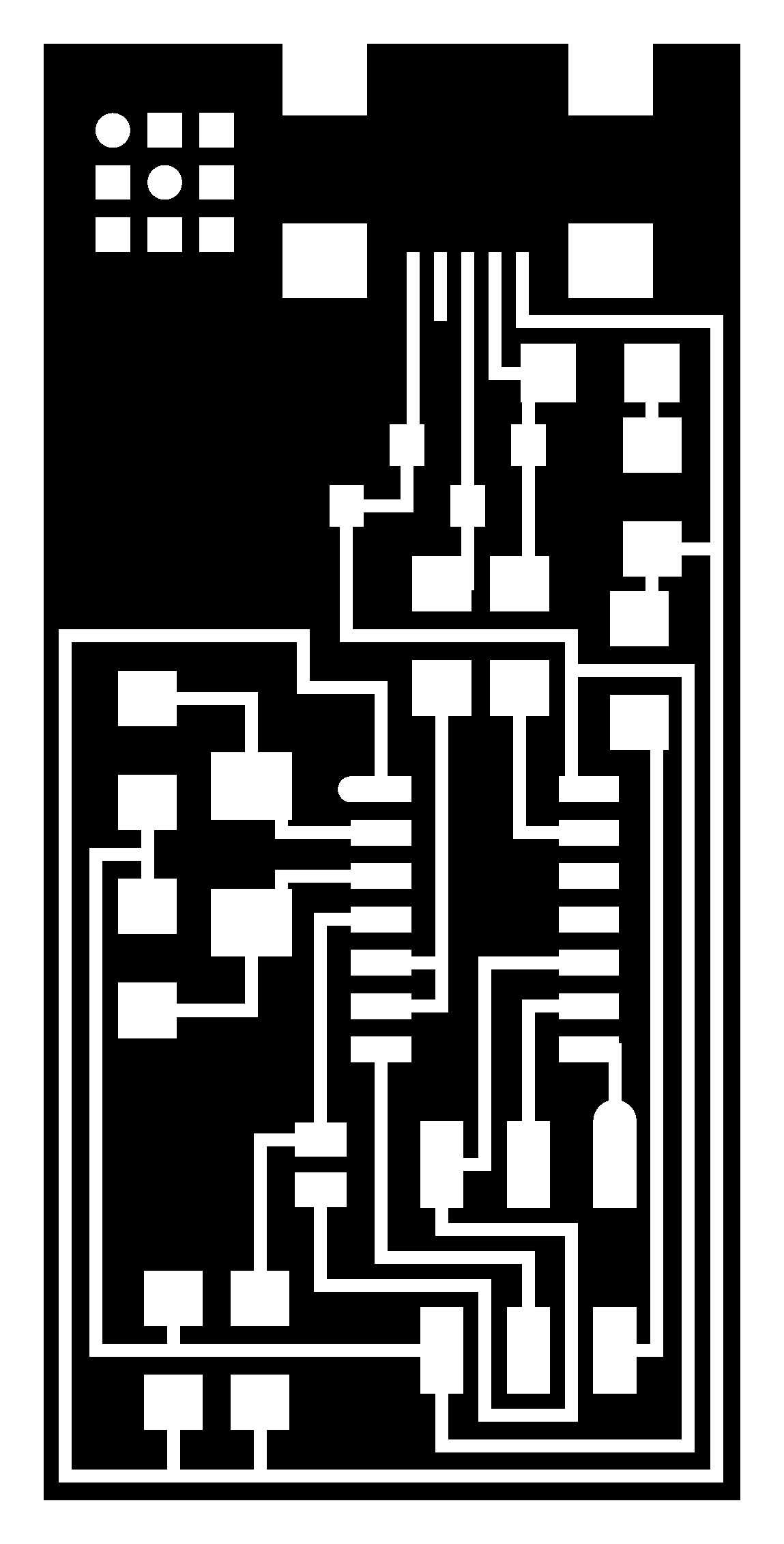
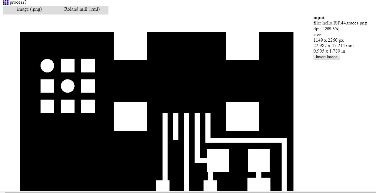
I used the Fab Module to download the .png image of the traces as shown
Then select the machine model Roland MDX-40 setup in our Lab Changed the speed to 2mm/s & zjog to 2mm. It is good to set the zjog at 2mm else there would be unwanted vibrations due to fast acceleration & deceleration of the cutter spindle
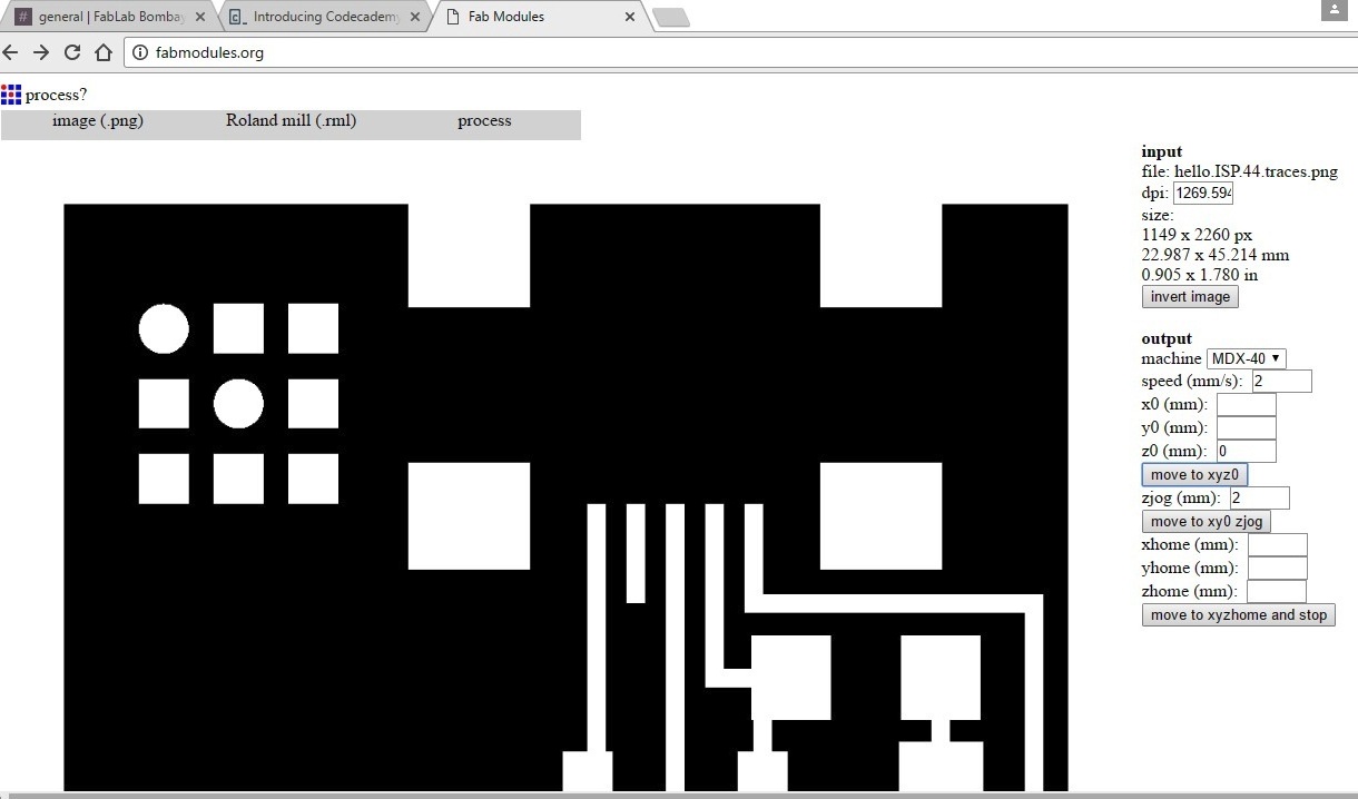
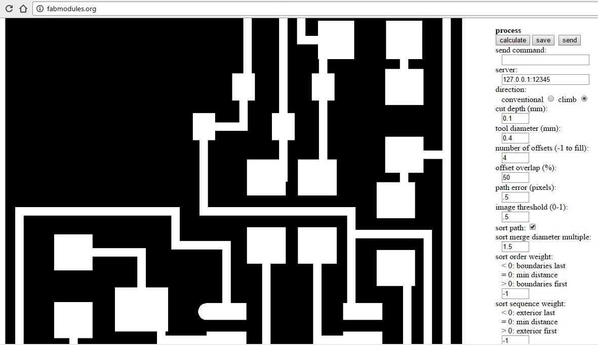
The cutter diameter used is 0.4mm and hence a cutting depth of 0.1mm was selected. All other parameters were used as set by default.
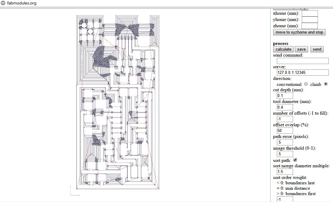
By clicking the calculate button the a simulation of the tool path is shown on the screen. Once the simulation finishes, save the mill file to be fed to the software of milling machine.
Once everything is setup, we need to click on "Make.rml" and the print order can be send to the machine by clicking "Send". The machine will right away start milling the board.
View button on the machine can be clicked to pause the operation and see the progress.
Cutting the Board
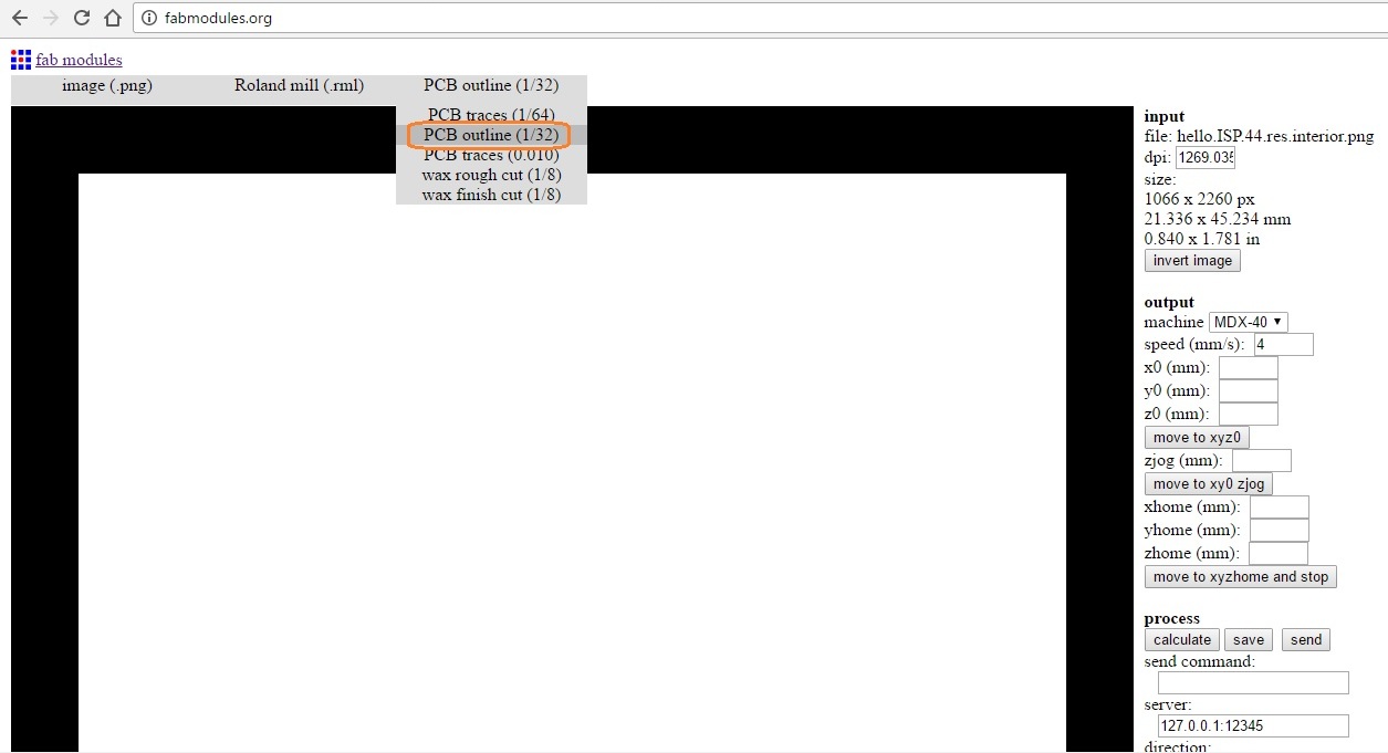
To cut the board from the main board, the drilling bit should be replace with allen key to 1/32 inch, load the cutting PNG which has only the boundary of the board as its trace and repeat the same procedure. On the Fab Modules, we should also change the option to "cutout board(1/32) from the drop-down option.
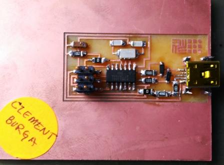
The board once cut looks something like this , except the 2 zero ohm resistors
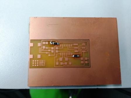
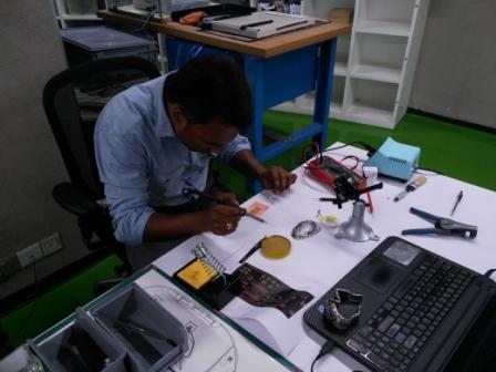
After that its only a matter of picking the right components and soldering it to the board using electronics workbench
Components Required
- ATTiny 44 micro-controller : 1
- Capacitor 1uF : 1
- Capacitor 10 pF : 2
- Resistor 100 ohm : 2
- Resistor 499 ohm : 1
- Resistor 1K ohm : 1
- 6 pin header : 1
- Resistor 10K : 1
- USB connector : 1
- Jumpers - 0
- ohm resistors : 2
- Cystal 20MHz Zenor Diode 3.3V : 2
- USB mini cable : 1
- Ribbon cable : 1
- 6 pin connector : 2
Problems Faced
I was doing soldering for the first time and was quiet excited to do it. Though it was the first time I was going to do it , but I had seen my friends do it. Along with learning the process of soldering I had to also ensure hat I don’t damage the board by laying the molten solder between traces.
At start I was avoiding the use of flux/wax. Later realized that applying wax helps the solder to hold it properly. But at the same time if while applying flux, if it is applied in between traces then the solder would even spread there. So ensure to apply little flux at the right places.
I soldered all the resistors & capacitors first & then later took up to solder the mini USB. Since the mini USB traces are very tiny it was very difficult to solder using the regular solder gun. Even after using a pointed solder gun it was difficult to reach the tiny area to solder. Hence found a method to solder the USB traces.
Method to solder mini USB
Disintegrate the molten solder into tiny pieces as the size of the traces and then apply it so that it wont spread to the neighboring trace.
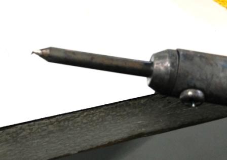
Image Before USB soldering is complete
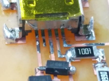
Image After USB soldering is complete
The HEllo ISP 44 is ready.
learnings of this week
- Roland MDX - 40 learnt to operate this milling machine for the many boards that I will be milling for making many of the circuit boards.
- Fab modules to set the parameters for cutting the PCB board.
- Soldering the PCB board with all the tiny elements was entirely a different experience for me.
Files to download

This work is licensed under a Creative Commons Attribution-NonCommercial-ShareAlike 4.0 International License.