AVR - ATtiny 44 Micro-controller
A micro-controller is a small computer (SoC) on a single integrated circuit containing a processor core, memory, and programmable input/output peripherals. Program memory in the form of Ferroelectric RAM, NOR flash or OTP ROM is also often included on chip, as well as a typically small amount of RAM
The documentation for Atmel’s ATtiny44 MCU is a whopping 268 page pdf. Electronics was never my cup of tea. But I had to go through the data sheet to understand what the micro-controller is capable of doing & how it does.
Some of the features of the ATtiny 44 are as listed below:
- High Performance, Low Power AVR 8-bit Micro-controller
- 120 Powerful Instructions – Most Single Clock Cycle Execution
- 256/512 Bytes of In-System Programmable EEPROM
- Data Retention: 20 years at 85°C / 100 years at 25°C
- In-System Re-programmable Flash memory for program storage.
- Programmable Brown-out Detection Circuit with Software Disable Function
- Operating Voltage: – 1.8 – 5.5V
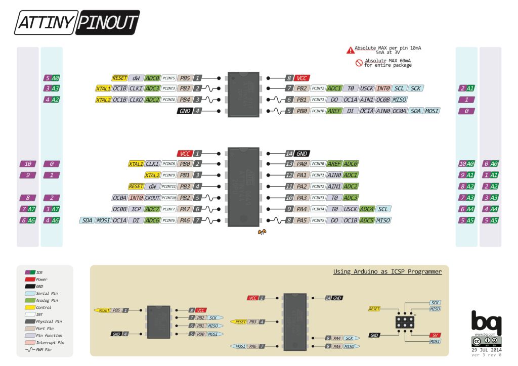
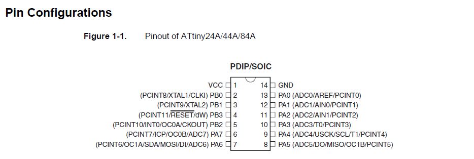
The Pin Configuration and Pin Descriptions in Section 1 are important - PighiXXX has created very nice color-coded pin-out diagrams for many processors including the ATtiny family, including pin mapping for the Arduino IDE:
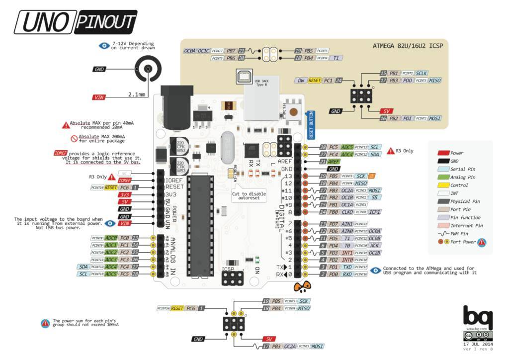
The image below will show the AURDUINO UNO Pin Out which was very useful for me to understand how to connect the the Arduino with the physical board I design.
Pin Configurations
Preparing the board
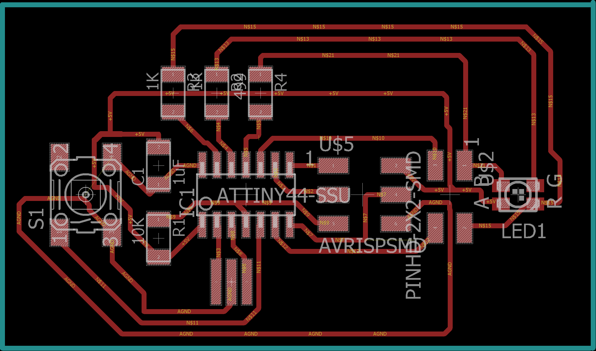
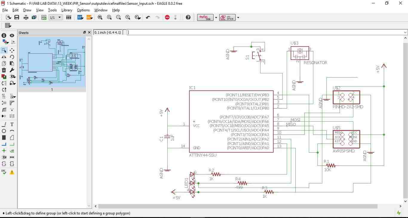
After understanding the ATtiny 44 then I prepared the schematic of the circuit using Eagle. The below images depict the schematic & the board.
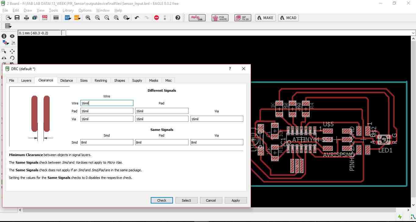
Then switch the tab to board & placing all the elements of the board to my satisfaction, For making the board I used the Auto routing option with the traces thickness 0.4mm an all the clearances kept at 16mill. Then I did the "DRC" check as shown in the below image.
Some times the auto routing option keeps the traces thickness at 0.25mm which is not desirable for board milling. Hence it is always recommended to check the thickens of the traces by converting the board to .dxf format in AutoCAD as shown in th below image.
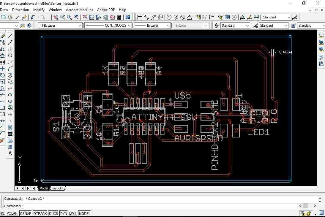
Once everything is ensured export the board to .png format for milling.
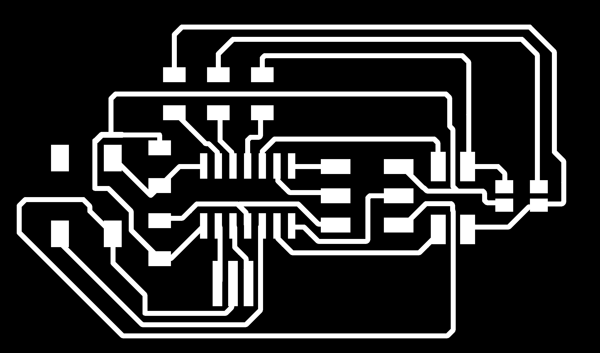
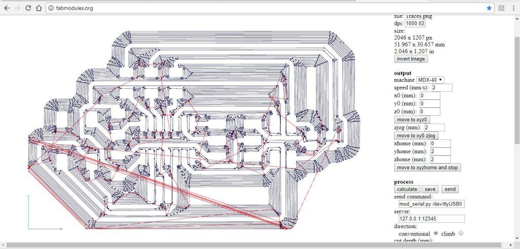
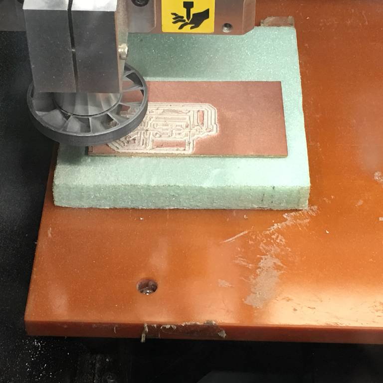
The below image shows the traces in the fab module using MDX-40 milling machine
my study of Ultrasonic HC-sr04 sensor
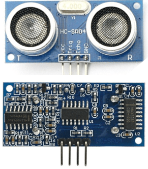
The HC-SR04 ultrasonic sensor uses sonar to determine distance to an object like bats do. It offers excellent non-contact range detection with high accuracy and stable readings in an easy-to-use package. From 2cm to 400 cm or 1” to 13 feet. It operation is not affected by sunlight or black material like Sharp range finders are (although acoustically soft materials like cloth can be difficult to detect). It comes complete with ultrasonic transmitter and receiver module.
There are only four pins that you need to worry about on the HC-SR04: VCC (Power), Trig (Trigger), Echo (Receive), and GND (Ground). You will find this sensor very easy to set up and use for your next range-finding project! . The complete data sheet of this sensor can be found in this link.
HC-SR04 Data Sheet. I have explored a little bit more & found another good tutorial where in the details of this sensor explained in easy way to understand. Tutorial.
Programing the board for Input device
The functioning of the board includes to write a C-Program & also use the Gestalt x-y node given by Neil.
First I need to make the Arduino as an ISP by following the steps below.
First I connected the Arduino board to my computer. I will make the Arduino board as a programmer to program my Board. Doing the following steps as seen in the below pics:
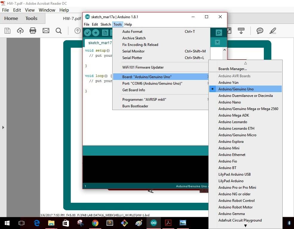
Step 1: In Tools ------- Board-------select "Arduino/Genuino Uno"--------
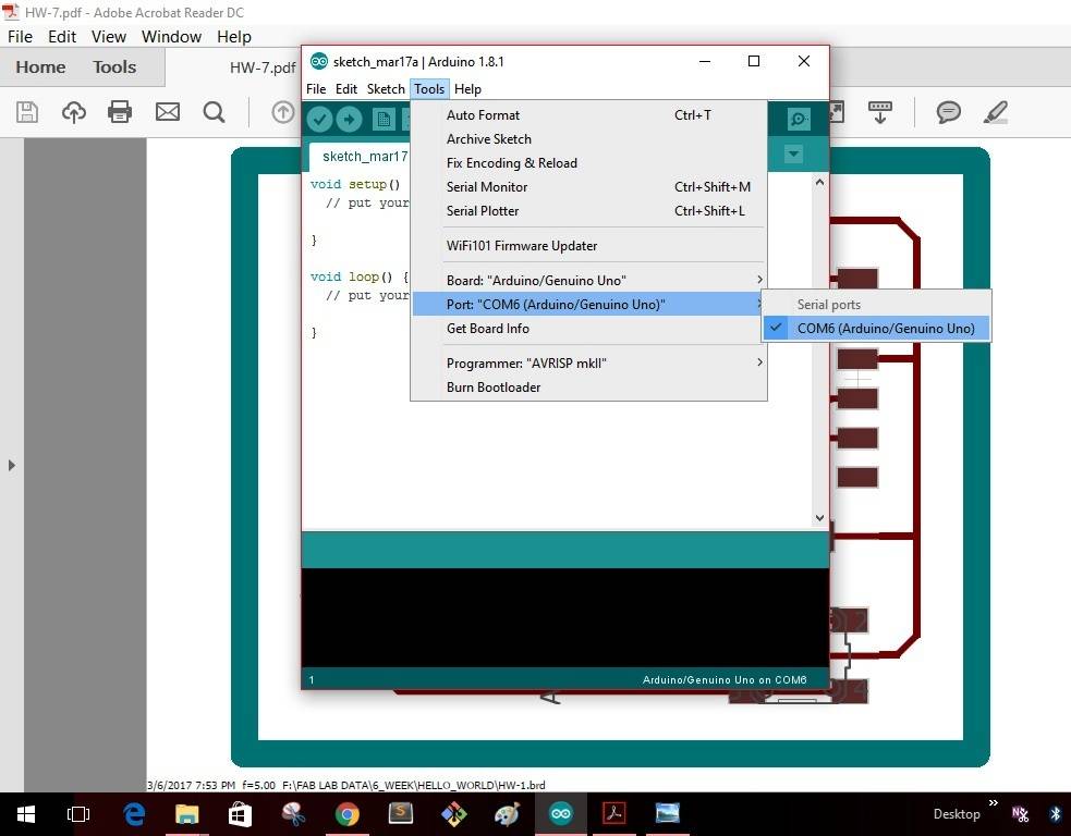
Step 2: In Tools ------- Port-------select "COM6(Arduino/Genuino Uno")--------
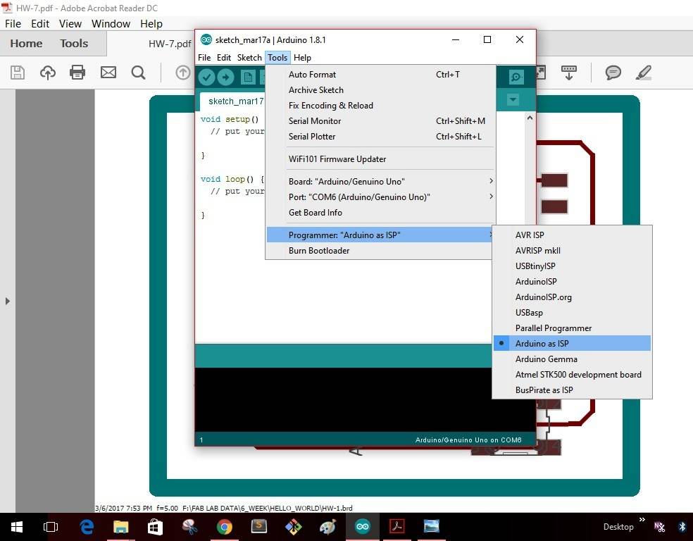
Step 3: In Tools -------Programmer-------select "Arduino as ISP"--------
Step 4: In File -------Examples-------select "Arduino ISP"--------
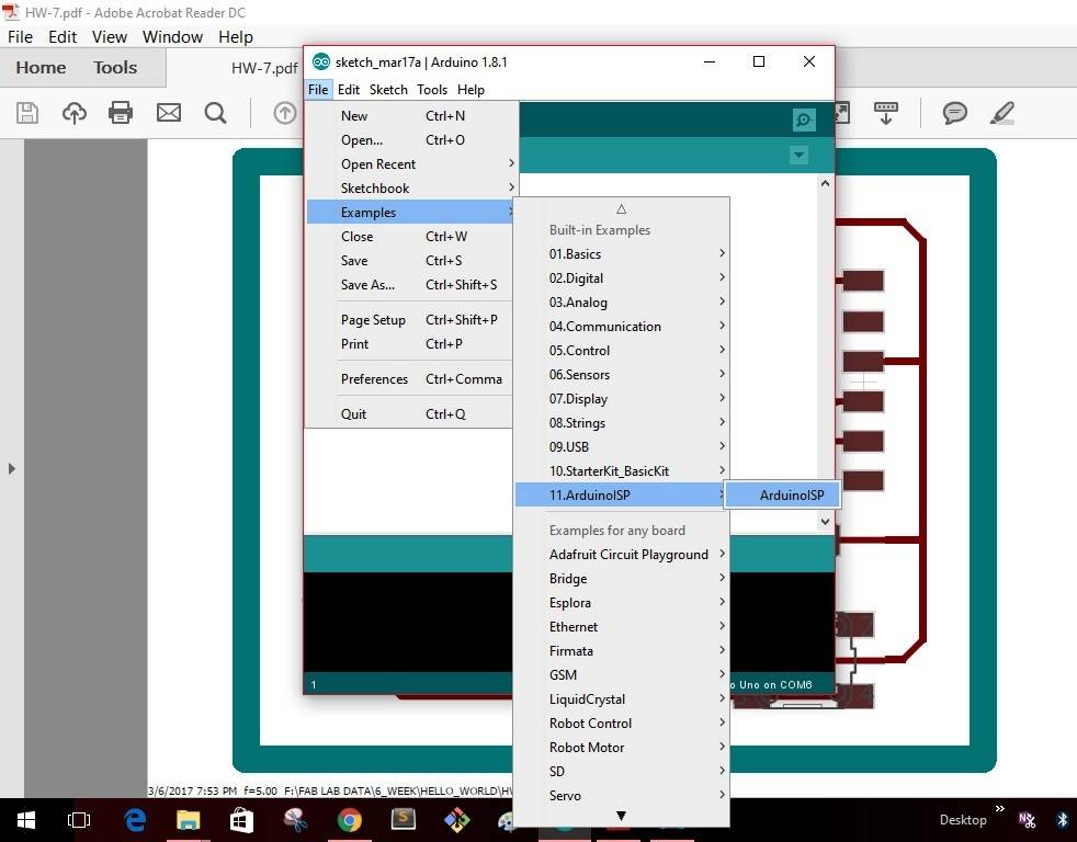
Step 5: As soon as I select the "Arduino ISP" the window as shown will pop up with a yellow icon as shown. Click the icon to upload the program into the Arduino board.
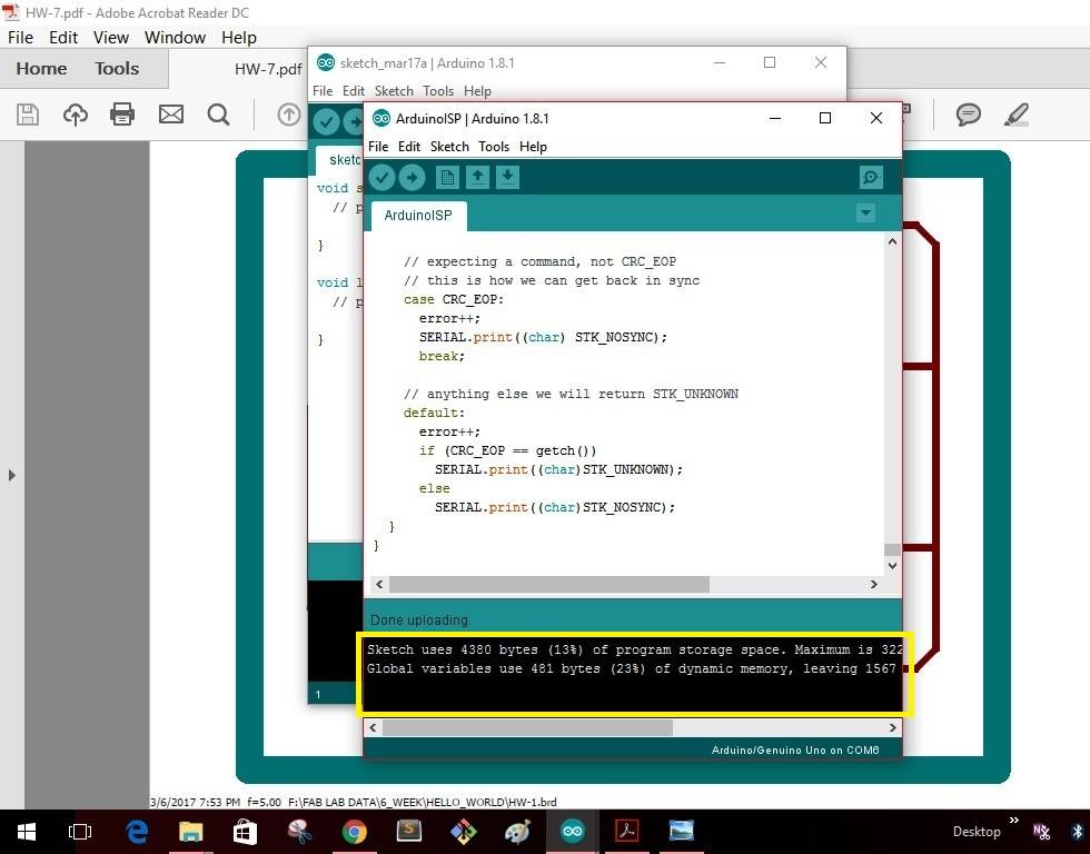
Once the uploading gets completed the window as shown below will give as message that uploading is completed.
This completes making the "Arduino" board as a programmer. I disconnect the board with my computer
Programing the board will be suitable to the circuit I have designed. I have gone through a tutorial in "wwww.howtomechatronics.com & modified my code to suit my application. The link for the tutorial can be followed at Tutorial . The code which I have written is derived from this code which can be followed here Example Code . Then I coded the Arduino IDE board to which the sensor HC-SR04 is connected. I have done this to test the sensor module for its working. The code for testing can be seen below.
unsigned long echo = 0;
int ultraSoundSignal = 9; // Ultrasound signal pin
unsigned long ultrasoundValue = 0;

void setup()
{
  Serial.begin(9600);
  pinMode(ultraSoundSignal,OUTPUT);
}

unsigned long ping()
{
  pinMode(ultraSoundSignal, OUTPUT); // Switch signalpin to output
  digitalWrite(ultraSoundSignal, LOW); // Send low pulse
  delayMicroseconds(2); // Wait for 2 microseconds
  digitalWrite(ultraSoundSignal, HIGH); // Send high pulse
  delayMicroseconds(5); // Wait for 5 microseconds
  digitalWrite(ultraSoundSignal, LOW); // Holdoff
  pinMode(ultraSoundSignal, INPUT); // Switch signalpin to input
  digitalWrite(ultraSoundSignal, HIGH); // Turn on pullup resistor
  // please note that pulseIn has a 1sec timeout, which may
  // not be desirable. Depending on your sensor specs, you
  // can likely bound the time like this -- marcmerlin
  // echo = pulseIn(ultraSoundSignal, HIGH, 38000)
  echo = pulseIn(ultraSoundSignal, HIGH, 38000); //Listen for echo
  ultrasoundValue = (echo / 58.138) * .39; //convert to CM then to inches
  return ultrasoundValue;
}

void loop()
{
  int x = 0;
  x = ping();
  Serial.println(x);
  delay(250); //delay 1/4 seconds.
}
The next thing was I modified the code to include a LED connected to PIN13, and then coded the board in such a way that the LED turns ON when the distance is more than 25cm. I have done this to check the functionality before programming the board that I have made.
The purpose of doing this step is to ensure that the LED on the board which I designed glows when the object is sensed by the sensor. This will be an output measure for the working of the sensor. The code used can be seen below
//Program that ONs the LED on Pin 13 when the distance in Ultrasonic Sensor HC-04 becomes less than 25 cm.
//Ref: Blink Example, http://howtomechatronics.com/tutorials/arduino/ultrasonic-sensor-hc-sr04/ , https://www.arduino.cc/en/reference/else

// defines pins numbers
const int trigPin = 9;
const int echoPin = 10;
const int ledPin = 13;
// defines variables
long duration;
int distance;


// the setup function runs once when you press reset or power the board
void setup() {

pinMode(ledPin, OUTPUT); // Sets the ledPin as an Output
pinMode(trigPin, OUTPUT); // Sets the trigPin as an Output
pinMode(echoPin, INPUT); // Sets the echoPin as an Input
Serial.begin(9600); // Starts the serial communication
}

// the loop function runs over and over again forever
void loop() {

// Clears the trigPin in the ultrasonic sensor
digitalWrite(trigPin, LOW);
delayMicroseconds(2);
// Sets the trigPin on HIGH state for 10 micro seconds
digitalWrite(trigPin, HIGH);
delayMicroseconds(10);
digitalWrite(trigPin, LOW);
// Reads the echoPin, returns the sound wave travel time in microseconds
duration = pulseIn(echoPin, HIGH);
// Calculating the distance
distance= duration*0.034/2;
//distance= duration;
// Prints the distance on the Serial Monitor
Serial.print("Distance: ");
Serial.println(distance);

if (distance>25)
  {digitalWrite(ledPin, HIGH);  // turn the LED on (HIGH is the voltage level)
  delay(1000);   }              // wait for a second
  else
  {digitalWrite(ledPin, LOW);   // turn the LED off by making the voltage LOW
  delay(1000);}                 // wait for a second

}
Then finally I programmed the micro-controller Attiny44 using the Arduino IDE. I have included a RGB LED with 2 spare pins on the board. I connected the HC-SR04 and this time did the programming to turn ON the RGB LED when the disance is less than 25cm. The proximation of the sensor can used as a feature of this sensor. The code for this can be seen below.
//Program that ONs the LED on Pin 13 when the distance in Ultrasonic Sensor HC-04 becomes less then 25 cm.
//Ref: Blink Example, http://howtomechatronics.com/tutorials/arduino/ultrasonic-sensor-hc-sr04/ , https://www.arduino.cc/en/reference/else

// defines pins numbers
const int trigPin = 3;
const int echoPin = 7;
const int ledPin = 0;

//define RGB LED pin numbers
int redPin= 0;
int greenPin = 2;
int bluePin = 1;

// defines variables
long duration;
int distance;

// the setup function runs once when you press reset or power the board
void setup() {

pinMode(ledPin, OUTPUT); // Sets the ledPin as an Output
pinMode(trigPin, OUTPUT); // Sets the trigPin as an Output
pinMode(echoPin, INPUT); // Sets the echoPin as an Input

pinMode(redPin, OUTPUT);
pinMode(greenPin, OUTPUT);
pinMode(bluePin, OUTPUT);

//Serial.begin(9600); // Starts the serial communication
}

// the loop function runs over and over again forever
void loop() {

// Clears the trigPin in the ultrasonic sensor
digitalWrite(trigPin, LOW);
delayMicroseconds(2);
// Sets the trigPin on HIGH state for 10 micro seconds
digitalWrite(trigPin, HIGH);
delayMicroseconds(10);
digitalWrite(trigPin, LOW);
// Reads the echoPin, returns the sound wave travel time in microseconds
duration = pulseIn(echoPin, HIGH);
// Calculating the distance
distance= duration*0.034/2;
//distance= duration;
// Prints the distance on the Serial Monitor
//Serial.print("Distance: ");
//Serial.println(distance);
setColor(255, 255, 255);
delay (1000);
setColor(0, 0, 0);
delay (1000);
if (distance>25)
setColor(255, 255, 255); // RGB
else
setColor(0, 0, 0);

}

void setColor(int redValue, int greenValue, int blueValue) {
//  analogWrite(redPin, redValue);
//  analogWrite(greenPin, greenValue);
  analogWrite(bluePin, blueValue);
}
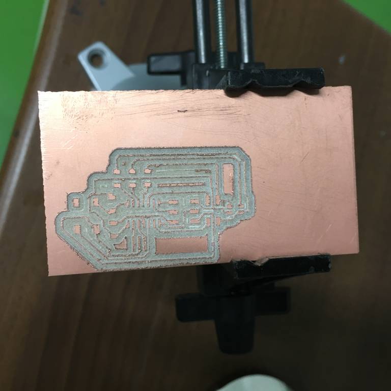
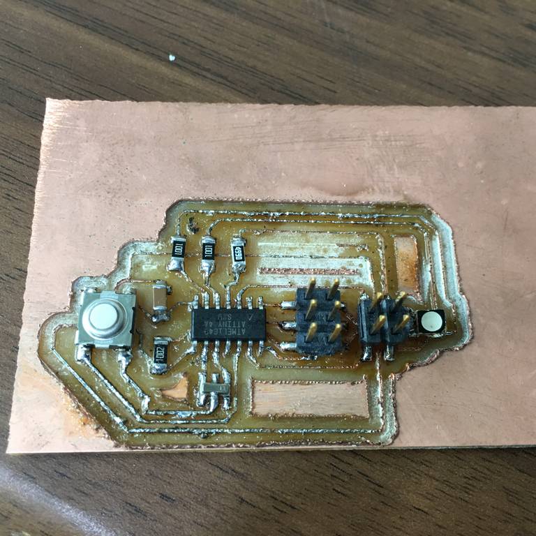
The image shows the board in milling process & after milling is complete before stuffing
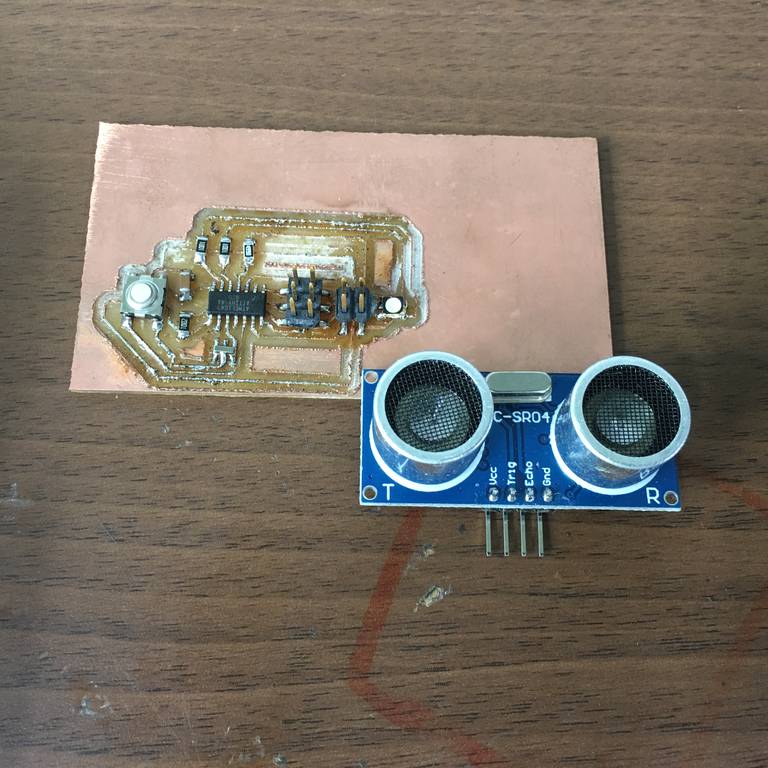
The image shows the board after stuffing & along with the Sensor
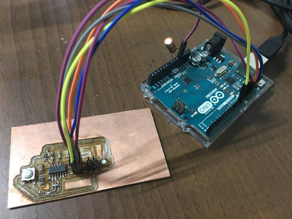
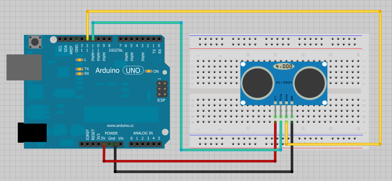
The next step is to connect the board with all the elements to check the working of the board with the program written into the micro-controller.The connections of the Arduino board with my board is shown in the image. I burnt the codes into the micro-controller to check that the LED is working. Finally I burnt the program in which, when an object is at a distance less than 25mm from the sensor the LED will glow.
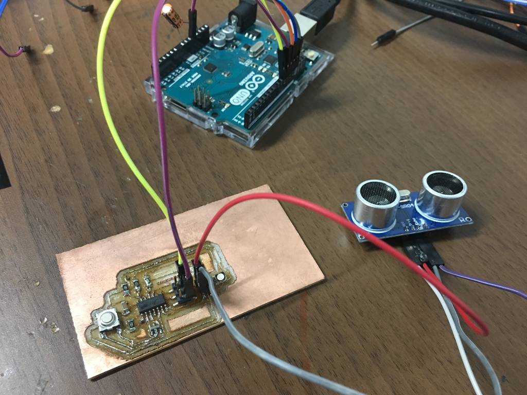
Then image shows the connections of the sensor with the board. I gave external 5 volt supply to the sensor.
Final working video
After burning the program to the micro-controller the final working of the sensor is shown in the video.
INPUT_DEVICE from Clement Burga on Vimeo.
Files to download

This work is licensed under a Creative Commons Attribution-NonCommercial-ShareAlike 4.0 International License.