Assignment : Networking & Communicate between 2 Boards
AVR - ATtiny 45 Micro-controller
A micro-controller is a small computer (SoC) on a single integrated circuit containing a processor core, memory, and programmable input/output peripherals. Program memory in the form of Ferroelectric RAM, NOR flash or OTP ROM is also often included on chip, as well as a typically small amount of RAM
The documentation for Atmel’s ATtiny45 MCU is a whopping 234 page pdf. Electronics was never my cup of tea. But I had to go through the data sheet to understand what the micro-controller is capable of doing & how it does.
Some of the features of the ATtiny 45 are as listed below:
- High Performance, Low Power AVR 8-bit Micro-controller
- 120 Powerful Instructions – Most Single Clock Cycle Execution
- 256/512 Bytes of In-System Programmable EEPROM
- Data Retention: 20 years at 85°C / 100 years at 25°C
- In-System Re-programmable Flash memory for program storage.
- Programmable Brown-out Detection Circuit with Software Disable Function
- Operating Voltage: – 1.8 – 5.5V
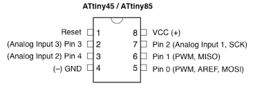
The Pin Configuration and Pin Descriptions in Section 1 are important - PighiXXX has created very nice color-coded pin-out diagrams for many processors including the ATtiny family, including pin mapping for the Arduino IDE:
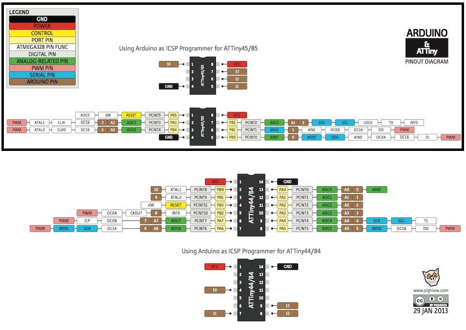
Pin Configurations
Preparing the Boards for networking & Communication
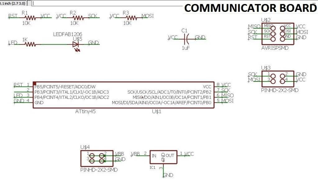
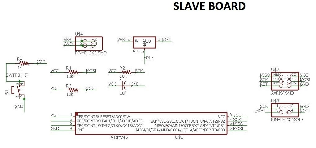
After understanding the ATtiny 45 then I prepared the schematic of the circuits of both the Communicator board & the slave board using Eagle. The below images depict the schematic of both the boards.
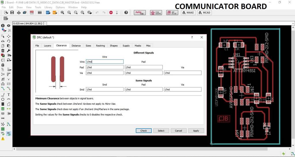
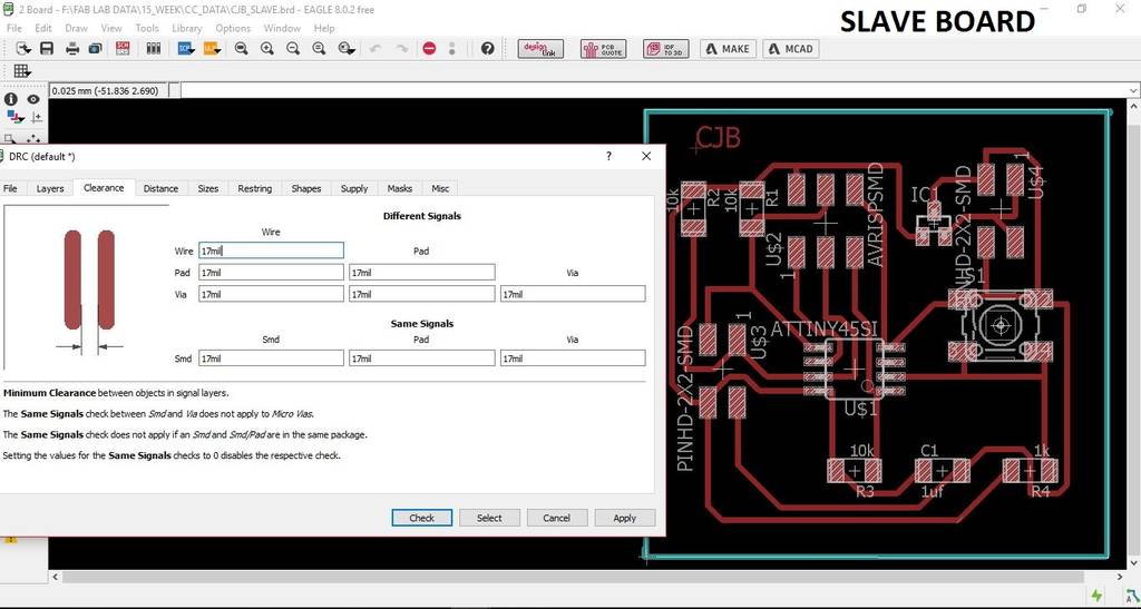
Then switch the tab to board & placing all the elements of the board to my satisfaction, For making the board I used the Auto routing option with the traces thickness 0.5mm an all the clearances kept at 0.4mill. Then I did the "DRC" check as shown in the below image.
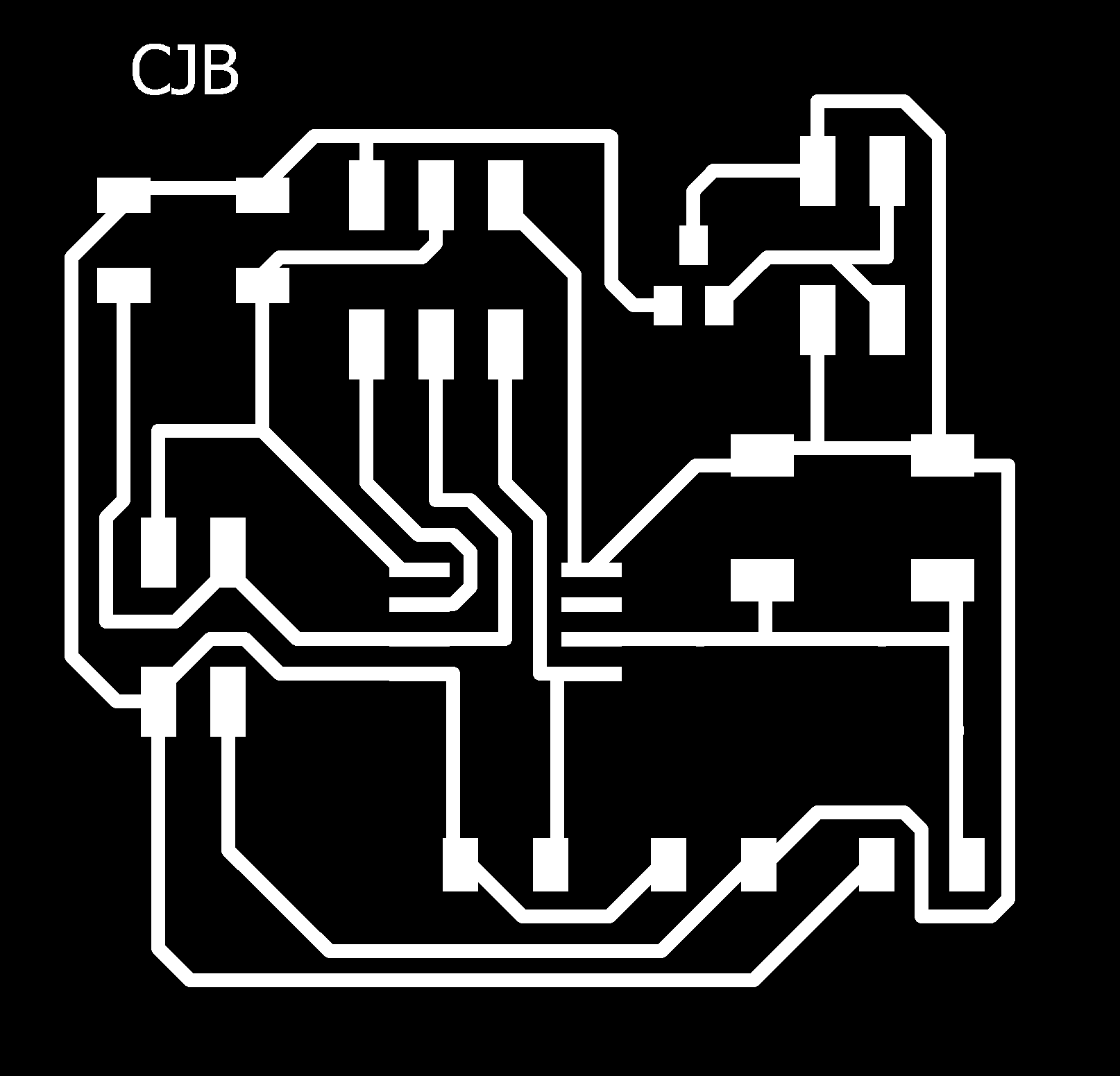
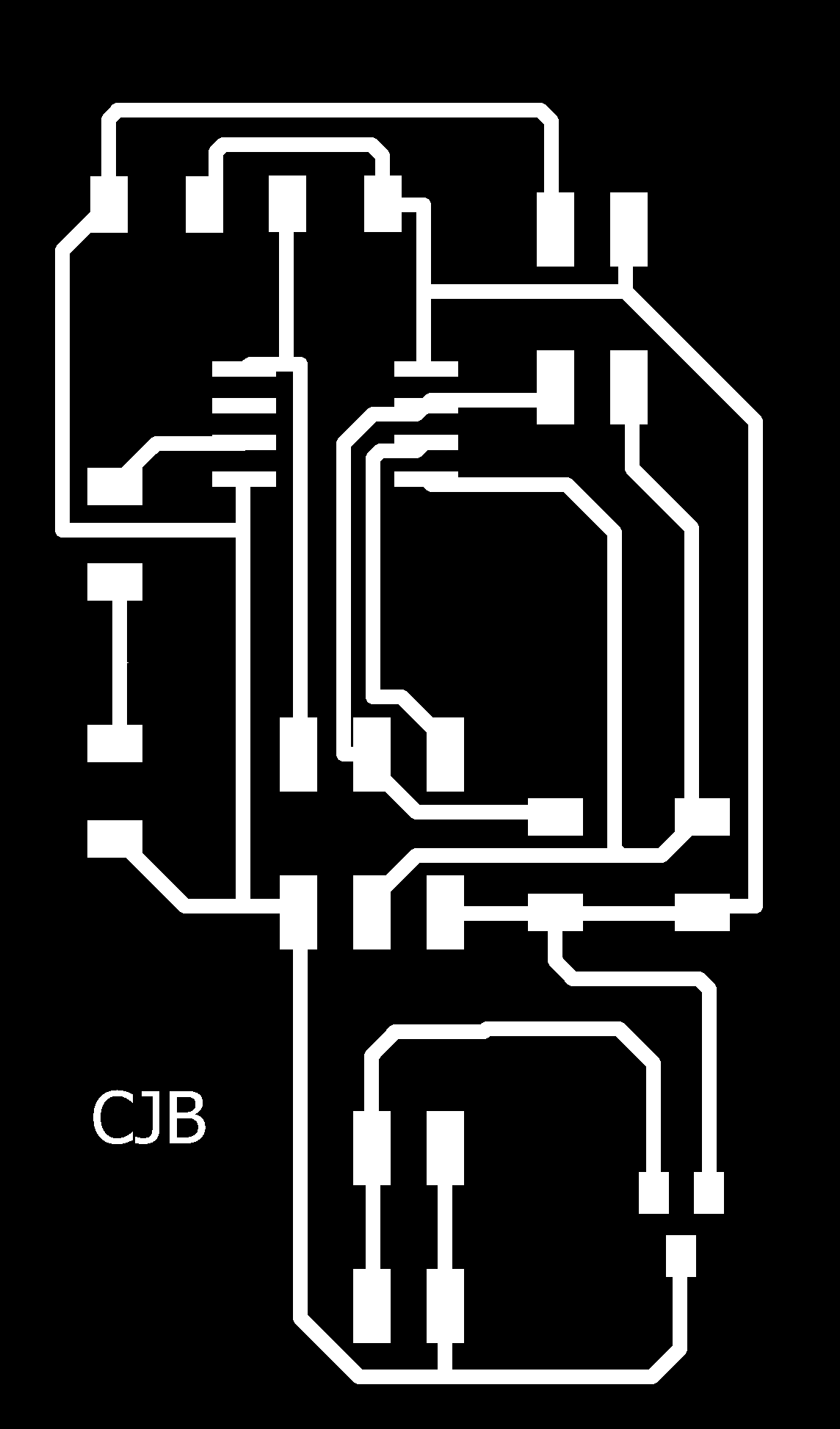
Then after the DRC check is done with no errors, export the traces & the outline into .png format to export this image to create the "rml" code using Fab Modules. Below images show the traces & the outline of both the boards.


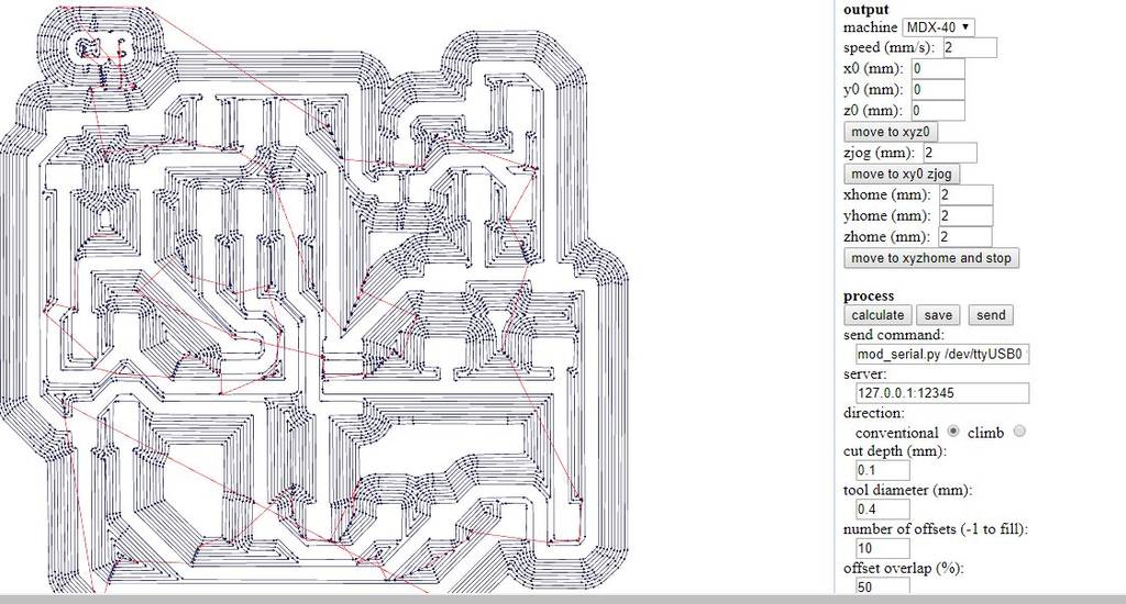
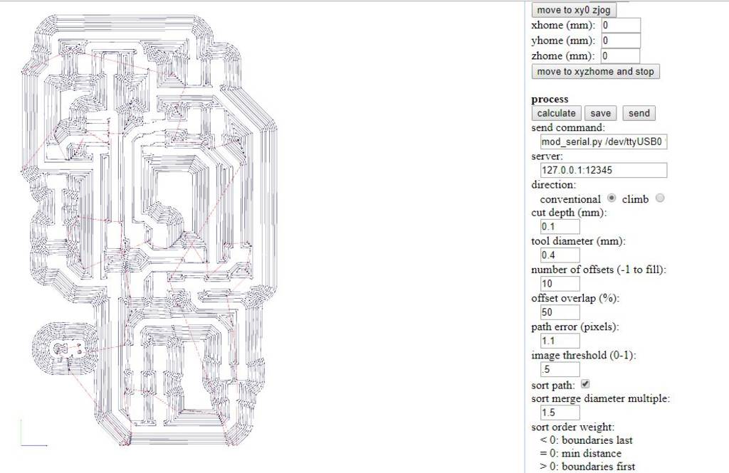
Import the .png files of the traces & the outline of both the boards into Fab Modules to generate the ".rml" code which will be used for milling of the boards on the MDX-40 machine. The below images show the rml code generated using Fab Modules.
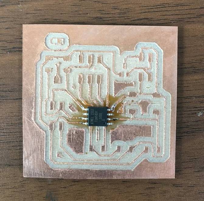
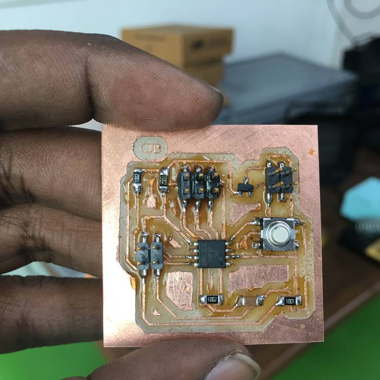
The below images show the board after milling is completed, before stuffing.
Programing the Boards for networking & Communication
Whilst the boards are being milled on the machine I was preparing the program for both the communicator board & the slave board. I wrote the code using Arduino. The below images show both the boards after stuffing all the elements.
Find below the Arduino Code for the Communicator Board
#include "TinyWireM.h"

#define device (1)
int ledPin = 4;

void setup() {
// put your setup code here, to run once:
pinMode(ledPin, OUTPUT);
TinyWireM.begin();
delay(1000);
}
void loop() {
if(IsSwitchPressed(0x1)==1)
{
digitalWrite(ledPin, LOW);
}
else if(IsSwitchPressed(0x1)==0)
{
digitalWrite(ledPin, HIGH);
}
}

int IsSwitchPressed(uint8_t slaveAddress){
int Output = 0;
TinyWireM.beginTransmission(slaveAddress);
TinyWireM.requestFrom(slaveAddress, 1);
Output = TinyWireM.receive();
return Output;
}
Find below the Arduino Code for the Slave Board
const int buttonPin = 3;
int switchcondition;
int buttonState = 0;
#define I2C_SLAVE_ADDRESS 0x1

#include "TinyWireS.h"

#ifndef TWI_RX_BUFFER_SIZE
#define TWI_RX_BUFFER_SIZE ( 16 )
#endif

volatile uint8_t i2c_regs[] =
{
    0xDE,
    0xAD,
    0xBE,
    0xEF,
};
volatile byte reg_position;
const byte reg_size = sizeof(i2c_regs);
void requestEvent()
{
    TinyWireS.send(CheckSwitchCondition());
    // Increment the reg position on each read, and loop back to zero
    /*
    reg_position++;
    if (reg_position >= reg_size)
    {
        reg_position = 0;
    }*/
}
void setup() {
  // put your setup code here, to run once:
  pinMode(buttonPin, INPUT); // Sets the buttonPin as an Input
  TinyWireS.begin(I2C_SLAVE_ADDRESS);
  TinyWireS.onRequest(requestEvent);
}
void loop() {
  // put your main code here, to run repeatedly:

  TinyWireS_stop_check();
}
int CheckSwitchCondition(){
  buttonState = digitalRead(buttonPin);
  if (buttonState == HIGH)
  {
    switchcondition=1;
  }
  else
  {
   switchcondition=0;
  }
  return switchcondition;
}
First I connected the Arduino board to my computer. I will make the Arduino board as a programmer to program my Hello World Board. Doing the following steps as seen in the below pics:
Step 1: In Tools ------- Board-------select "Arduino/Genuino Uno"--------
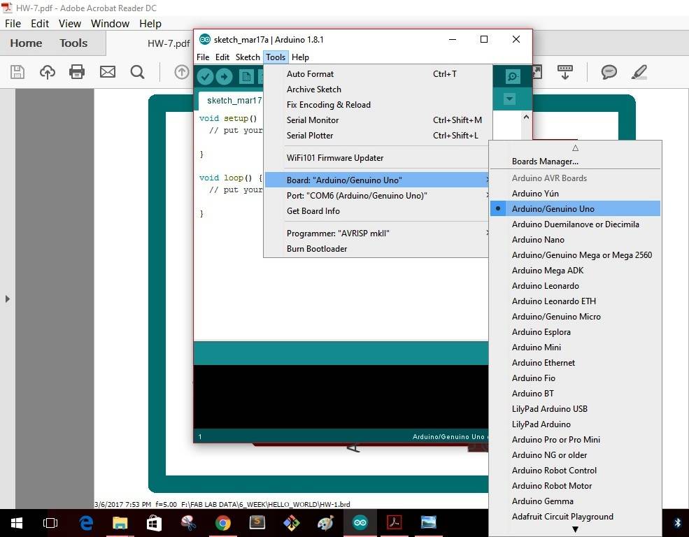
Step 2: In Tools ------- Port-------select "COM6(Arduino/Genuino Uno")--------
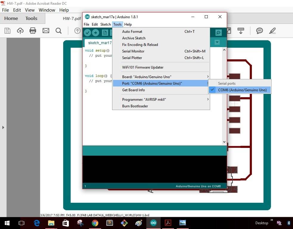
Step 3: In Tools -------Programmer-------select "Arduino as ISP"--------
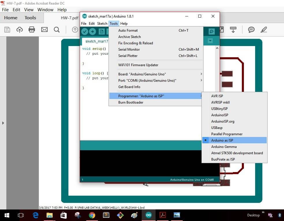
Step 4: In File -------Examples-------select "Arduino ISP"--------
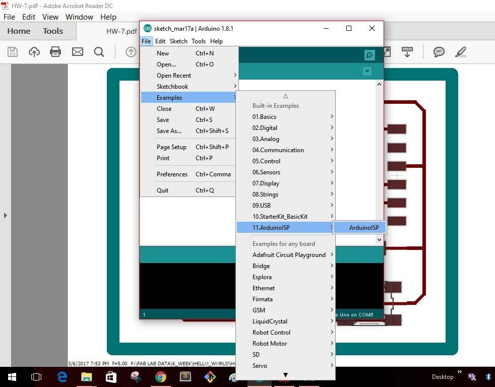
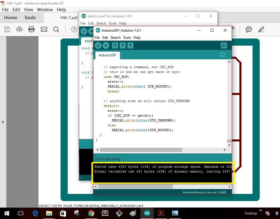
Step 5: As soon as I select the "Arduino ISP" the window as shown will pop up with a yellow icon as shown. Click the icon to upload the program into the Arduino board.
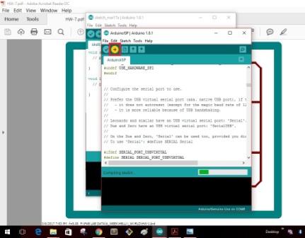
Once the uploading gets completed the window as shown below will give as message that uploading is completed.
This completes making the "Arduino" board as a programmer. I disconnect the board with my computer
The images show the communicator board after milling & before stuffing the board. And the next image shows the communicator board after stuffing
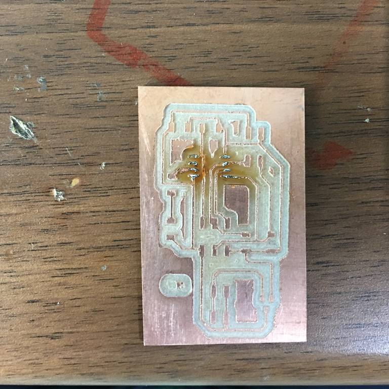
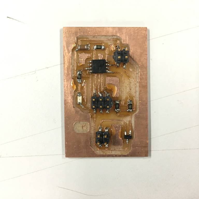
The images show the slave board after milling & before stuffing the board. And the next image shows the slave board after stuffing
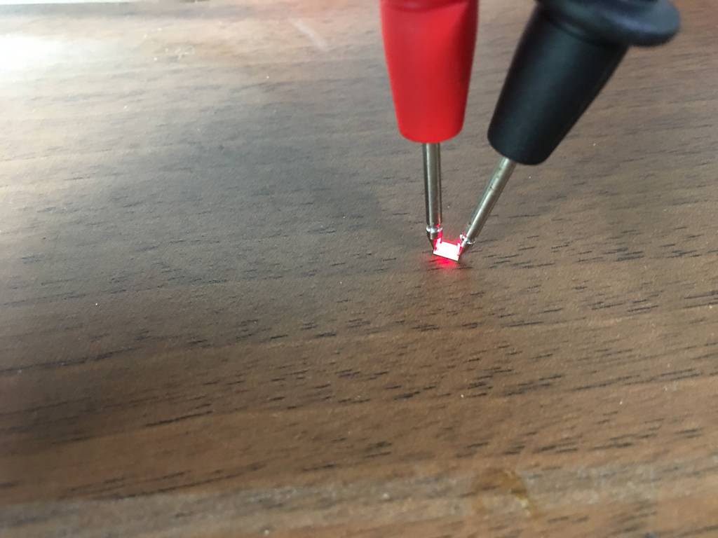
The image shows that the LED is in working condition before stuffing on to the board & before programming the board.
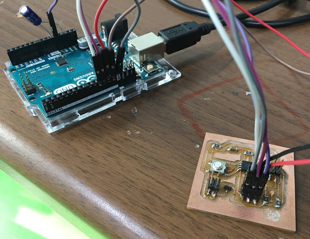
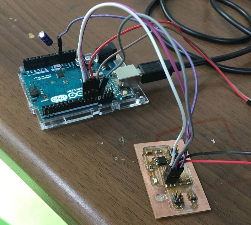
Step 6: Below images show the connections of the Communicator board & the Slave Board to the Arduino to upload the codes.
The image shows the LED glowing once the code is burnt to the micro-controller of the board.
problems faced & troubleshooting
When I burnt the program on the micro-controller of the master board the LED would glow as shown in the above image. Similarly when I burnt the program in the slave board Arduino gave me an error as shown in the image.

Then I started the troubleshooting of the problem occurred I searched the pages to find that the Library for "TinywireS" is not there in my Arduino version. Hence I downloaded the library "TinywireS.h" as randomly available on the Internet. Then I also installed the library for "TinywireM.h" inbuilt in the Arduino version.
After installing both the libraries again I connected both the respective boards to Arduino & burnt the program to the respective micro controllers.
Now the problem of error was gone, but still the boards were not getting communicated. At this stage I found that the library for "TinywireS.h" was of older version & required updated versions of library. Then I followed the link as mentioned here to study the answers for various queries related to Arduino Library. Arduino Playground
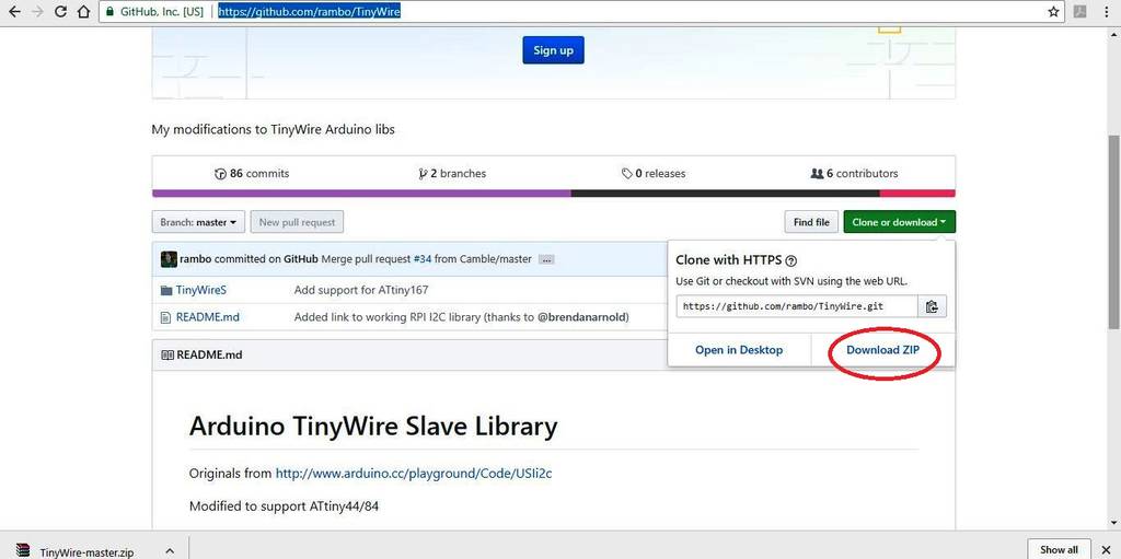
From this page I downloaded the required latest version of the library & the link for the same is given here. TinyWire Library The image here shows the page from where I downloaded the library.
After installing the library I again burnt the program into the micro-controller.
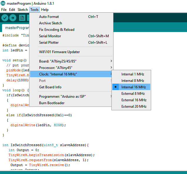
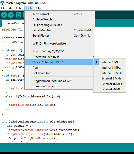
This time it was a different problem. The problem was that when the master program was burnt into my board I could observe that the LED glows after 16 seconds. Then I checked the same page for any solutions to find that the clock set in the Arduino was "Internal 16 MHz" was supposed to be changed to " Internal 1 MHz".
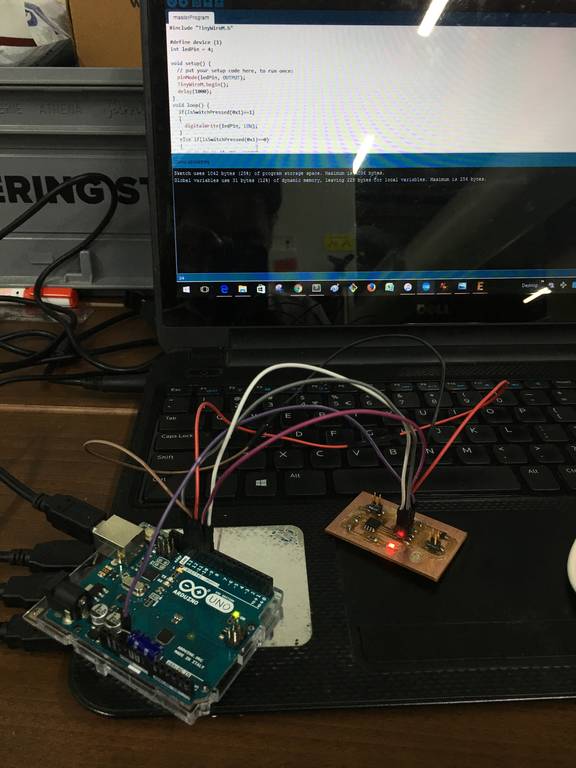
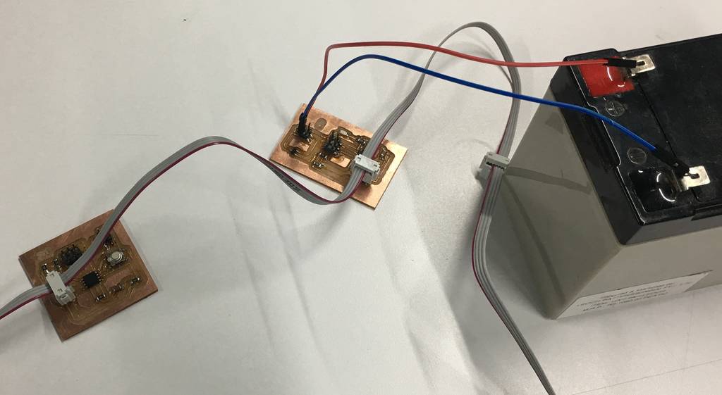
After doing these changes & re burning the program into the micro controller I was able to do communication between 2 boards. The connections for the boards are shown in the below images. After connecting both the boards with the pin headers, external 12V supply also need to be done as shown.
Working video
Networking & Communication from Clement Burga on Vimeo.
learnings of this week
- This week I learnt a new software Python for operating the stepper motors.
- This week I learnt to work with Gestalt nodes for operating the stepper motors.
- How to connect the Fab ISP with the Gestalt nodes for operating the stepper motors.
Files to download

This work is licensed under a Creative Commons Attribution-NonCommercial-ShareAlike 4.0 International License.