
Week 4
Electronics Production(Feb 17)
Assignment:
Make an in-circuit programmer See full tutorial here
- 17.2.2016 : Note from revision
- Note to self : things to do : try FreeCAD, 123dapp, grasshopper, Kangaroo
- document better in each phrase. work harder.
- use vinyl cutter
- Theo Jansen's  Strandbeest
- read Neil's How to make almost anything
- inflatable robot ?
- flexture and other type of joints...something more chalanging..
- try Antimony !
- 17.2.2016 : Note from lecture
- ways of making circuit board : Etching and machining. etching is not ..
- machining is good for prototyping. etching you can make several in one time.
- fixturing : to fix the board : biadesico is best.
- vinyl is good for.. + Kapton
- FR4 can not be machined
- make smooth and shiny solder joint
- a very cool website to see component simulation
- 18.2.2016 : basic electronic for ignorant (th)
	from prototype to production
- Conductor = ตัวนำไฟฟ้า เป็นวัตถุหรือประเภทของวัสดุที่ให้ประจุไฟฟ้าไหลผ่านได้หนึ่งหรือหลายทิศทาง
- Electric current = กระแสไฟฟ้า คือ การไหลของอิเลกตรอน กระแสไฟฟ้ามีหน่วยวัดเป็นแอมแปร์
กระแสไฟฟ้าก่อให้เกิดผลหลายอย่าง เช่นความร้อน และยังก่อให้เกิดสนามแม่เหล็กอีกด้วย
- Diode = ออกแบบและควบคุมทิศทางการไหลของประจุไฟฟ้า
- Resistance = ความต้านทานไฟฟ้า  คือ ความสัมพันธ์ระหว่างแรงดันและกระแสไฟฟ้าของวัตถุ
วัตถุที่มีความต้านทานต่ำจะยอมให้กระแสไฟฟ้าไหลผ่านได้ง่าย เรียกว่า ตัวนำไฟฟ้า
ในขณะที่ฉนวนไฟฟ้ามีความต้านทานสูงมากและกระแสไฟฟ้าไหลผ่านได้ยาก
ความต้านทานไฟฟ้า ใช้สัญลักษณ์ R มีหน่วยเป็นโอห์ม (Ω)
- Insulator = ฉนวนไฟฟ้า (isolatore) คือวัสดุที่มีคุณสมบัติในการกีดกั้นหรือขัดขวาง
การไหลของกระแสไฟฟ้าหรือวัสดุที่กระแสไฟฟ้าไม่สามารถไหลผ่านได้
- Capacitor/condensor = ตัวเก็บประจุ (condensatore) is a passive two-terminal electrical component
used to store electrical energy temporarily in an electric field.
- Active vs Passive Components : The strict physics definition treats passive components as
ones that cannot supply energy themselves,
whereas a battery would be seen as an active component since it truly acts
as a source of energy.
- 22.3.2016 : Eric Pan seeed.cc
 -
- 00_Introduction
At Opendot we have a laser cutting machine, a Trotec Speedy 100 flexx. The flexx line of laser cutters has both CO2 and fiber laser technologies: 60 watt CO2 laser, 30 watt fiber laser.
The full Laser a PCB tutorial is made by FabAcademy 2015 students at Opendot.
Nic explains us
how to prepare file for Trotec

getting the right focus is the tricky part

01_Preparing file : USB dilemma
Originally, We choose Andy's ISP design as reference because we like the idea of inserting directly standard usb to the pc..
Andy's board V 2.3 : works as standard USB male

Enrico has realised that there're 2 .. components instead of 1. So we should change the design to hello.ISP.res
hello.ISP.res : works as mini USB female

Things can go smoothly if we dont want to keep the cool feature which made us choose Andy's design in the first place, the direct usb connection
So the idea is to modify hello.ISP to have direct usb connection.. means
still pretty confused, I try to clear things out with drawing
Now we have a conclusion that we have to invert pin order which means we have to modify some traffic on the board
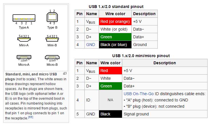
Back at home, Since I have no idea about what will be on the board and what I can and can not do, I try to clarify the connection by colors.
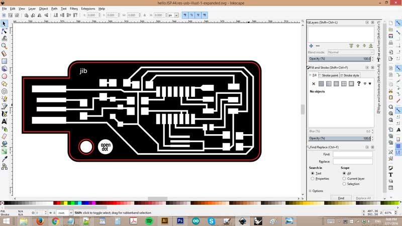
After downloaded both png image, I map out the components by colors : grey is Ground, blue is data +, yellow is data -, red is 5V
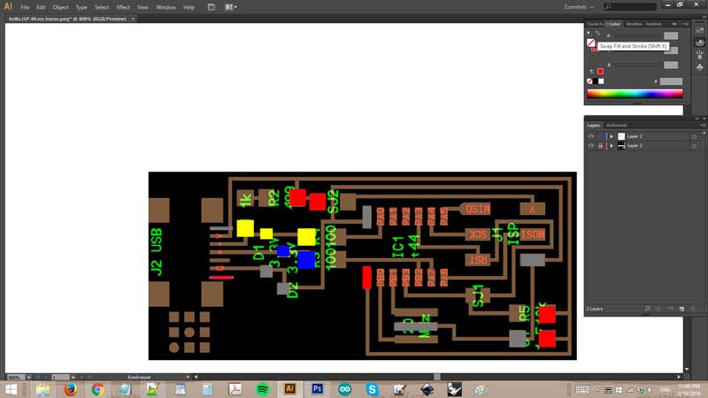
Then I try to be get all the traffic works.. then I encounter the problem at some points you can see here in the circle that too many roads in too little space so it create traffic jam
My thought was "if only there can be a bridge.. "
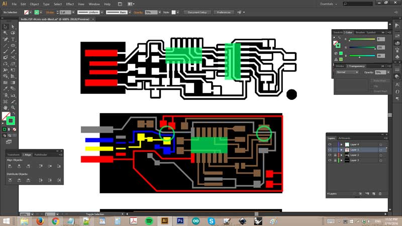
And actually there can be a bridge! in the next morning when I'm back at Opendot Nic also modified the board making bridge planing to use a 0v resistor so I made it too.
This is the V.1 file, open in Inkscape
02_Laser the board
The process is simple enough. Please check full tutorial
The most tricky part is getting the right focus.
But the most common mistake for Illustrator users is
Since the two programs use different default dpi, when import a file from illustrator to Inkscape, the resolution is changed and results in a smaller board..
I've realized that after seeing the size of the board while the laser cutter is running. So I interrupted the machine and pull the board out before it finishes. You can notice the size difference with the other board below.
After having modified the file, I printed it again. This time scale looks right but the board is not cut.
Actually it does cut one part (the inner circle) but left out the border.


I went back to check the file and it was my fault.. then I discovered that the border line is not pure red (R255)
A day after, with a modified file I have another go with the laser cutter. A new problem occurs, the board is not properly engraved so the cut can not get through !

What could be the problem ? Since the file looks perfectly fine, it must be hardware problem. My first ipothesis is that the surface is not clean probably the adhesive I put under the board to keep it fixed on plexi created the problem.
Or may be the plexi is a bit dirty after everyone has put and took out the adhesives so many times.. So I cleaned everything and have another go
Yet the problem remains.
Having a consulting with Pigi, we fixed the focus to be centered on the unengraved part and then make the machine have another go.
This time looks better.. so after some minutes here's a lovely results

Just wondering, could be it be that someone moved after studio cleaning yesterday and the machine is not properly calibrated ??

Even still not sure what was the problem, I continue with another design of the board. The engraving has the same problem but I forgot to take photos of it. So I did the same trick : re-calibrate focus and restart the process on the sme board.
Eventually, now I have 2 good-looking boards : )

03_Soldering
Get ready to solder, with a printed diagram and reference board soldered from Nicola(on the right). The soldering iron was set at 280 temperature so leave it that way.
(after some hours I discover that 290 is a lot better)


My hand was shaking badly ! this is the result of the first component.. I'd say not bad

Keep going on.. the 3 pin component is really difficult. I made bad solder and it made a short circuit.
Then comes the IC1t44 which is a nightmare.. look how my solder was ugly!

I think I went on for 2 hours or so.. finally got to the last part, the 6 pins.

And.. there you go!

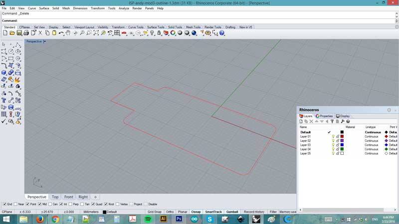
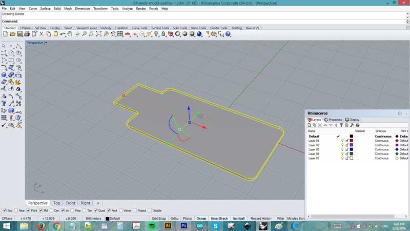
Now I'd need a base for the usb connection part.. so I use the outline file from board design and extrude it in Rhino.
Then export in .stl and open with Cura
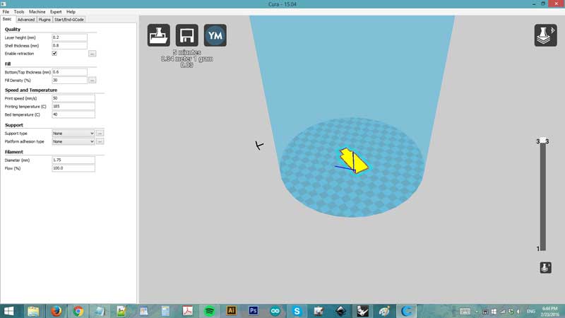
And print it with Wasp

Here it is..


04_Programming
almost FAIL ! :)In short, I can not get it work.. first thing first I can not get it work on my pc which is Windows so I program on Ernesto's and Nic's mac.
On mac, I have error report after "make fuse" phase.. (forgot to take photos & screenshot)
First thought was that the soldering is not good enough so I made it better in many points. but still not working. So I checked all the connection by the tester, comparing with the diagram and I found a HUGE & STUPID mistake I made : I skipped the vcc pin of the IC1t44 !!
So I made a jump with cable and this is how it looks now

The cable jumper works but I still can not get the board programmed. still got the same error at the "make fuse" phase.. My guess is : 1. bad connection due to bad soldering 2. wrong traffic design 3. wrong components
One thing to note is that everyone here at Opendot still can not get it work so this also could be a mistake that everyone have in common, which means components.
In any case, I should try solder another board, the original design one.
Update : I left Opendot last night at 11PM with full sense of failure :D Meanwhile Ernesto and Nicola was still there
This morning we've got a message of victory
Good morning everyone! Last night me and Nic got it worked :) You have to use a different capacitor, a bigger brown one, you can see it from fab isp of Enrico
So I started as soon as I arriverd at Opendot. I took Nic's board to check the differences

Took me a bit to find he right capacitor. Actually the one we put on board was already the right one, according to the label on the bag.
Instead, this brown one is without label so I can't even know what it is...

Anyhow, I desolder the old capacitor and put a new one
then program it using Enrico's ISP... and .. BINGO !

Fits nicely with usb port

Recognized ! 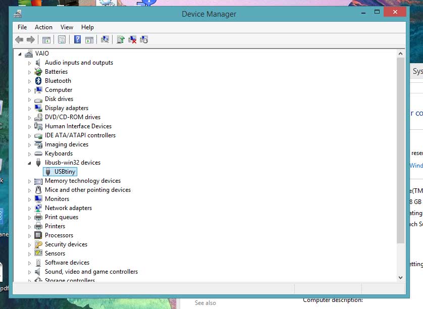
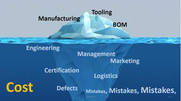
05_Conclusion
Mistakes made - file scaling from Illustrator to Inkscape - wrong board design, due to late work - focusing the laser cutter Trotec - wrong component assembly, due to bad organization in storage ??
Things learned - working with Inkscape - lasering a board using Trotec - soldering, desoldering
Things not fixed - windows AVR problem , probably resolved in this thread found by Francesco
I am really happy with the result. Now I know how to solder and how to laser a board : )
Download files : board(svg), 3d base(stl) << previous | next >>