
Week 6
Electronics Design (Mar 2)
Assignment:
redraw the echo hello-world board, add (at least) a button and LED (with current-limiting resistor) check the design rules, and make it extra credit: simulate its operation


01_Design a PCB with Eagle
Andrea gave us a lecture on Basics Electronic and on how to use Eagle
Starting from the example
Neil gave us, I started make a schematic drawing. We have a different resonator so thanks to the library made by
Ernesto we can put the correct package.

Then in order to add a push button and a LED, I take references mainly from Mattia who is last year student at Opendot
Mattia has also link this LED calculator. I still have no idea how to calculate the resistor..
this is how my schematic turns out

Then I started with Board layout. I have problem with routing snap so I tried to use Autoroute but it looks too closed to each other

Then I discovered that there's a grid snap and the default grid size is too big for this case. I changed grid size to 0.025
and change the display to On so that I have a clue where things go

Also changing the width of route to 0.01 helps

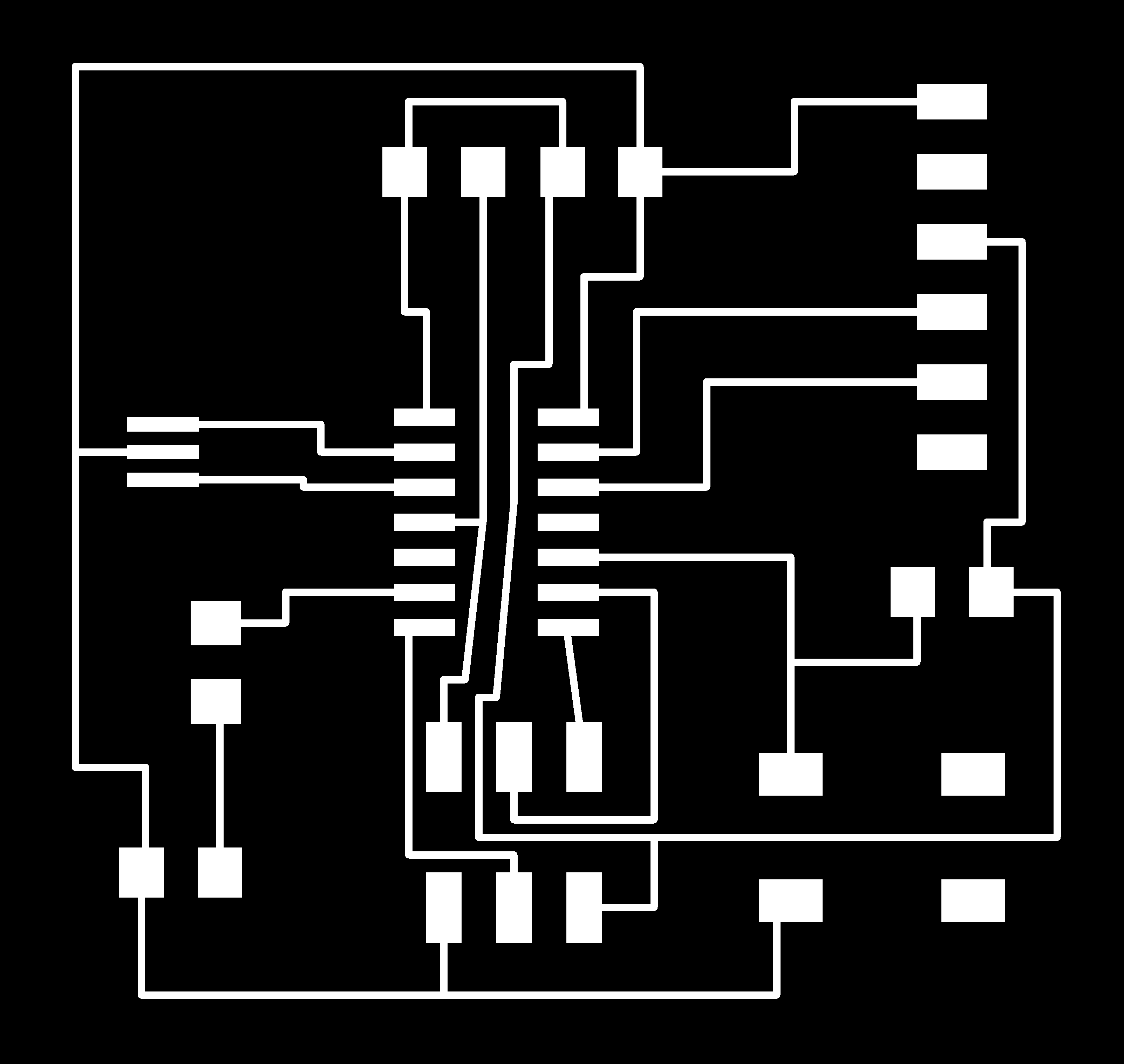
Finally this is the board. Make sure to check DRC to see if there are any errors

02_Export an image
Now it's time to export. In order to be used wth the laser cutter, I'll need white route on black background
so make sure it is changed in Options>User Interface

hide every layers except the first one

then Export>Image in Export Image window, tick Monochrome. I exported as a png with 2000 dpi resolution.
Then I made some modifications in Inkscape : adding text and red cutting line

Printed board

Soldered !


with the help from Ernesto (again) we verified that the board works !

Download files : Schematic and Board(zip) for Eagle Board file(svg) Export board image(png) << previous | next >>