This week we are going to make an output devices and program it to do something.
I made two output devices. One is a single LED with fading effect. The other is a LED array with charlieplexing.
|| LED
Here is the layout of circuit board. I attached a LED to a PWM pin of attiny45 and you can find the design file on the right.
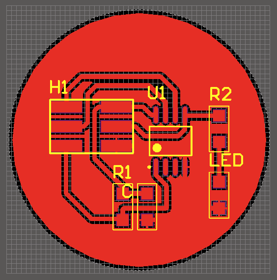
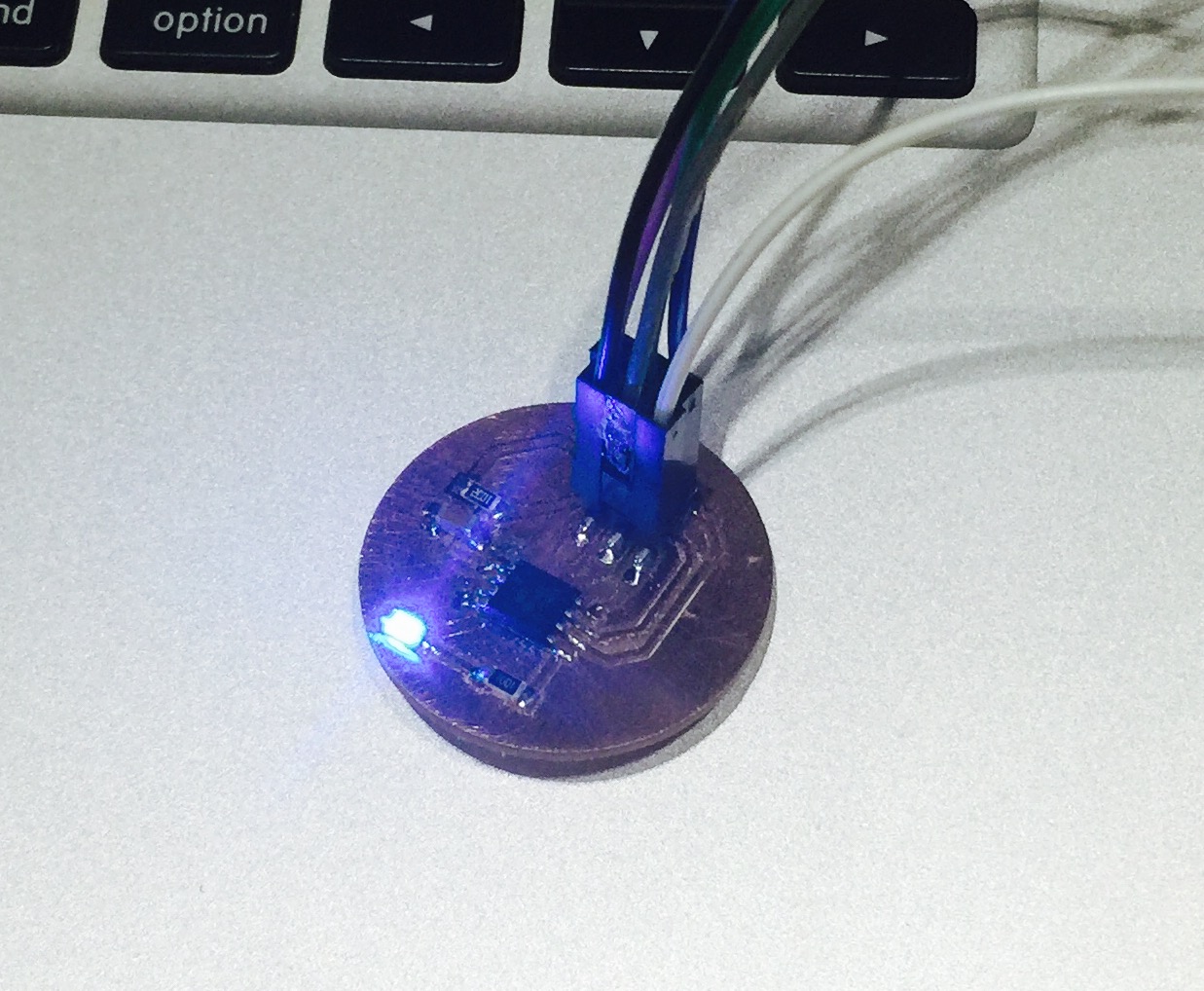
After the board got milled and soldered, I used Arduino to program it. The outcome is a fading LED. You can find the Arduino sketch on the right also.
|| LED Array
Besides a single LED, I made an LED array this week also. Charlieplexing is quite interesting.
This 4 x 5 LED array is controlled by 5 pins using a tech named Charlieplexing. This is a technology that enables n pins to control n*(n-1) pins using code of all pins not just status of two pins.
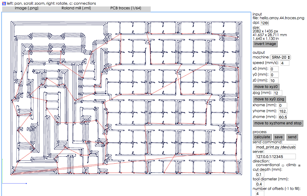
First I used Fab modules to generate .rml file from the PCB design file. You can find the PCB board files on the right.
After that, I started to program it.
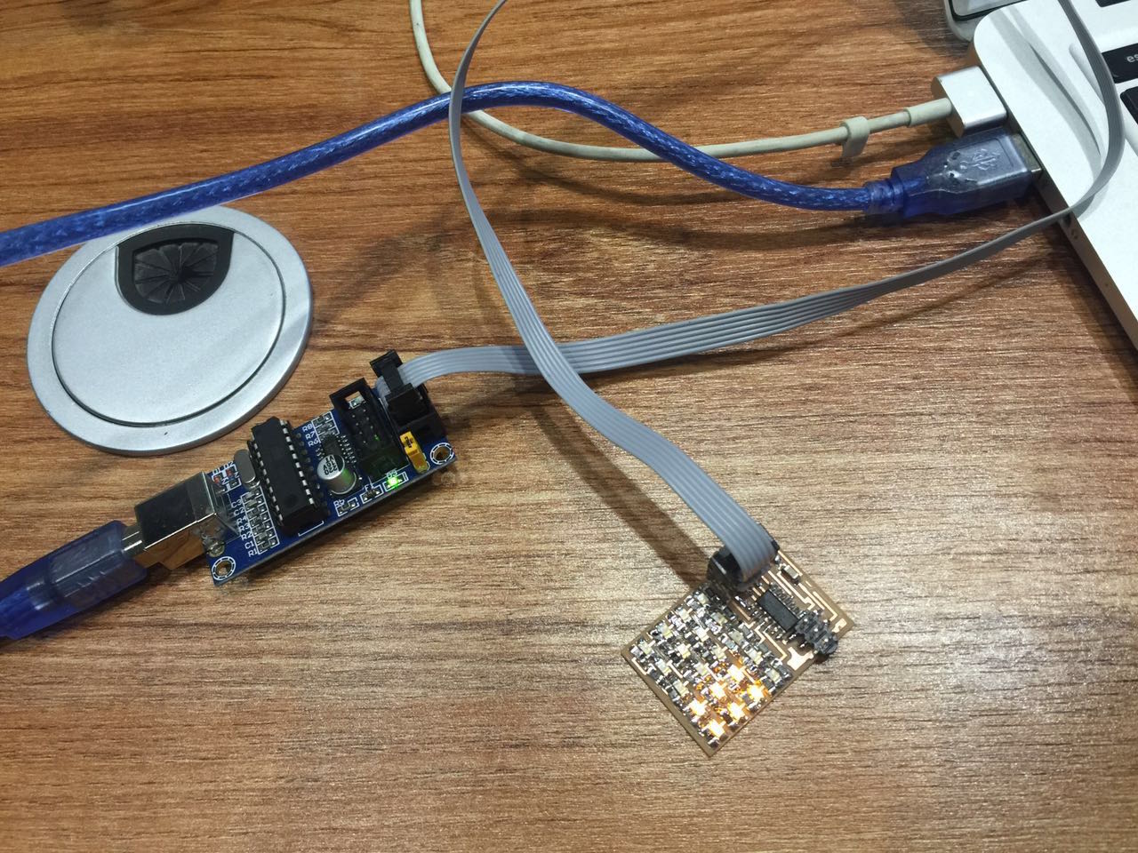
I used USBtinyISP as a tool to do the programming. The connection is as following:
The schematic of 5 pins to control 20 LEDs using Charlieplexing is as below:
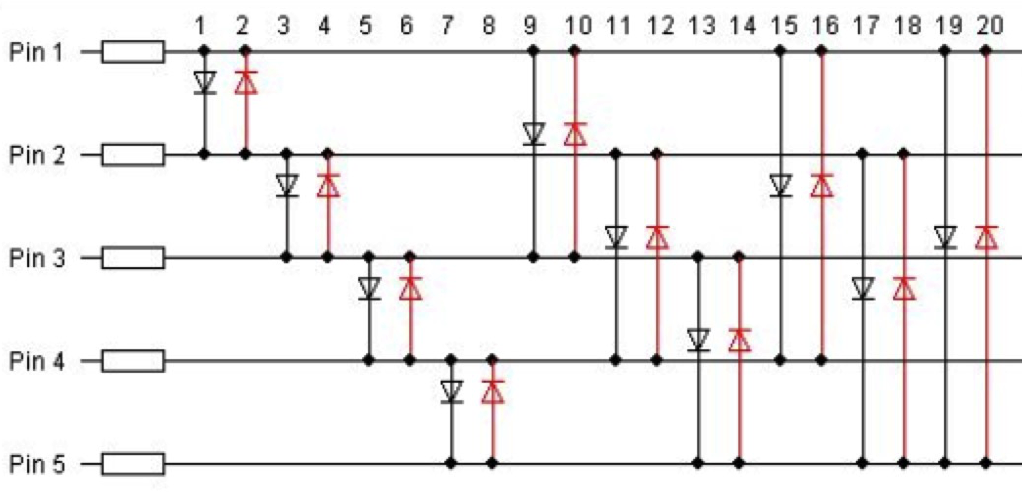
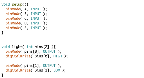
So when control an individual LED via Arduino IDE, using two pins that directly connected to the target LED is not enough. We need to take the pinMode into consideration also.
And then I made a scanning light effect as below: