This week our assignment is make an input device. I made a button for this week.
You can find the design file on the right.
Some notes here about the unhappy moments between Altium, a PCB design software, and the milling machine in out lab, SRM-20. From the design file .PrjPCB in Altium to .rml file that SRM-20 needs, there is a not straightforward journey involving several tools:
design scheme and PCB in Altium:
-> output .pdf file
-> generate 300dpi .png file for fab modules online tool
-> generate .rml file for SRM-20
For the traces on the board, we use 1/64 tool to mill it. 1/64 inch is around 0.4mm, but when I set the width of routing as 0.4mm, a lot of traces break. A lot of reasons can result this. Tolerance of the machine, data missing during format changing, etc. However, after several tests, here are the settings in Altium fit for this case:
- clearance: 0.6 mm
- routing: 0.6mm
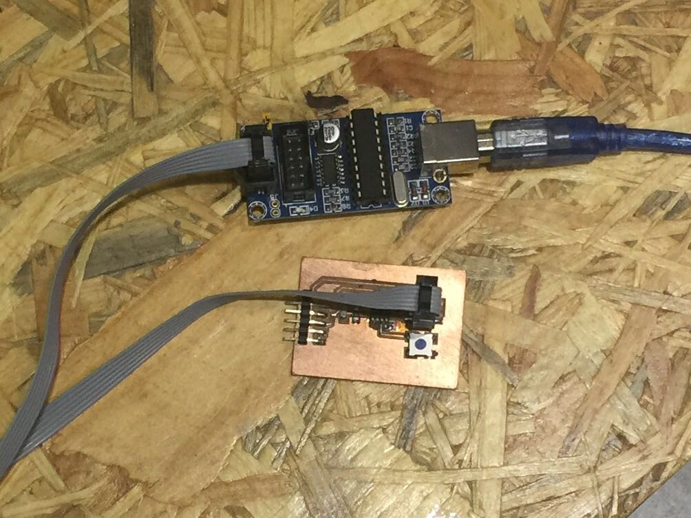
After milled, the board is connected to computer with USBtiny ISP:
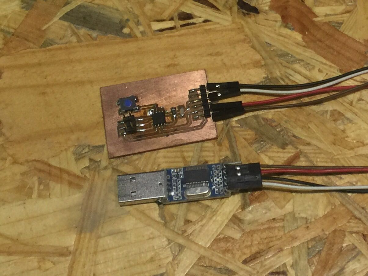
The programming is quite easy. I read the status of the button and output it to serial monitor. You can find my sketch on the right also. After uploading the code, I used a USB-TTL module to send the signal from the botton to computer.
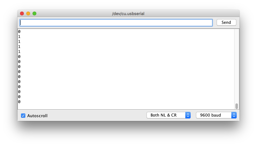
Now check the information from the serial monitor in Arduino IDE:
Here is the video: