Study archive - Week 4
Electronics production
The lecture 4 on Wednesday 17.2 was about electronics production - how to create, solder, and program circuit boards. PCB (print circuit board) production was the first topic and also a part of this week assignment.
The task of this week was to make an in-circuit programmer using ready-made circuit design. In our fablab Oulu, we choose Valentin circuit design. Antti, Juha, and Jani were helpful and knowledgeable. We had a nice team work. See also their documentation (Juha, Antti.)
PCB production
The following resources were used:
- Circuit board design files provided by Valentin (ISP.png and cutout.png)
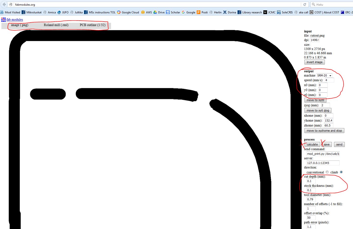
- Fabmodules.org program for setting milling parameters
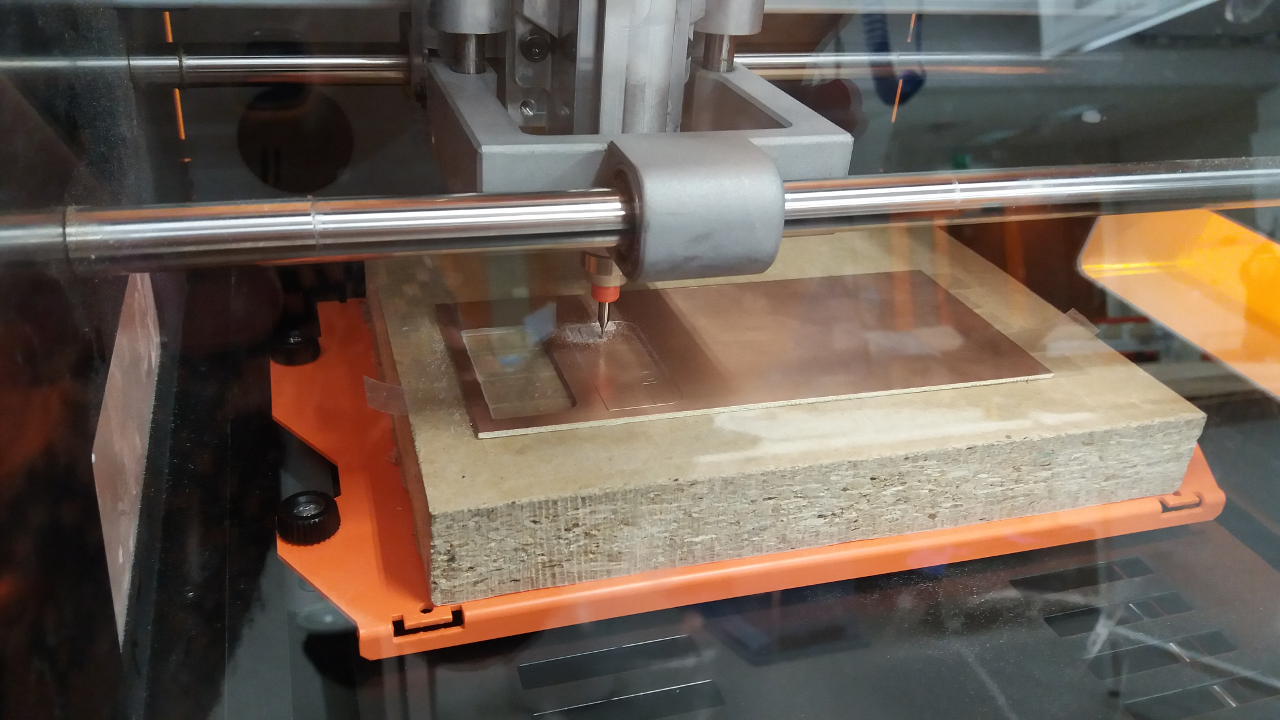
- Milling machine Roland SRM-20
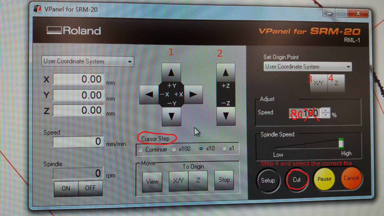
- Software VPanel for SRM-20
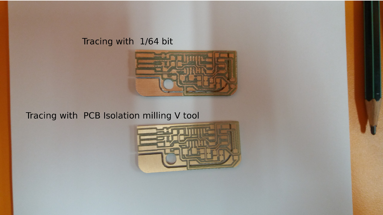
- For materials we used FR4 board and bits with the specifications: 1/64, 1/32 and PCB Isolation milling V tool with diameter 0.2-0.5 mm. The 1/64 bit was discarded due to poor tracing quality; instead we used for the final board the V-shaped tool.
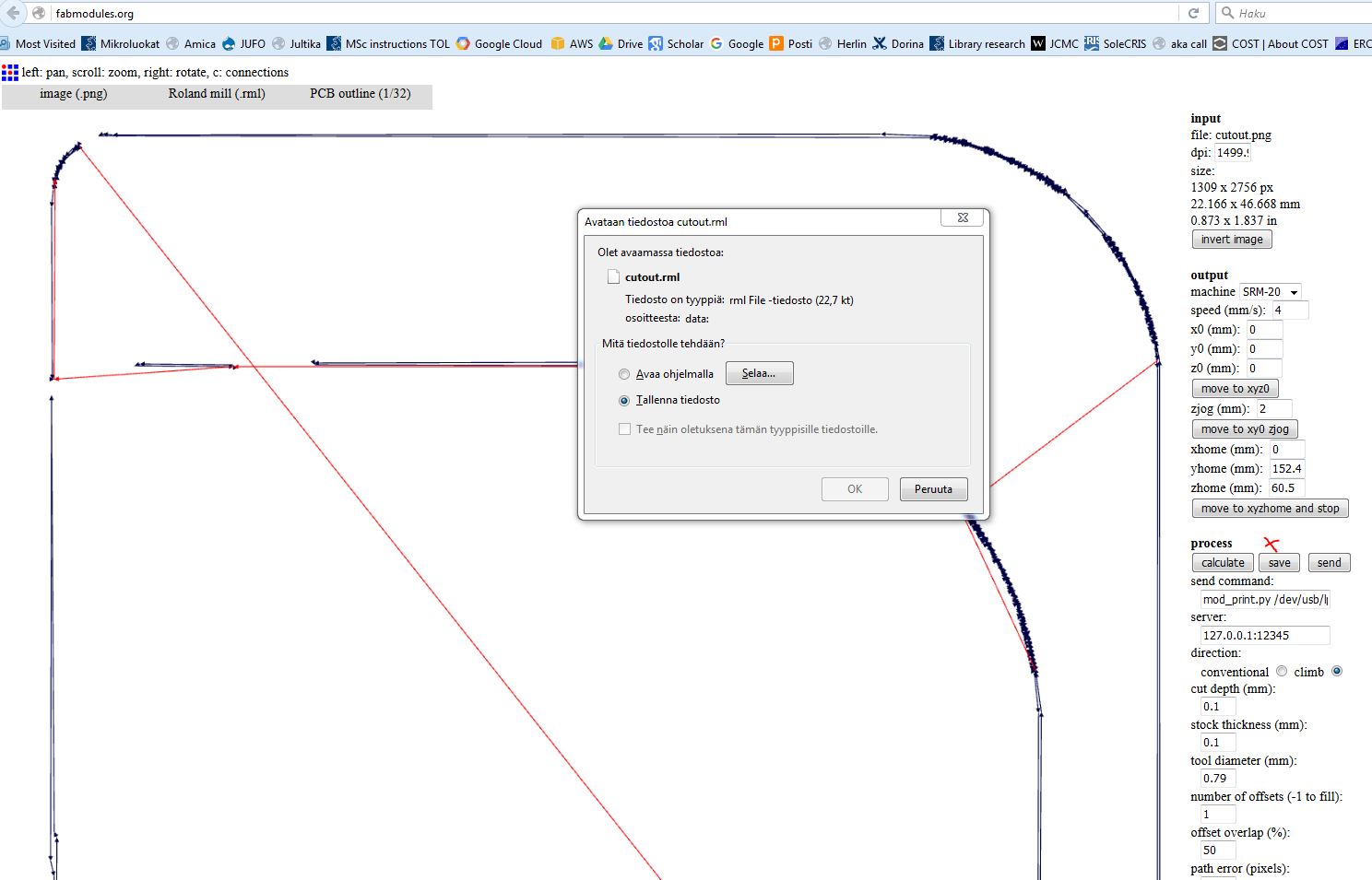
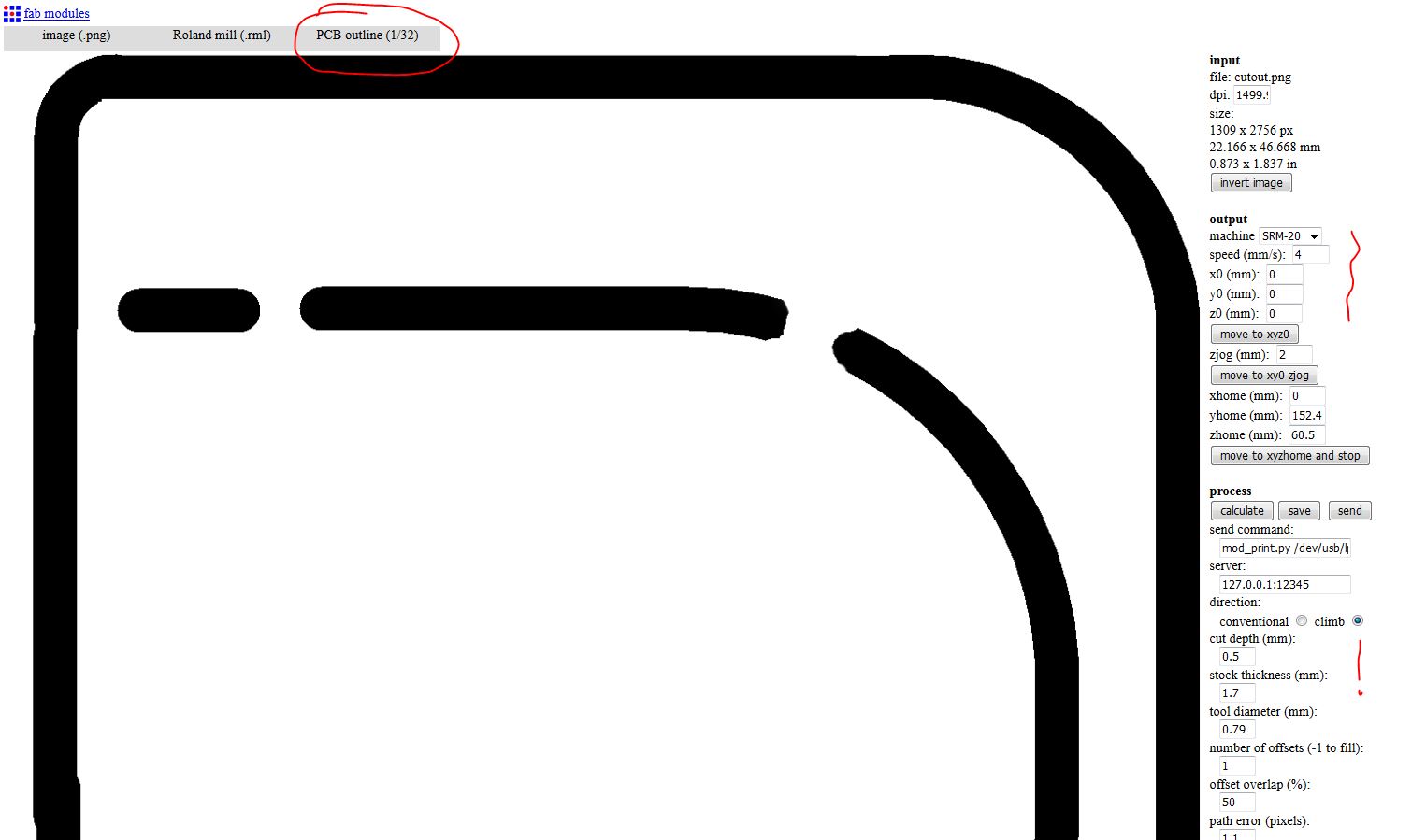
The main steps are to create the .rml files using Fabmodules.org and then to use VPanel for SRM-20 to mill the board. Three .rml files are created:
- cutout_step1.rml to test the tracing parameters. A bit for tracing is used. This step does not produce a cut, but an outline on the board and the purpose is to see if the cut depth parameter for tracing (e.g., 0.1 mm) is good enough or has to be increased. If the result is not satisfactory, the step can be repeated with a different value of the cut depth. The input file is cutout.png.
- ISP_step2.rml to create the traces. The same sharp bit is used as in step1.The input file is ISP.png.
- cutout_step3.rml to cut the board. A 1/32 bit was used.The input file is cutout.png.
At each step above, different milling parameters are used. See pictures below and also the PCB obtained.

In the VPanel program we set the origin point for the milling. We have to select User Coordinate System and to move the cursor to the place on the board we define as origin. Moving the cursor is done with the arrows on the VPanel. The Cursor Step indicates how fast the cursor in the milling machine is moving towards the desired place (continue: very fast; x1: very slow). To set the origin point we press XY and Z buttons (3,4 marks) When we change the bit, we only adjust the z coordinate; the X and Y remain the same (so we press XY button withou a priori adjusting the position with the arrows).
Assembling and Soldering
The following resources were used:
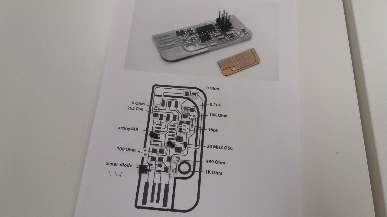
- Circuit board plan file provided by Valentin (plan.png)
- Fablab Oulu electronics workbench for manual soldering
- Components specified in the plan.png file.
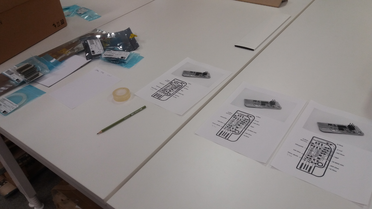
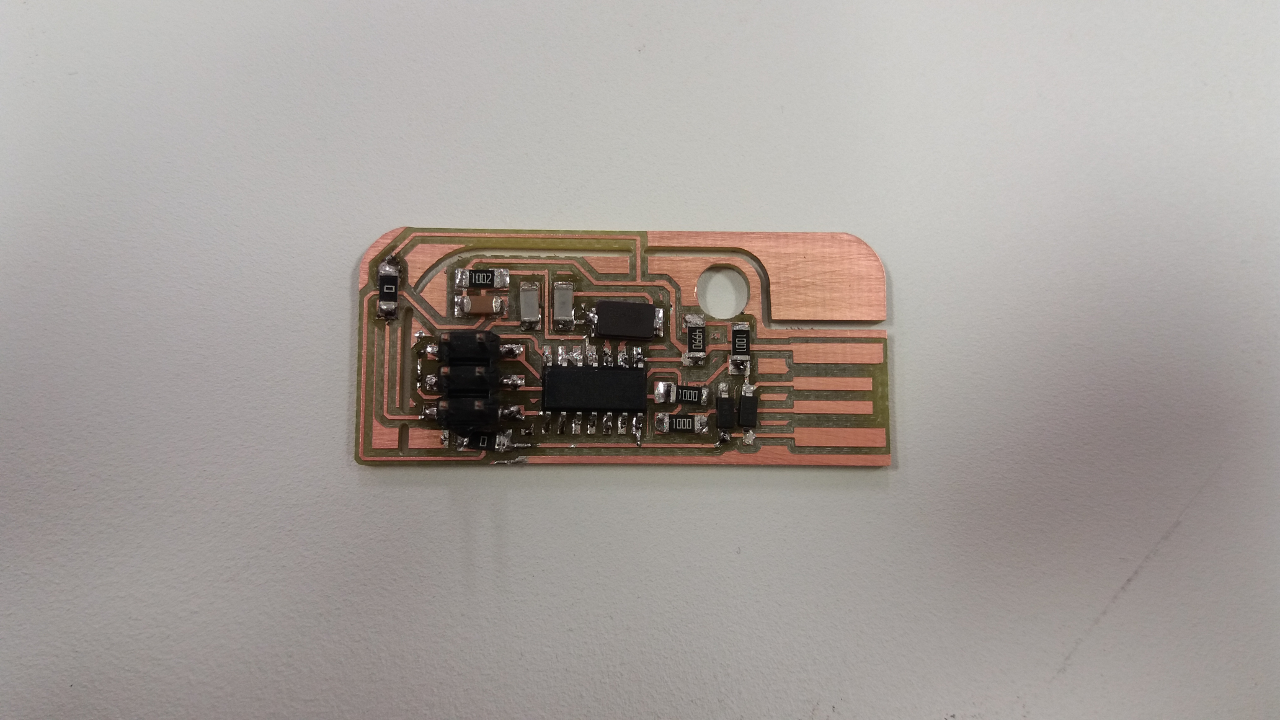
The pictures below show some steps in the assembling and soldering process and the result. For the assembly, the right componets were selected and mapped onto the PCB model.
Programming
The following resources were used:
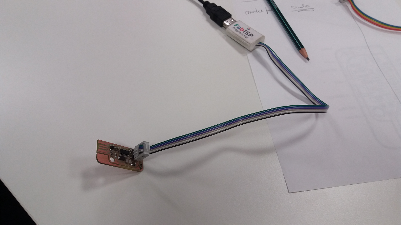
- FAB ISP programmer provided by Jani
- Fabacademy.org tutorial for FabISP Programming.
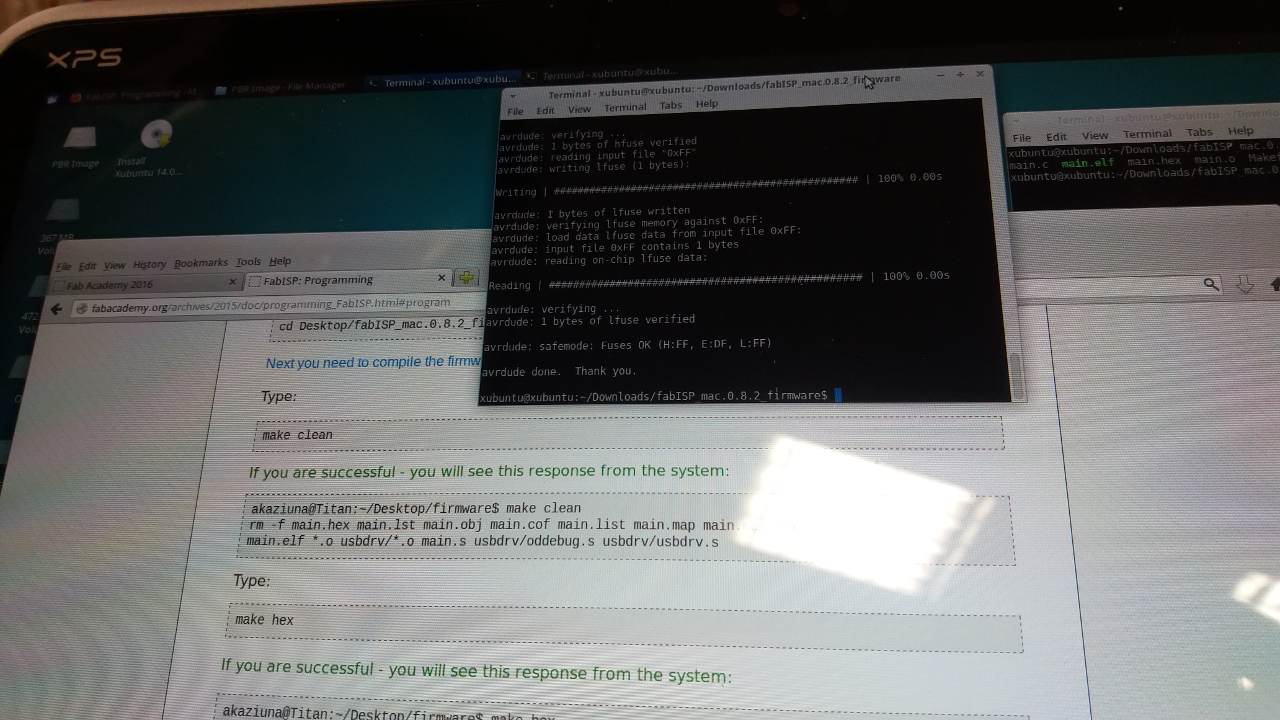
- Installation of Linux USB and AVR programming SW provided by Juha for programming the usb board. The following commands were used for programming after the installation was complete: 1) make clean; 2) sudo make hex; 3) sudo make fuse; 4) sudo make program.
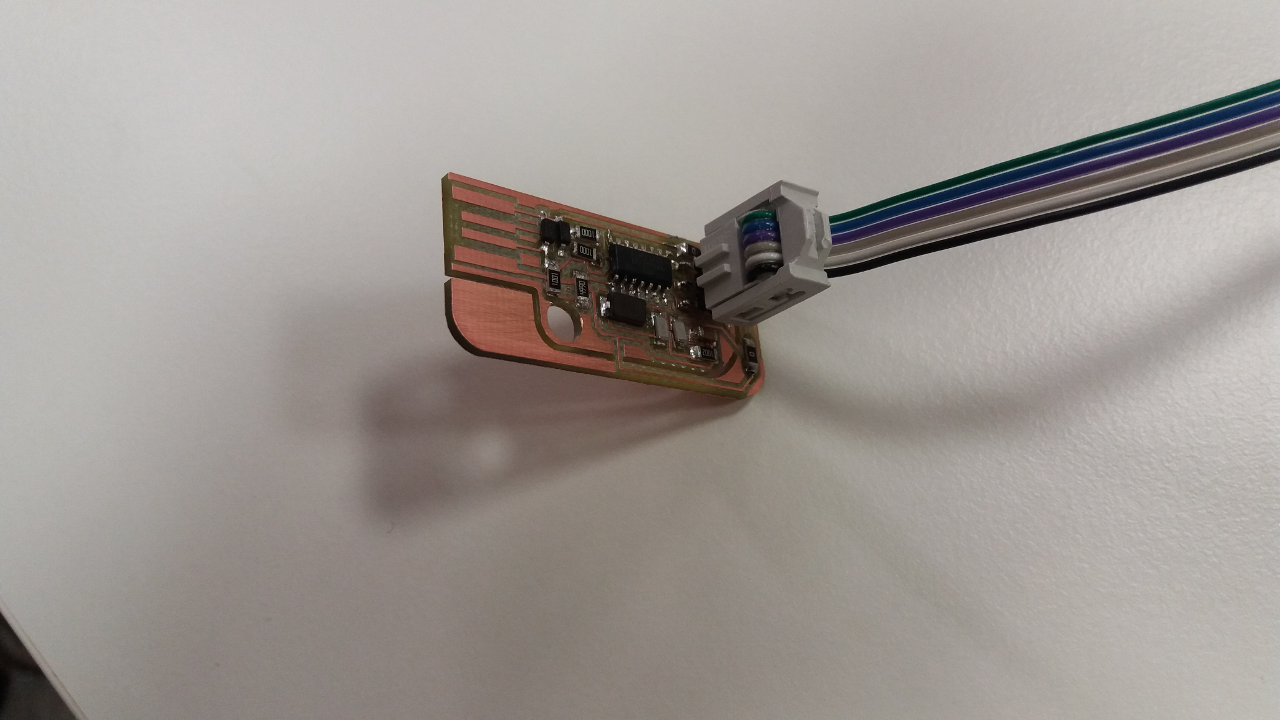
The pictures below show some steps in the programming process.
The summary of electronics production:
- Team work was very important and successful.
- The order of soldering the components is important. I have done both soldering and desoldering to correct mistakes. Juha has written recommendations on the ordering on his webpage.
- I found David's documentation on all steps including soldering order also very good.
Update 2.3.2016
The online homework review on Tuesday 1.3 with Bas revealed that I had a mistake on the board; the capacitors were not oriented right. Thus I had to correct the board by desoldering the capacitors and soldering them again with the right orientation. See picture below.
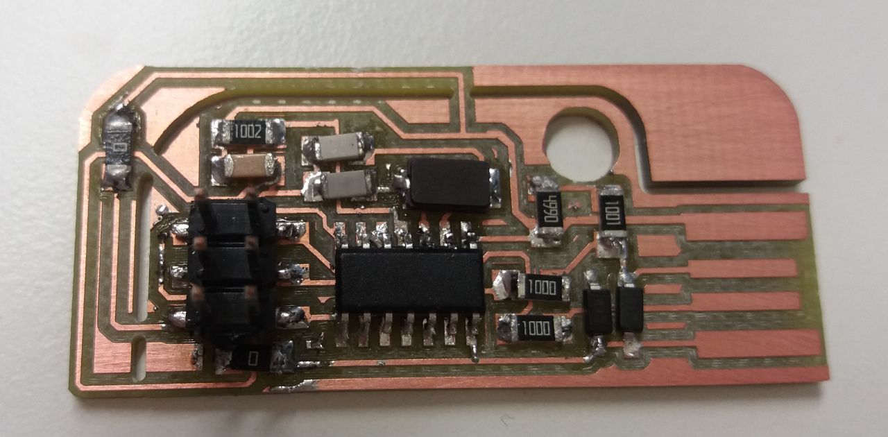
Luckily the mistake was on capacitors and did not affect the programming which was successful from the first try and thus was not needed to reprogam the circuit board. Many thanks to Antti who has helped me with the desoldering using a special tool for the task.
Hero shot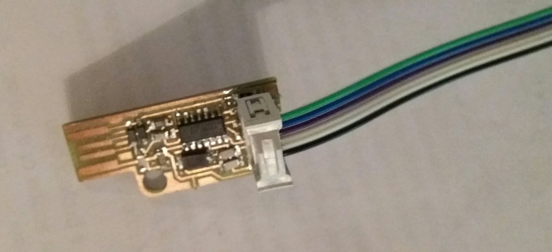
Summary of Tools used
Software
Fabmodules - to set the milling parameters for the .rml files
VPanel - to set the milling parameters for the milling machine
Linux USB installation and AVR programming SW - to program the usb board
Hardware
Milling machine Roland SRM-20 - for making PCB
Soldering workbench and tools
FAB ISP board


