Study archive - Week 19
Project development
This page summarizes the project development process starting with initial idea, continuing to the final project idea, and then presenting the final result. More detailed description of the project execution is on Final Project page.
1. Initial idea
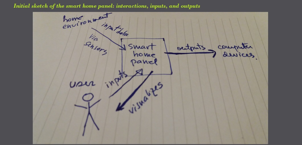
The initial proposal for Fab Academy project was to design and build a prototypical smart home device that is interactive and transmits data from user and environment to a computer device via wireless sensors.The image below shows the basic interactions, inputs and outputs.
2. Final idea
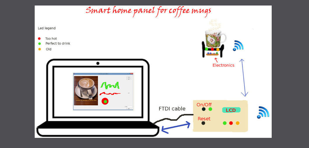
Later, after a few iterations of defining the project, I have decided to make a system that measures the temperature in a coffee mug and the time, and then the temperature and time can be visualized on the LCD. The information is also wirelessly sent to and then displayed on a computer device and control panel. With the control panel the user is able to control the device and the data.
A sketch of the system and interactions is shown below.
 Basic features (old version)
- activate/deactivate system (reset)
- measure temperature in coffee mug
- send data (temperature, time, and reset signal) to computer device and control panel
- display temperature, time, reset on LCD
- display temperature, time, reset on GUI on a computer device screen
- mug holder (3d printing)
- temperature sensor for coffee mug
- control panel (plywood laser cutter and milling)
- on/off buttons for activate/deactivate/reset
- LCD
- (LEDs, optional)
- networking components (wired and wireless)
- power sources
- computer and GUI
| Material/component | Source | Cost |
|---|---|---|
| ABS-M30 for the 3D printing | Fablab Oulu | n.a. |
| Support material for the 3D printing | Fablab Oulu | n.a. |
| NTC thermistor | Fablab Oulu | 2.98 USD |
| Microcontroller ATTiny 44A | Fablab Oulu | 1.51 USD |
| LEDs x 6 (max 10) | Fablab Oulu/SparkFun | 3.5 USD |
| Other electronic components | Fablab Oulu | about 10 USD |
| FTDI cable | Fablab Oulu | 16 £ |
| XBee x 2 | Fablab Oulu/SparkFun | 50 USD |
| LCD | Fablab Oulu | 8.38 USD |
| On/off switch | Fablab Oulu | 1.95 USD |
| Plywood | Fablab Oulu | about 10 USD |
| Total | -rounded- | about 100 USD |
| Part made in Fablab | process used |
|---|---|
| 1. Mug holder with slot for electronics | 3D design and 3D printing |
| 2. Electronic board for LCD and control panel | Electronics design, production, and embedded programming |
| 3. Electronic board for temperature sensor | Electronics design, production, and embedded programming |
| 4. Wired and wireless networking | Electronics design, production, and embedded programming |
| 5. Plywood case for control panel | 2D design and laser cutting |
| 6. GUI | Interface and application programming |
- Week 20 (16. - 22.5) Define final project concept DONE
- Week 21 (23. - 29.5) Make bill of materials and adjust final project concept based on availability of components DONE
- Week 22 (30.5 - 5.6)
- Week 23 (6. - 12.6) Work on electronics production including networking and HCI programming
- Week 24 (13. - 17.6) Finalize the final project, documentation, and presentation. Aim is to present on 17.6.
- Week 25 (20. - 29.6) Revise weekly assignments (CNC, output devices, networking)
(1) Design and fabricate the physical interface: the control panel case and the mug holder
(2) Start the electronics design and production
The use of leds on mug holder as well as on the control panel has to be designed if time allows in Week 22. In week 23, the calibration of the temperature sensor has to be done.
The project is evaluated a success if the mug holder sends correct data to the panel and computer, displays it and the user is able to interact with the control panel and GUI. Random users can also be asked to provide feedback.
The product is a proof-of-concept and the aim is to extend it further by adding more functionality and/or design features. The project aims also to rise students/children interest in electronics, programming, and especially data analytics. By using a simple, everyday situation to generate data, people of all ages and backgrounds can be involved in the process of creating visual analytics.
3. Final result
What is the deadline?The deadline for finishing and presenting the project is 17 June 2016. The deadline for finishing weekly assignents documentation and final project documentation is 30.6.2016.
Given the strict deadlines, I had to scale down the final project in order to deliver a finished and functional prototype by the project deadline (17 June). Thus, I had to remove the wireless networking from the implementation because one of the Xbee shields got broken and I did not have a second one available for use. Moreover, I had also to leave out the GUI implementation due to the lack of time for this task to complete. I focused on implementing LEDs and LCD for displaying the temperature. I have implemented also a button for controlling the LEDs.
Time management and task completedThe planned schedule was managed so that the following tasks were completed in time.
- Week 20 (16. - 22.5) Define final project concept DONE; and REFINED (scalled down) during Week 23
- Week 21 (23. - 29.5) Make bill of materials and adjust final project concept based on availability of components DONE; and REFINED later (see below the final BOM)
- Week 22 (30.5 - 5.6) (1) Design and fabricate the physical interface: the control panel case and the mug holder
- Week 23 (6. - 12.6) Work on electronics production including networking and HCI programming DONE, but SKIPPED networking and GUI; focused on LCD programming
- Week 24 (13. - 17.6) Finalize the final project, documentation, and presentation. Aim is to present on 17.6. DONE the following: finalizing the physical interface, temperature NTC programming in C, the presentations slide and video; live presentation on 17.6. Documentation postponed for after project presentation.
- Week 25 (20. - 29.6) Revise weekly assignments (CNC, output devices, networking) DONE; also Final project documentation was included here
DONE; and REFINED in Week 24
(2) Start the electronics design and production
DONE
Thus the basic functionality, BOM and processes were refined as follows:
Basic features (updated)- activate/deactivate system (using the FTDI power cable connected to the computer)
- measure temperature in coffee mug
- send data (temperature) to control panel
- display temperature on LCD and LEDs
- control the LEDs with button on the control panel
- physical user interface (control panel): button, leds, LCD, mug holder integrated in a functional prototype
- mug holder (3d printing)
- temperature sensor for coffee mug
- control panel (plywood laser cutter and milling and acrylic components)
- LCD
- LEDs
- on/off buttons for activate/deactivate LEDs
- power source (5V via FTDI cable connected to computer)
- computer
| Material/component | Source | Total Cost |
|---|---|---|
| ABS-M30 for the 3D printing | Fablab Oulu | n.a. |
| Support material for the 3D printing | Fablab Oulu | n.a. |
| NTC thermistor | Fablab Oulu | 2.98 USD |
| Microcontroller ATTiny 44A (x 2) | Fablab Oulu | 3 USD |
| LEDs (x 3) | Fablab Oulu/SparkFun | 2 USD |
| FTDI cable | Fablab Oulu | 16 £ (21.5 USD) |
| LCD | Fablab Oulu | 8.38 USD |
| Button | Fablab Oulu | 1.95 USD |
| Other electronic components (resistors, capacitors, crystal resonators, pin headers, etc.) | Fablab Oulu | about 10 USD |
| Wires | Fablab Oulu | about 2 USD |
| Nuts and bolts | Fablab Oulu | about 1 USD |
| Plywood | Fablab Oulu | about 10 USD |
| PCB | Fablab Oulu | about 3 USD |
| Acrylic | Fablab Oulu | n.a. |
| Total | -rounded- | about 65 USD |
| Part made in Fablab | Process used |
|---|---|
| 1. Mug holder with slot for electronics | 3D design and 3D printing |
| 2. Electronic board for LCD and control panel | Electronics design, production, and embedded programming |
| 3. Electronic board for temperature sensor | Electronics design, production |
| 4. Electronic board for temperature sensor and control panel programming | Electronics design, production, and embedded programming |
| 5. Plywood case for control panel | 2D design and laser cutting |
| 6. Acrylic protective screens (x 2) for LCD and electronics | 2D design and laser cutting |
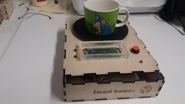
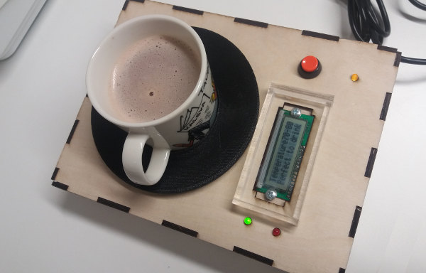
Time management was successful. The final project was successful. The system measures the temperature in a mug placed on the mug holder. The temperature is displayed on the LCD screen by providing an estimate (too hot - higher than 80 degrees C; too cold - lower than 70 C; and perfect to drink - temperature between 70-80C). This information is also shown on LEDs: green led is on when temperature is perfect; red led is on when temperature is too low or too high. Another LED is also on when the system is powered up (connected to computer via FTDI cable). The system has also a pleasant and intuitive physical user-interface.
The system ready to use.
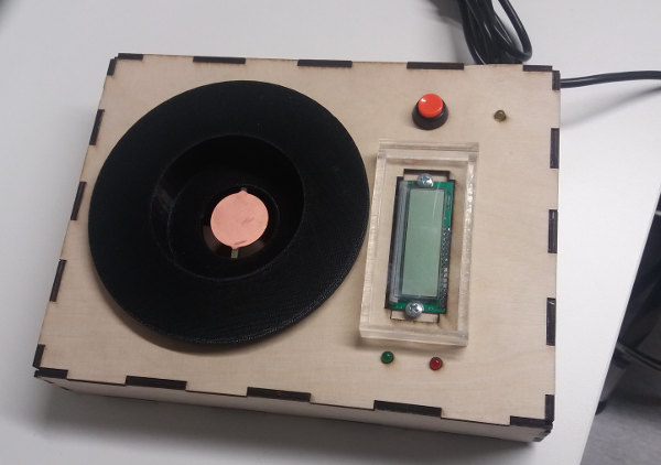
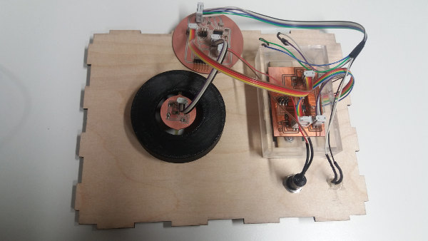
Electronics are inside the box.
The electronics are packed and connected for safety and proper functioning.
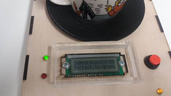
The system in use. Green led is on when coffee is perfect to drink. LCD dislays message and temperature estimate.
Yellow led shows that the system is powered on.
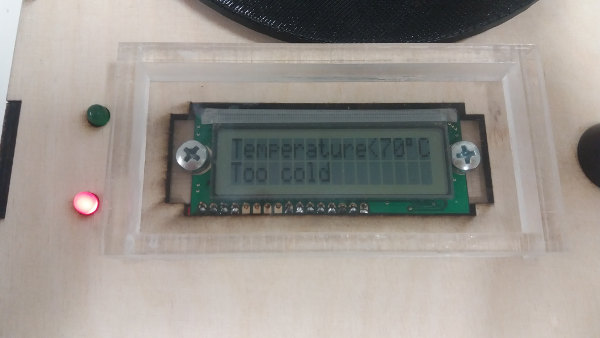
Red led is on when coffee is too cold or too hot. LCD dislays message and temperature estimate.
 What has not worked?
The final system does not display the exact temperature of the coffee because I did not find a way to convert the voltage into Celsius degress in the code for the ATtiny microcontroller. I have tried with float number and math library, but without success. I will explore this later as a future development of the system.
What questions still need to be resolved?The final project is successfully completed. However, for future improvements I plan to find the way to convert the voltage in Celsius in the microcontroller code if it is possible for this type of microcontroller.
What have I learned?This project was interesting and challenging. I have learned the following:
- to manage time and project so to deliver a final prototype product by the deadline with good quality.
- to program microcontrollers with C language and read and use information from datasheets.
- to design and fabricate physical parts using Solid Works, Autodesk Inventor Professional, laser cutter and 3D printing machines, and putting these parts together to make a functional prototype.
- to apply licenses and copyright for own projects.
- to manage version control using git.
Deliverables
PCB design files (Eagle files): LCD.sch; NTC.sch; Main_Board.sch; LCD.brd; NTC.brd; Main_Board.brd
CAD files (Inkscape): plywoodcase.svg; acrylic_screens.svg
CAD files (Solid Works): Part1.SLDPRT; Part2.SLDPRT; plate.SLDPRT; mugholder.sldprt; mugholder.SLDASM;mugholder.stl
Code files (.c files): LCD board; Main board
Detailed project execution
Detailed description of the project execution is on Final Project page.


