Study archive - Week 13
Output devices
The task of the week was to design a board that links an output device to a microcontroller and program it to do something.
I decided to add an LCD since I plan to use one in my final project. The first challenge was to design the LCD connections on the PCB; the LCD component is a module with own microcontroler and other components. The module component has 16 hole pins. The order of the pins is not sequential, but as follows 15, 16, 1, 2, 3, ... 14.
Learning about LCD pinoutLCD modules may have different pinouts. I have used an LCD Module for 16x2 characters from Lumex Opto/components, namely LCM-S01602DTR/M (see dataseheet)
PCB design
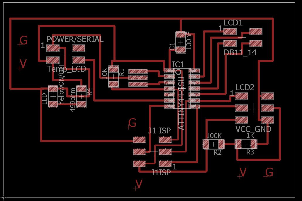
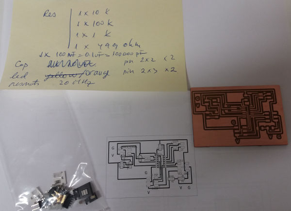
I have used Neil's board design as a starting point. I have added a led to indicate power connection and I separated the 10-pin connectors in two parts: a 2x2 pin header and a 2x3 pin header. The 2x2 header is used to connect the databus (DB) pins 11,12,13, 14 on the LCD to the microcontroller. The 2x3 header is used to connect the power, GND, Register signal (RS), and Enable (E) pins on the LCD to the microcontroller. I have not used a voltage regulator because I intend to power the board from PC via an FTDI cable.
I have used Attiny 44A as the microcontroller.
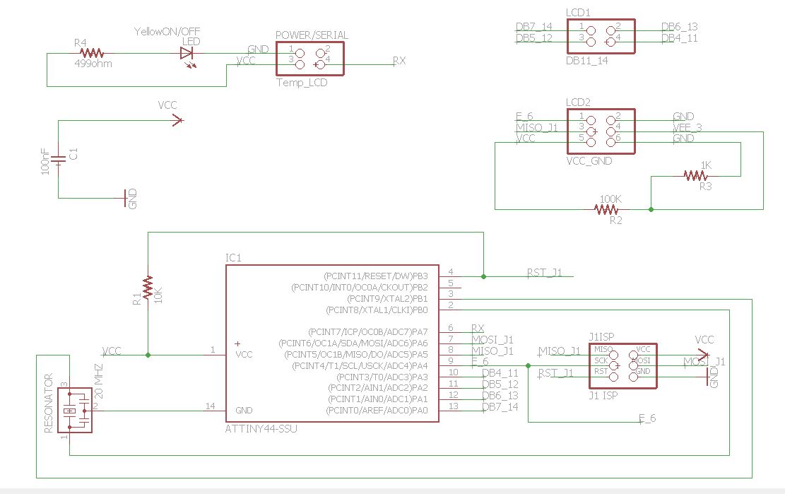
 The RX connection from the power pin header to the microcontroller is to be used further in the final project (see details on final project page).
Milling and Soldering
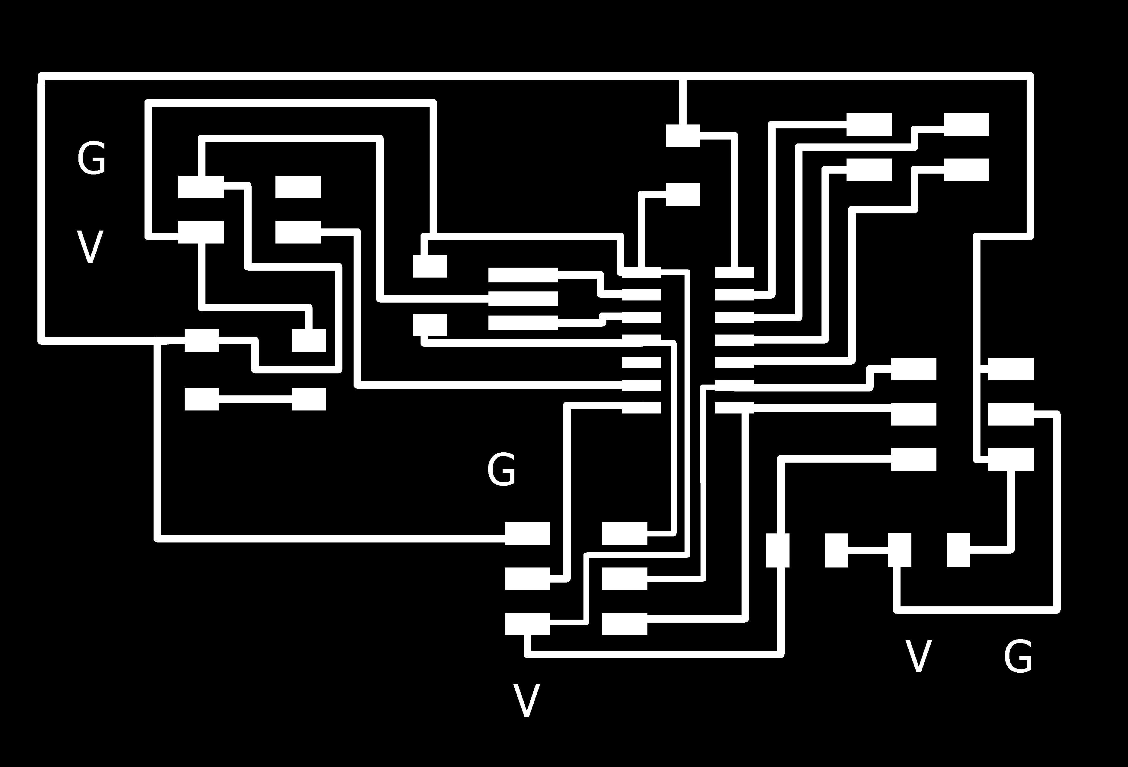
In GIMP, I have created the traces png image for milling
and the outline png image for milling

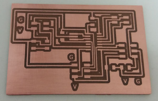
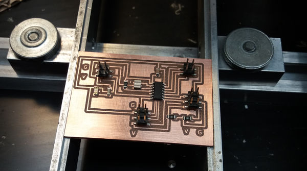
Next, I have used Fabmodules.org for creating the rml files that are needed to mill the traces and outline by the Rolland Milling Machine. The result of the milling is shown below. I have washed the PCB and sandpaper it to clean it.
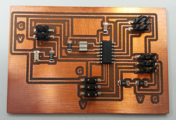
For soldering I have used the pick and place and the reflow oven.
Then I have added an LCD connector which I adapted from a FTDI connector type with 16 pins (by bending the yellow pins). The yellow pins are connected to the LCD and the silver pins to the wires to be connected to the ATtiny44A. Soldering the wires to the pins was quite difficult.
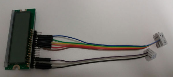
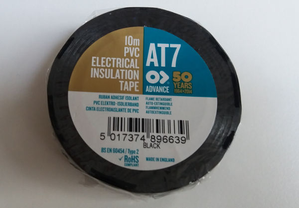
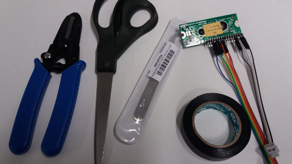
As shown in the picture, I have also used electrical insulation tape to isolate the wires among themselves. This step and the wiring itself add also to the consumables and process to be documented for the final project for the wiring and insulation.
Programming
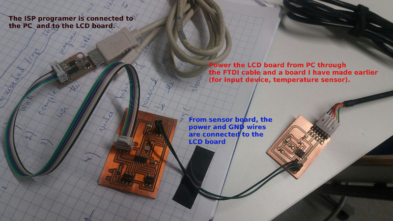
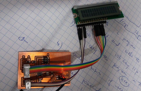
For programming to succeed it is important to connect correctly all the components. This means for example to pay attention to power and GND wires so that they are correctly placed (GND to GND and V to V). Use multimeter to check pins to make sure the connections are correct. The schematic of each board are needed to make the connections all right. In my case, the wiring is presented in the following pictures.
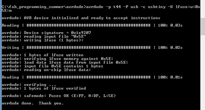
For programming, I have used the Neil's c code from FabAcademy page, lecture Output devices, LCD. I have compiled and built the .hex file in Atmel Studio. Then I have used AVRDUDE program in Windows command line (cmd.exe) to program the ATTiny44A.
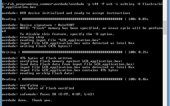
I have set the low fuses to the correct value for the 20 MHz clock.
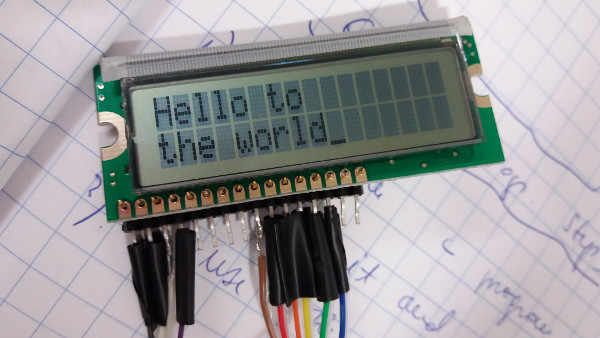
To see the program in action, the pcb has to be powered and the LCD has to be correctly connected to the pcb. The led light in the picture below shows that the pcb is powered.
When powered, notice also the text on the LCD screen.
Summary of the week
The task of this week are useful for the final project. Additional programming of the LCD will be described in the final project page.
Summary of Tools used
Software
Eagle
Atmel Studio C
AVRDUDE
GIMP
Hardware
Rolland Milling
Soldering machines: pick and place and reflow oven; electronics workbench for manual soldering


