On this page you can follow all the steps that I’ve been given to reach the final result. The Interactive showroom.
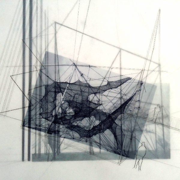
I worked with the idea of having mobile spaces making possible new forms of artistic creativity in the furniture exhibition. This space is enabled so that designers, scenographers, artists… etc. can develop their exhibition creativity combining all the artistic fields.
It is conceived as a multipurpose space where the furniture is the main subject. For this, a light support structure has been created in which different daydreams and sets are hanged. Punctual motors in specific points are used allowing us to create different spatial configurations that make the observer being participant of that set. It is be a mobile territory in which it is impossible to have similar experiences.
3D Design - Computer Aided design
2D Design- Computer Aided design
Boards Design - Networking and comunications
Regulator Board - Networking and comunications
Sensor Board - Networking and comunications
Motor Board - Output Devices
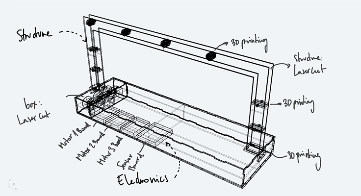
The first thing I did was thinking about how my project's structure should be and then I did some sketches of how it would work better. The principal concern was creating a hoist system and how I was going to support it so I thought about doing a very simple acrylic arch on top of a basement
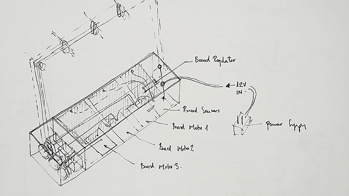
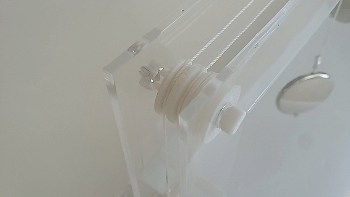
Taking into account that the hoist system would consist of three stepper motors attached to a string I considered that the best option for allowing the vertical movement was transmitting it through a system of pulleys. These pulleys would be place on the upper part of the arch.
I designed each element of the system: the pulleys and how they were going to be placed in the structure. I thought about separating the hook and the pulley to allow its rotatory movement. It is a very a very simple way in which an elongated piece goes through the pulley and prevents it from falling down due to the geometry of this piece.
Union
Pulley
Union + Pulleys
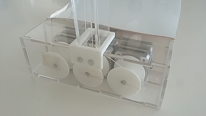
I also was very concern about how I was going to be able to transmit the movement from the motors to the string. It had to be a piece that could keep a certain size of the string and that moves at the same time as the motor. I decided to base this piece in the sewing machines and its bobbin. I designed a pieces that would work as the bobbin that fit together exactly with the motor.
Bobbin
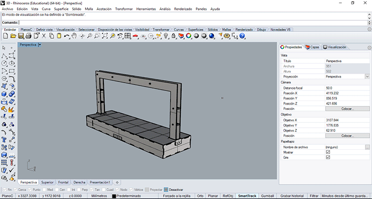
I also designed the pieces that give toughness to the structure and that allows the different strings coming from the motors pass through them. For the 3d design I used Rhinoceros because it’s the best modelling program. You can observe in the 3d model the different parts that it has.
Support pieces
Connection pieces basement-support
The final 3d model
For the 3d design I used Rhinoceros because it’s the best modelling program. You can observe in the 3d model the different parts that it has.
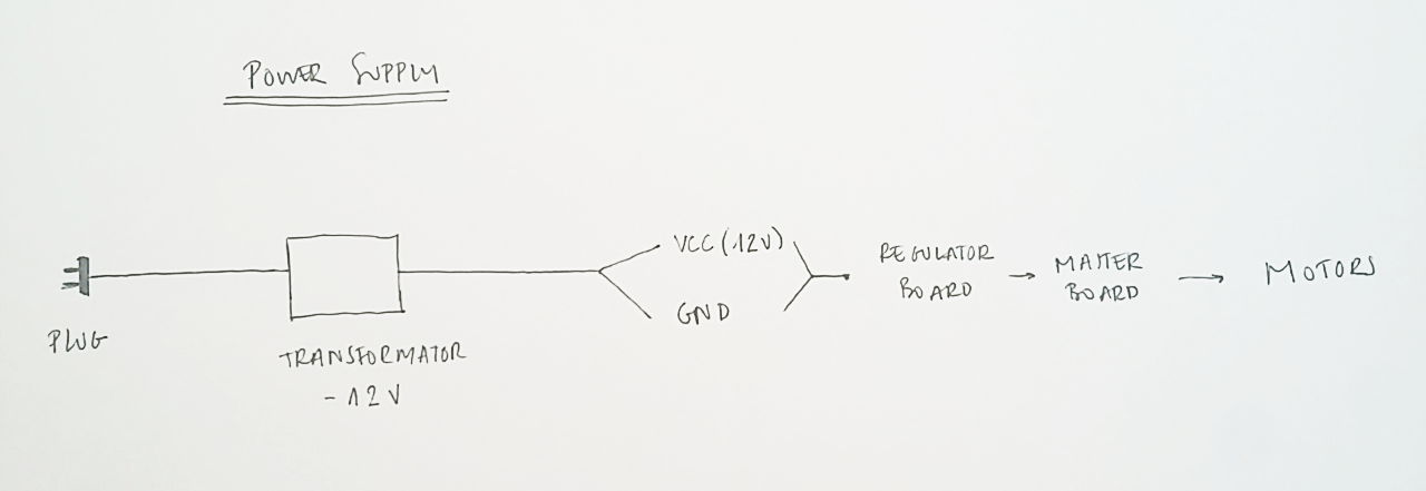
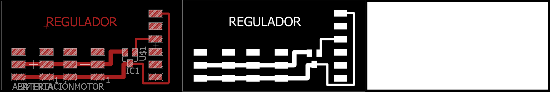
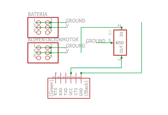
I needed to use a different power supply than the computer one because the motors use 12V. I also had the regulator board that I fabricated on the Output devices assignment so I used this regulator for my final project. The idea was to connect 12V to the regulator board and to the motor boards. Then the regulator board reduces from 12V to 5V because the microcontrollers work at 5V and these 5V goes to each board through the I2C connection. For the power supply I used one that was in my Fab Lab. It was a 12V and 1A. I cut the wire and identify which one was GND and wich one was VCC to connect them to the regulator board.
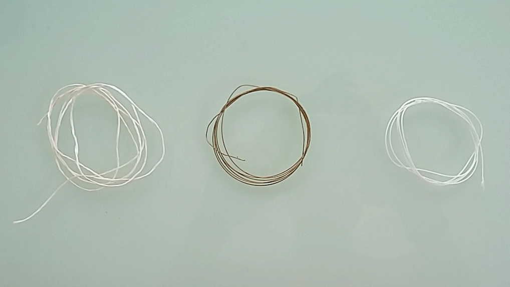
Selecting the correct string was very important because not all strings are the same and work well. I found another type of string that is used for bookbinding. This string is strong enough to support things hanging from it and its movement is very smooth when the string is stretch. . In the following picture at the left is the generic string I used first, in the middle the metallic one and in the right the one I finally used, the one that worked better.
Once I knew how I wanted my final project to be, the next step was to designing it in the computer with its real measures and start doing the cut plans. Before cutting the final structure I did a prototype in MDF in order to see if everything that I designed worked well. I tested the MDF prototype and ot worked well so I cut the pieces but this time in acrylic. I used Autocad for the plans design.
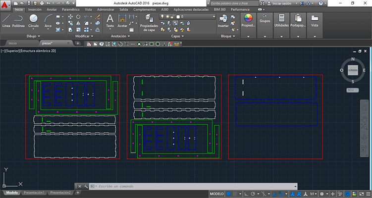
As the MDF prototype was working I decided to do the final model: the one in acrylic. I also did some lasercut tests in order to see the tolerances, but this time I used different parameters. As I had to cut acrylic I used a low power and a slow speed because I didn’t want the laser to be reflected on the metal bars that are used hold the acrylic sheet.
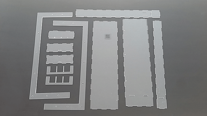
In the video we can see how the sheets were cut with the lasercut.
lasercut1 from msantisteban on Vimeo.
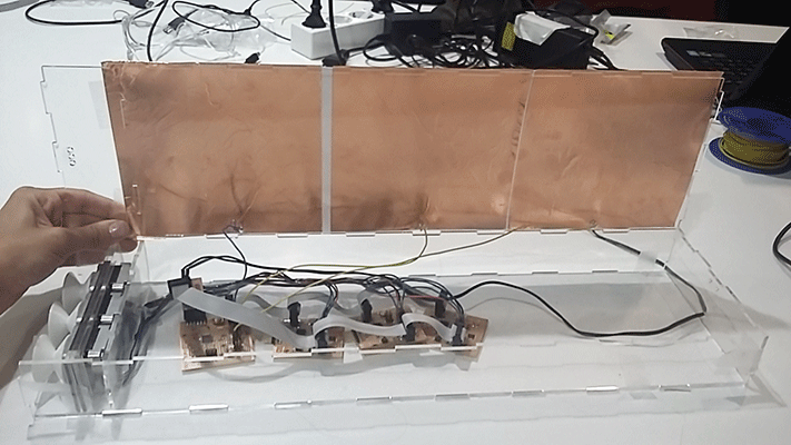
I assemble all the different pieces in order to have the real structure in acrylic with all its 3d printed parts:
In the following video you can apreciate how is the final result and each part of the structure
final2 from msantisteban on Vimeo.
I did the regulator Board in the Output devices assignment.
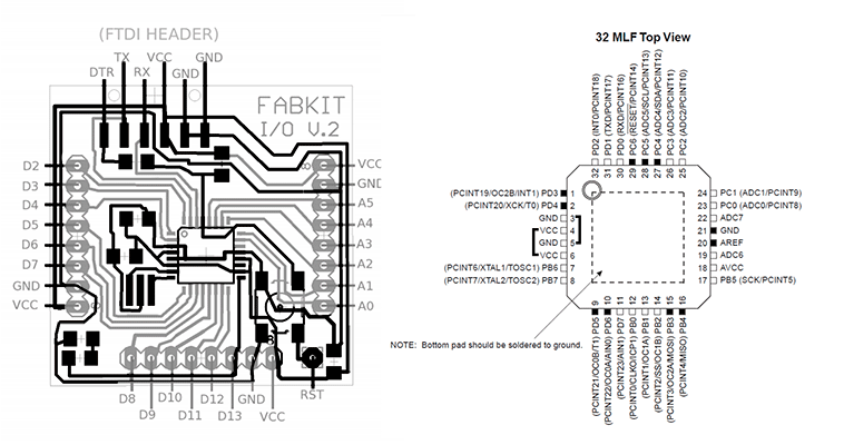
As I wanted to use the Arduino libraries (wire: master writer, master reader) and this library is not working with AtTiny 44/45 I decided to use the same processor that the Fabkit, an ATMega168 . I based the design of my motor board in the Fabkit, I erased all the elements that I didn’t need and I added the ones that my board needed, in my case I added:
• 6 pin header for programming (GND, RST, MOSI, SCK, MISO,VCC)
• 6 pin header for 12V power (VCC, VCC, GND, GND) As I did in the output assignment I only needed 4 pins but I used a 6 pin header just in case I connected in a wrong position the header in order to not breaking the board.
• 4 pin connector I 2 C (SCL, GND, SDA, VCC)
• 2 H-Bridge
With the aid of the datasheet the next step was seeing where I had to connect all this new things in the microcontroller. First of all I thought to connect my motors to the analog pins as in the output assignment (PINS 28,27) but I realize I couldn’t because these pins where needed to connect SCL and SDA so I had to connect the motors to another pins (PINS 1,2,9,10). As I put a 6 pin header for the procreation I needed to connect MISO and MOSI to its respective pins in the microcontroller.
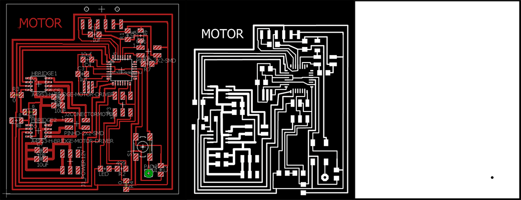
As I wanted to mix both boards the Fabkit board and the one I made in the Output assignment I used the Eagle files. As I said before, I cleared all the elements I didn’t need and add the ones I needed and then I connected them to its pins. It was the hardest board I’ve done till the moment and I founded very difficult to put and connect every single element but at the end I was able to do it!
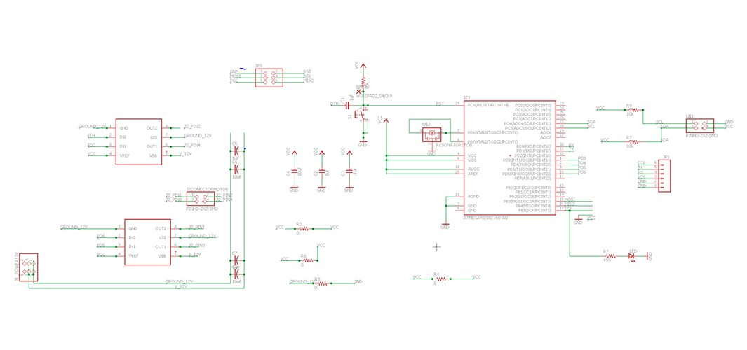
As I wanted to do three boards there were a lot of elements so I had to be very organised in order not to lose some elements.
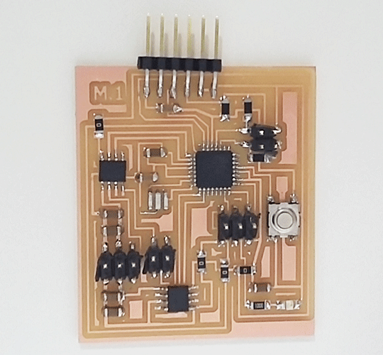
After checking that all the wiring in my new board was correct I program it with Arduino burning the bootloader. For this I had to connect my FabISP to my board.
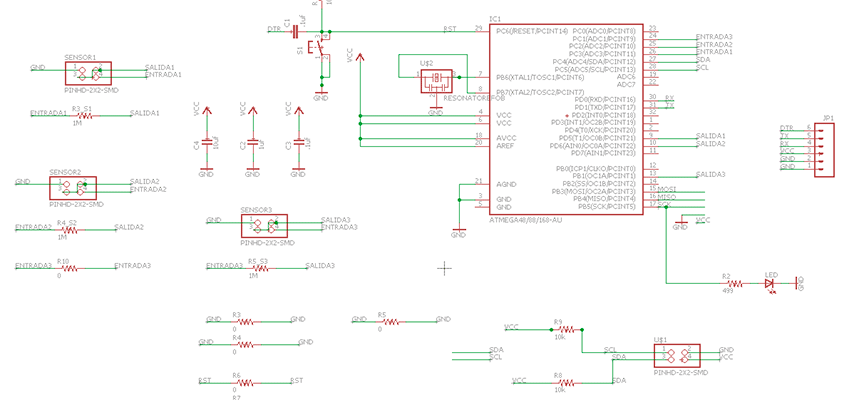
As my final project has three different motor systems activated by three sensors I did a board in which I connected the sensors. I designed the board with Eagle and with the aid of the datasheet of the microcontroller I connected the sensors to it. The capacitive sensor needs two pins: one analog pin for the entrance and another digital pin for the exit.
I connected the sensors to the microcontroller to PC1, PC2 and PC3 for the entrance pins and PD5, PD6 and PB1 for the exit pins.
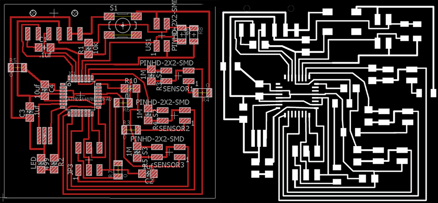
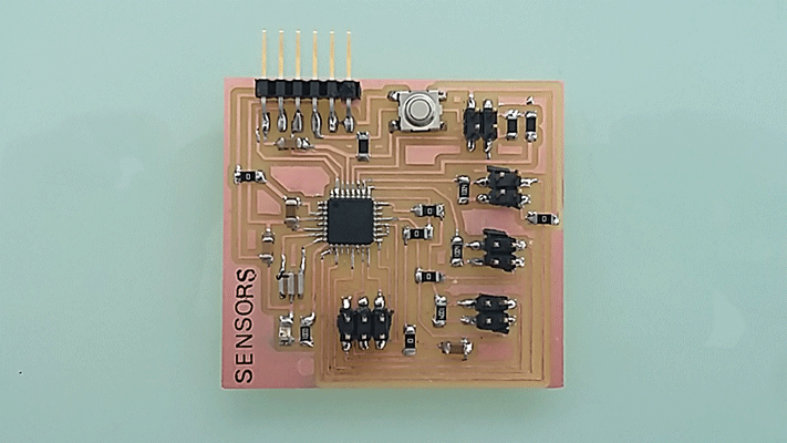
After milling the board I programmed it with my FabISP burning its bootloader with Arduino.
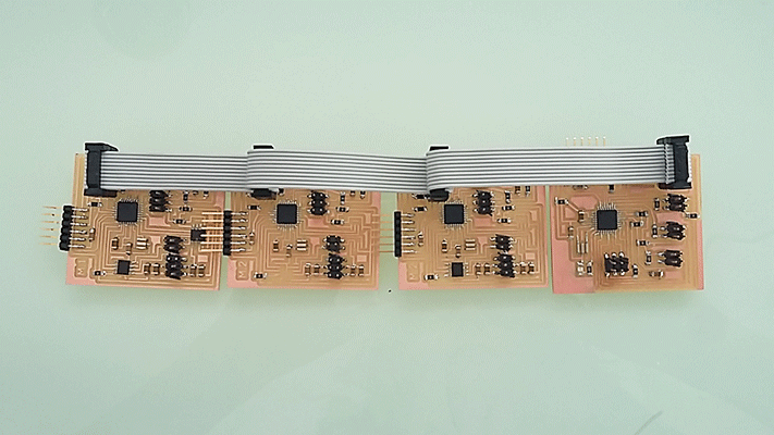
I did all the wiring between the 4 boards with a pain wire in order to establish a communication between them. When I finished doing the wiring I started programming the master board and the slave ones. I decided the sensor board to be the master board because this way the sensor board receives information from each sensor and it sends the information to the slave boards that will be the motor boards.
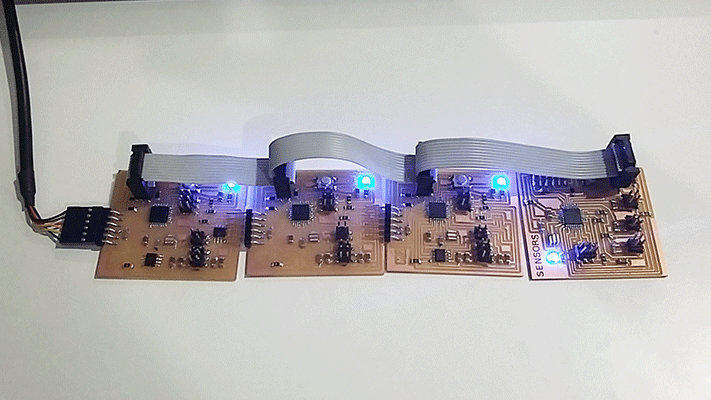
I started programming the four boards with each sketch. I did two different sketches: one for the sensor board that worked as de Master and another for the slave boards (the motor ones). I gave the same direction to the slave boards (wire begin(1)) because I only had one sensor. This way only one sensor was connected to the master board and when this received changes from the sensor, it sends to all the slaves to turn on its led so the four leds turned high and to move each motor.
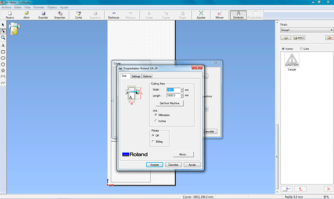
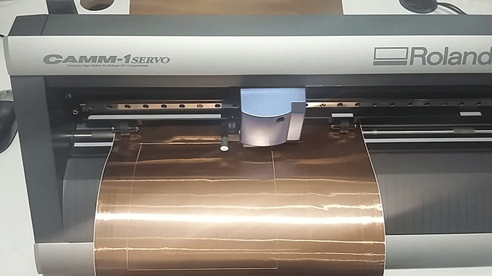
I did the final sensors with the vinyl cutter using copper vynil. I had to do some tests in order to see which parameters were the best for this material and at the end I reached the conclusion that its parameters were: 3cm/s speed and 120gf of strength. These parameters are different that the ones used for the normal vinyl, I slower the speed and put more strength for the copper.
cutting the sensors from msantisteban on Vimeo.
Them I soldered the wires to the sensors and connected them to the sensor board. I put the sensors in its place.
In the following video you can apreciate that the final sensors worked well with the last Arduino sketches.
sensors test from msantisteban on Vimeo.
I covered these sensors with white vynil so that you couls not see the copper.
All the electronics are based on Networking and Communications between boards though I2C. I considered having 4 different boards connected between them. These boards were designed and programmed in the Networking and Communication assignment. In this assignment I designed the motor boards and checked if they worked well moving the motors, I also designed the sensor board with three different sensors and I could check that they worked also well.
This is a scheme of how the electronics works.
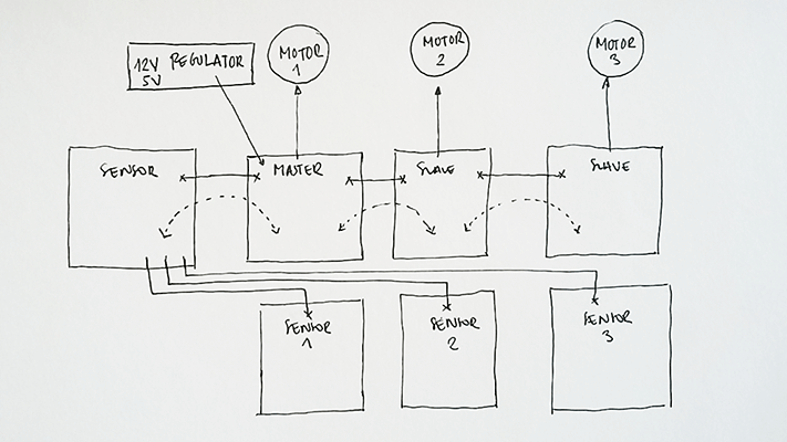
The sensors board: is receiving data from three different sensors. This board will be acting as the Master board because this way it can send the data through I2C to the slave boards.
The motor boards (X3): these boards are receiving data from the master board. These boards give orders to the motors. When to move and when to stop.
So far I had been testing the sensors with LEDs boards as the output in the Networking and communications assignment but I wanted to put together the sensors and the motors so I started to do another Arduino sketch: I used the same Master sketch but I updated the Slave one, instead of turning on and off the LED board I added the motor movement:
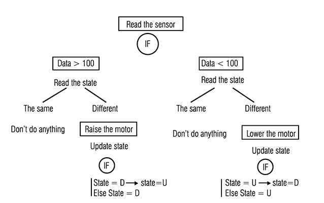
After doing the final sensors I had to do the final sketch for my final project because the one I had wasn’t the final program I wanted to use. I did a scheme of how I wanted the program to be and what I added was giving a state to the motor: when the motor is down its state is “D” and when the motor is up its state is “U” and every time there is a change in the values of the sensor this state changes. This is the program scheme:
//Mastertressensores:


#include <CapacitiveSensor.h>
#include <Wire.h>
CapacitiveSensor   cs_5_17 = CapacitiveSensor(5,17);
CapacitiveSensor   cs_6_16 = CapacitiveSensor(6,16);
CapacitiveSensor   cs_9_15 = CapacitiveSensor(9,15);
void setup() {
cs_5_17.set_CS_AutocaL_Millis(0xFFFFFFFF);     // turn off autocalibrate on channel 1 - just as an example
cs_6_16.set_CS_AutocaL_Millis(0xFFFFFFFF);     // turn off autocalibrate on channel 1 - just as an example
cs_9_15.set_CS_AutocaL_Millis(0xFFFFFFFF);     // turn off autocalibrate on channel 1 - just as an example

Serial.begin(9600);
Wire.begin(); // join i2c bus (address optional for master)
pinMode(13, OUTPUT);

}
byte x = 0;

void loop() {
  // read the sensor:
  long total1 =  cs_5_17.capacitiveSensor(30);
  long total2 =  cs_6_16.capacitiveSensor(30);
  long total3 =  cs_9_15.capacitiveSensor(30);

      if (total1 > 99){
        x = 1;
        digitalWrite(13,HIGH);
        Wire.beginTransmission(1); // transmit to device #1
        Wire.write(x);              // sends one byte
        Wire.endTransmission();    // stop transmitting
        Serial.println(x);
       }
     else{
       digitalWrite(13,LOW);
        x = 0;
        Wire.beginTransmission(1); // transmit to device #1
        Wire.write(x);              // sends one byte
        Wire.endTransmission();    // stop transmitting
        Serial.println(x);
       }


       if (total2 > 99){
        x = 1;
        digitalWrite(13,HIGH);
        Wire.beginTransmission(2); // transmit to device #2
        Wire.write(x);              // sends one byte
        Wire.endTransmission();    // stop transmitting
        Serial.println(x);
       }
     else{
       digitalWrite(13,LOW);
        x = 0;
        Wire.beginTransmission(2); // transmit to device #2
        Wire.write(x);              // sends one byte
        Wire.endTransmission();    // stop transmitting
        Serial.println(x);
       }

       if (total3 > 99){
        x = 1;
        digitalWrite(13,HIGH);
        Wire.beginTransmission(3); // transmit to device #3
        Wire.write(x);              // sends one byte
        Wire.endTransmission();    // stop transmitting
        Serial.println(total3);
       }
     else{
       digitalWrite(13,LOW);
        x = 0;
        Wire.beginTransmission(3); // transmit to device #3
        Wire.write(x);              // sends one byte
        Wire.endTransmission();    // stop transmitting
        Serial.println(total3);
       }

}
Slave Sketch
// Slavemotor


#include <Stepper.h>
#include <Wire.h>
const int stepsPerRevolution = 200; //steps in a revolution
volatile int y = 0;
Stepper myStepper(stepsPerRevolution, 3, 4, 5, 6); //motor pins

void setup() {
  Wire.begin(3);                // join i2c bus with address #1
  Wire.onReceive(receiveEvent); // register event
  myStepper.setSpeed(60); // set the speed at 60 rpm:
  pinMode(13,OUTPUT);
}

void loop() {


if (y==1){
myStepper.step(stepsPerRevolution); // step one revolution  in one direction:
myStepper.step(-stepsPerRevolution); // step one revolution  in one direction:
y=0;
}


}

// function that executes whenever data is received from master
// this function is registered as an event, see setup()
void receiveEvent(int hola){
volatile int x = Wire.read();    // receive byte fom wire

if (x==1){
digitalWrite(13,HIGH);
y=1;

}
else{
digitalWrite(13,LOW);
}
}
final1 from msantisteban on Vimeo.
presentation from msantisteban on Vimeo.
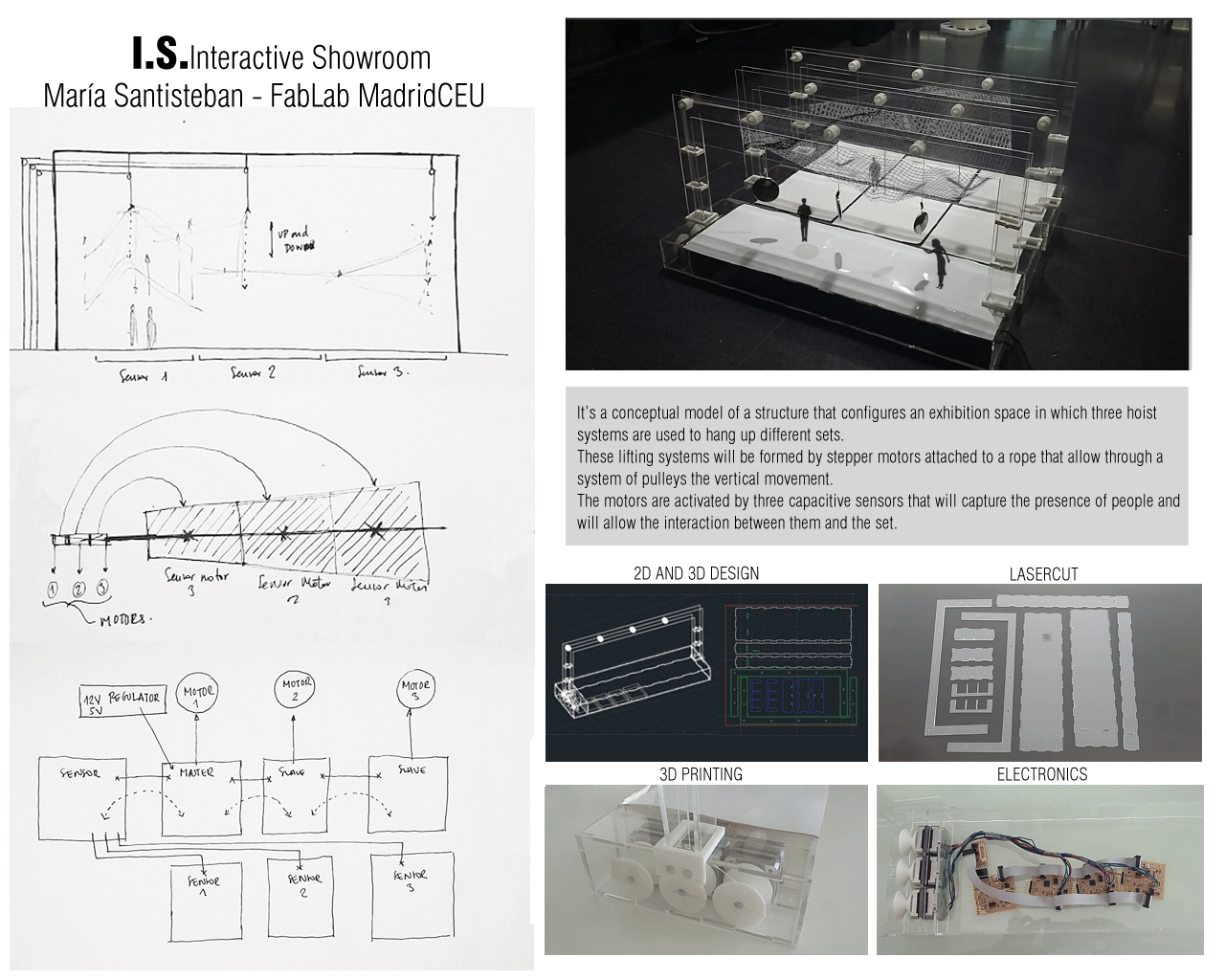
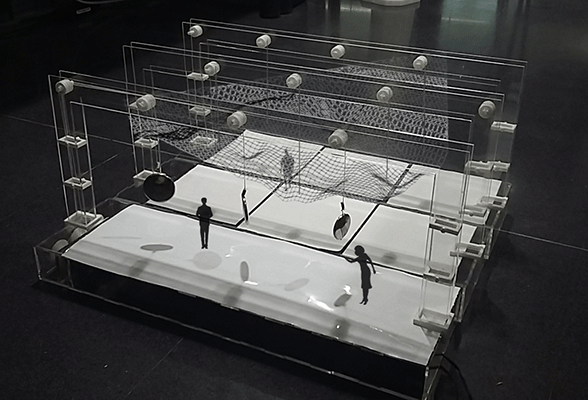
I did a conceptual model of a structure that configures an exhibition space in which three hoist systems are used to hang up different sets. These lifting systems are formed by stepper motors attached to a rope that allow through a system of pulleys the vertical movement. The motors are activated by three capacitive sensors that capture the presence of people and will allow the interaction between them and the set.
What does it do?
My final project is a prototype that serve to understand how a space for a showroom is conceived. It shows a system for multipurpose space where the furniture is the main subject. For this, a light support structure has been created in which different daydreams and sets are hanged. Punctual motors in specific points are used allowing us to create different spatial configurations that make the observer being participant of that set. It is a mobile territory in which it is impossible to have similar experiences.
Who has done what beforehand?
What I wanted to capture in my final project is architecture capable of absorbing the impact of various artistic languages. I wanted to create a multilingual contemporary design lab opened to the influences that come from different levels of the culture. For creating this, I’ve been inspired by the theatre spaces and its machinery because in the end my final project works as a stage but with the difference that what I’m creating is a scene meant to be seen from all points of views not just one as the theatres.
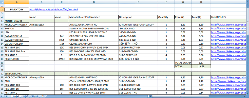
What materials and components will be required? Where will they come from? How much will it cost?
For answering these three questions I’ve done an inventory excel file in which it specifies all the components my final project has including all the electronics components, the motors, and the different materials for the structure and the hook system. It is also specified how much it cost each material and where can be bought. All the components of my final project are found in the fabacademy inventory.
The structure is made of mathacrylate, this material helps to give a sense of lightness to the structure and allows see all the electronics and motors inside. The hook system is printed with white PLA
What parts and systems are made? What processes are used?
I divided the work into three groups: Structure, hook system and electronics. The structure is made with the laser cutter machine, the hook and hoist system is printed in PLA, and the boards aremilled with the Rolland modela, the vinyl cutter is used for cutting the copper vinyl for the sensors
What worked, and what didn’t? What questions still need to be resolved?
Although I had some problems with the electronics and with the motors I could manage to do a final project that worked well but some tasks can be improved:
Motors: When I press all the sensors and then I stop pressing them the third one continues vibrating but doesn’t move. I still don’t know what’s the problem maybe is the power supply but the power still reaches the motors even if I don’t press the sensor. In the following video you can apreciate how the last motor when I stop pressing the sensor still make a noise.
sensors and motors from msantisteban on Vimeo.
Pulleys: The design of the pulleys work well but it can be improved, the connection between them and the acrylic structure.
Programming: The programming needs to be improved in order to have a better interaction. I wanted each sensor to activate a motor and I did it but i think it can be improved if each sensor interacts with all the motors.
What is the deadline? How much time do I have left?
The deadline was June 22th; I organized all the work in order to finish it the 21th. As a very big part of my final project was networking and communications between the boards I worked a lot on the weekly assignment so I had a week to do the structure and to conclude the final programming for the 17th. I dedicate the days before the final presentation (20-21th) to do the final video and slide.
What tasks have been completed, and what tasks remain?
All the tasks have been completed but as my final project is a prototype for a project that I’m working on for University I have in mind to continue working on it. At the moment I have three structures but only one is working with the electronics so I only reached to have “linear” results. I would like to implement the remaining structures with its electronics in order to have different configurations in the space, not just in 2d as I have at the moment.
What you learned?
Doing the final project an in general, doing the Fabacademy I’ve learned a lot. I’ve learned the different materials I can work with the laser cutter machine and with the 3d printer. I also learned a lot of Arduino and programming spatially networking and communications. For me it has been a challenge doing the final project because when I started Fabacademy I didn’t know anything of electronics and now I’m able to design electronic boards!
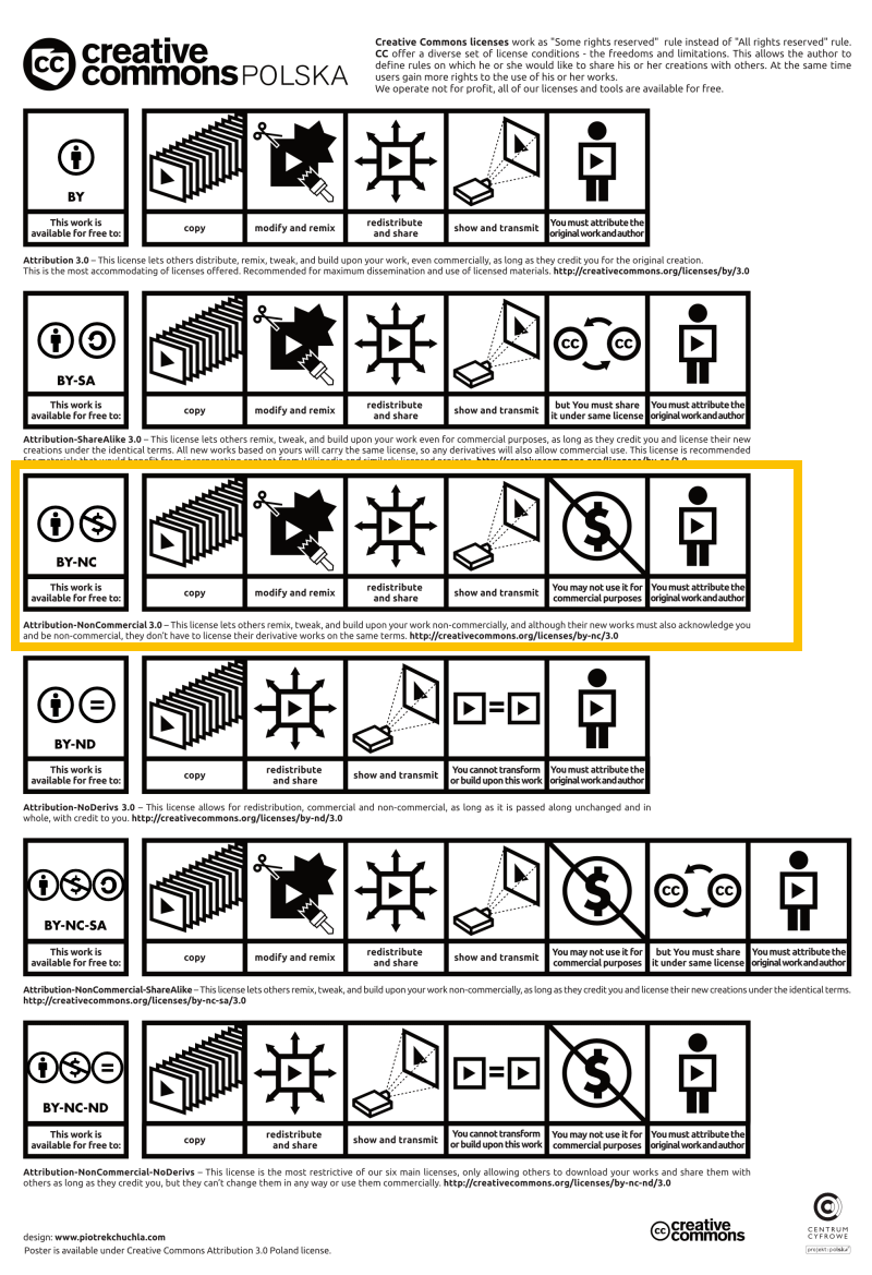
After reading all the documentation about the different types of licenses I decided to use for my final project the Creative Commons license because I think is the best option. It is a perfect license I want to reach the largest number of developers and I do not care so much where or how can use my project. It does not guarantee freedom of the application.
These are the different licences that Creative commons offers you. I selected the Attribution-NonCommercial-ShareAlike 4.0 International
Attribution: You must give appropriate credit, provide a link to the license, and indicate if changes were made. You may do so in any reasonable manner, but not in any way that suggests the licensor endorses you or your use.
NonCommercial: You may not use the material for commercial purposes.
ShareAlike: If you remix, transform, or build upon the material, you must distribute your contributions under the same license as the original.
No additional restrictions: You may not apply legal terms or technological measures that legally restrict others from doing anything the license permits.

Este obra está bajo una licencia de Creative Commons Reconocimiento-NoComercial 4.0 Internacional.
PLAN FOR DISSEMINATION
My final project is a prototype of an architecture space for a showroom; is a project that I’m working at University. The goal for it is to be constructed someday. At the moment I have the idea and I’m working on how it would be constructed in real life with all the constructive details and all the structural calculations. It would be a good idea when all the investigation is finished and all the documentation is viable for constructing it to look for investors or other founding possibilities such as Government associations, crowd funding, cultural and artistic associations, international enterprises...etc that are interested on making the project come to reality. Also a business plan must be designed with a management team made of engineers and architects in order to sell the idea in a better way.
STRUCTURE
2D Design
3D Design
ELECTRONICS
Regulator Board
Sensor Board
Motor Board
PROGRAMING
Master Sketch
mastertressensoresidavuelta2 (.ino)
Slave Sketch