The aim for this week’s assignment was to write and application that interfaces with an input &/or output. I really founded very interesting to do an application for my final project, as I am working with stepper motors I thought to do an interface that can give instructions of movements to them but first as this was my first programming an application I wanted to know how the basics examples work in order to be able to program a more complicated application.
First I thought to start programming an input; in this case I chose the board that I did in the input devices assignment because this board has a button, a led and the processer is the same that I using for the stepper motors: the ATMega168
READING AN INTPUT IN PROCESSING
I chose working with processing because it gives you the possibility to work with Arduino at the same time, and in the examples programs processing also has the examples for Arduino and vice versa. For me this was the best option because I am working with Arduino all the time.
I wanted to start working with the communication between Arduino and Processing. It was my first time programming in processing so what I did was starting with a very simple sketch of the principal libraries (simple read). Processing has good thing because in the examples it gives you also the Arduino program so it is very simple to get that example and modify it in Arduino with our pins so that’s what I did.
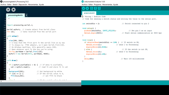
The simple read example was very simple and I decided to complicated a bit more changing the color of the square. I wanted the square to turn blue by pressing the button. 2 different sketches are needed in order to do this: first of all, the Arduino sketch must be loaded in our board in order to communicate it with the serial port and then the processing sketch reads the data coming through the serial port and converts it into a drawing, in this case a rectangle becoming blue or gray.
Processing sketch
import processing.serial.*;

Serial myPort;  // Create object from Serial class
int val;      // Data received from the serial port

void setup()
{
  size(200, 200);
  // I know that the first port in the serial list on my mac
  // is always my  FTDI adaptor, so I open Serial.list()[0].
  // On Windows machines, this generally opens COM1.
  // Open whatever port is the one you're using.
  String portName = Serial.list()[0];
  myPort = new Serial(this, portName, 9600);
}

void draw()
{
  if ( myPort.available() > 0) {  // If data is available,
    val = myPort.read();         // read it and store it in val
  }
  background(255);             // Set background to white
  if (val == 1) {              // If the serial value is 0,
    fill(0,0,255);                   // set fill to blue
  }
  else {                       // If the serial value is not 0,
    fill(204);                 // set fill to light gray
  }
  rect(50, 50, 100, 100);
}
Arduino sketch
	// Wiring / Arduino Code
// Code for sensing a switch status and writing the value to the serial port.

int switchPin = 2;                       // Switch connected to pin 2

void setup() {
  pinMode(switchPin, INPUT_PULLUP);             // Set pin 0 as an input
  Serial.begin(9600);                    // Start serial communication at 9600 bps
}

void loop() {
  if (digitalRead(switchPin) == LOW) {  // If switch is ON,
    Serial.write(1);               // send 1 to Processing
    digitalWrite(10,HIGH);
  } else {                               // If the switch is not ON,
    Serial.write(0);               // send 0 to Processing
    digitalWrite(10,LOW);
  }
  delay(50);                            // Wait 100 milliseconds
}
input+output processing1 from msantisteban on Vimeo.
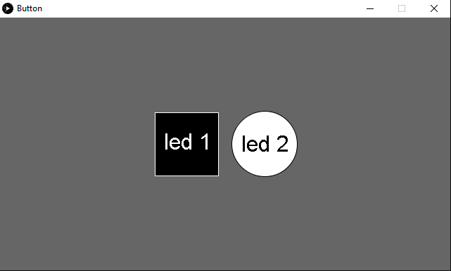
READING AN OUTPUT IN PROCESSING
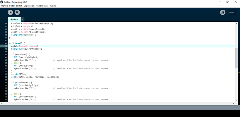
After doing the simple sketch of reading an input I decided to do another sketch more complicated. I wanted to check the communication between the different boards that I will use in my final. Processing will activate each led board whenever I am over the circle or the rectangle. For doing the different sketches I used the button example from processing and the wire library for Arduino.
First of all, I did the Arduino programs modifying the serial read because I wanted processing to send actions to the serial port and then the master board read these actions and activate whether the master board led or the slave board led (circle or rectangle).
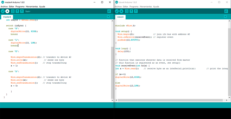
Arduino master sketch
#include
void setup() {

Serial.begin(9600);
Wire.begin(); // join i2c bus (address optional for master)
pinMode(13, OUTPUT);

}
byte x = 0;

void loop() {
  // read the sensor:
  if (Serial.available() > 0) {
    int inByte = Serial.read();

    switch (inByte) {
      case 'H':
        digitalWrite(13, HIGH);
        break;

      case 'L':
        digitalWrite(13, LOW);
        break;

      case 'E':

        Wire.beginTransmission(2); // transmit to device #2
        Wire.write(x);              // sends one byte
        Wire.endTransmission();    // stop transmitting
        x = 1;

      case 'A':

        Wire.beginTransmission(2); // transmit to device #2
        Wire.write(x);              // sends one byte
        Wire.endTransmission();    // stop transmitting
        x = 0;

        }
    }
  }
Arduino slave sketch
// Wire Slave Receiver


#include

void setup() {
  Wire.begin(2);                // join i2c bus with address #8
  Wire.onReceive(receiveEvent); // register event
  pinMode(13,OUTPUT);
}

void loop() {
  delay(100);
}

// function that executes whenever data is received from master
// this function is registered as an event, see setup()
void receiveEvent(int hola) {
int x = Wire.read();    // receive byte as an inteSerial.println(x);         // print the integer

if (x==1)
digitalWrite(13,HIGH);

else
digitalWrite(13,LOW);
}
Processing sketch
/**
 * Button.
 *
 * Click on one of the colored squares in the
 * center of the image to change the color of
 * the background.
 */
import processing.serial.*;

Serial myPort;  // Create object from Serial class
int val;        // Data received from the serial port

int rectX, rectY;      // Position of square button
int circleX, circleY;  // Position of circle button
int rectSize = 90;     // Diameter of rect
int circleSize = 93;   // Diameter of circle
color rectColor, circleColor, baseColor;
color rectHighlight, circleHighlight;
color currentColor;
boolean rectOver = false;
boolean circleOver = false;

void setup() {

  size(640, 360);
  String portName = Serial.list()[0];
  myPort = new Serial(this, portName, 9600);
  rectColor = color(0);
  rectHighlight = color(51);
  circleColor = color(255);
  circleHighlight = color(204);
  baseColor = color(102);
  currentColor = baseColor;
  circleX = width/2+circleSize/2+10;
  circleY = height/2;
  rectX = width/2-rectSize-10;
  rectY = height/2-rectSize/2;
  ellipseMode(CENTER);
}

void draw() {
  update(mouseX, mouseY);
  background(currentColor);

  if (rectOver) {
    fill(rectHighlight);
    myPort.write('H');              // send an H to indicate mouse is over square
  } else {
    fill(rectColor);
    myPort.write('L');              // send an H to indicate mouse is over square
  }
  stroke(255);
  rect(rectX, rectY, rectSize, rectSize);

  if (circleOver) {
    fill(circleHighlight);
    myPort.write('E');              // send an H to indicate mouse is over square

  } else {
    fill(circleColor);
    myPort.write('A');              // send an H to indicate mouse is over square

  }
  stroke(0);
  ellipse(circleX, circleY, circleSize, circleSize);
}

void update(int x, int y) {
  if ( overCircle(circleX, circleY, circleSize) ) {
    circleOver = true;
    rectOver = false;
  } else if ( overRect(rectX, rectY, rectSize, rectSize) ) {
    rectOver = true;
    circleOver = false;
  } else {
    circleOver = rectOver = false;
  }
}

void mousePressed() {
  if (circleOver) {
    currentColor = circleColor;
  }
  if (rectOver) {
    currentColor = rectColor;
  }
}

boolean overRect(int x, int y, int width, int height)  {
  if (mouseX >= x && mouseX <= x+width &&
      mouseY >= y && mouseY <= y+height) {
    return true;
  } else {
    return false;
  }
}

boolean overCircle(int x, int y, int diameter) {
  float disX = x - mouseX;
  float disY = y - mouseY;
  if (sqrt(sq(disX) + sq(disY)) < diameter/2 ) {
    return true;
  } else {
    return false;
  }
}
Interface and Application programming from msantisteban on Vimeo.
FILES:
Input:
communicationarduinosketch (.ino)
Output: