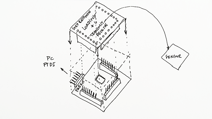
This week’s assignment was creating a board for an input. As I was very interested on introducing the step response sensor on my final project, I decided to create a board with the two types of step response sensor: (loading + transmit-receive). I decided also to create the sensor board as a part of my Fabkit Arduino board that I did on the embedded programming assignment because this way I could use my Fabkit for other inputs in the future. Also I decided to put a LED as an output to see that my sensor is working without using the serial monitor. I also added a button on my sensor board in order to practice the external interruptions of the processer.
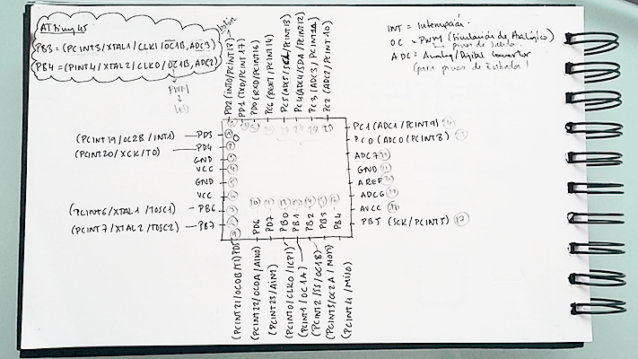
First of all what I did was with the help of the microcontroller datasheet, in my case the ATMega168 I did a very simple scheme showing all the pins and its functions of the processer in order to know where do I had to connect my sensors. All the pins were connected to one pin of the three 8 pin headers so I had to see which one was the correct one.
ANALOG PINS: (Sensors)
As the two types of the step response sensor work with analog pins, I looked in the datasheet which pins in order to connect my sensors to them. As I needed 2 analog pins for the two sensors I didn’t have trouble with that because the microcontroller had 4 analog pins.
Number pin 25: PC2 (ADC2/PCINT10) connected to A2.
Number pin 26: PC3 (ADC3/PCINT11) connected to A3.
Number pin 27: PC4 (ADC4/SDA/PCINT12) connected to A4.
Number pin 28: PC5 (ADC5/SC1/PCINT13) connected to A5.
PULSE WIDTH MODULATION: (LED)
As the Arduino board had a LED I had to see to what pin was connected to in order to connect the LED of my sensor board to another PWM pin. These pins are in the datasheet with the OC function. As the Arduino LED was connected to D13 I had to select another one:
Number pin 17: PB5 (SCK/PCINT5) connected to D13.
Number pin 14: PB2 (PCINT2/SS/OC1B) connected to D10.
INTERRUPTIONS: (Button)
As I wanted to practice with the external interruptions of the ATMega microcontroller I had to connect my button to a pin with the function INT:
Number pin 32: PD2 (INT0/PCINT18)) connected to D2.
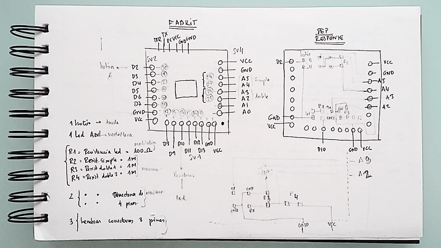
DESIGNING THE TWO SENSOR STEP RESPONSE BOARD
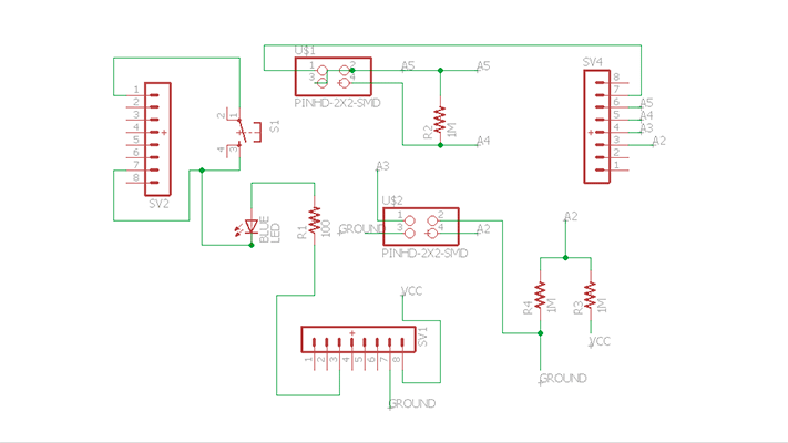
From the Fabkit files (board and schematic) I created the board that adapted to it. For designing it I imported these files to Eagle and I erased all the connectors that were on the Fabkit board and then I did the schematic file for my board following the scheme that I did. This way it was easier for me. As you can see in the image I needed four analog pins to connect both sensors: the loading one and the transmit+receive one.
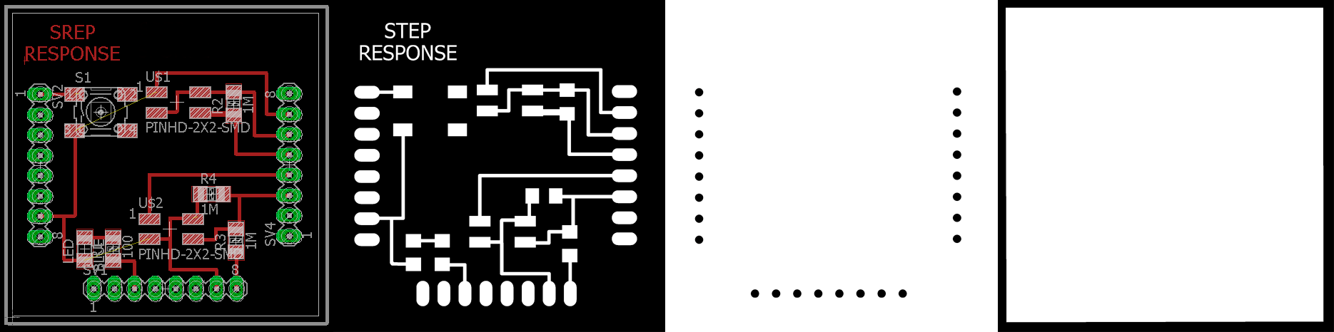
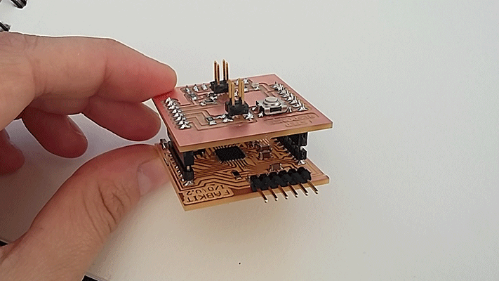
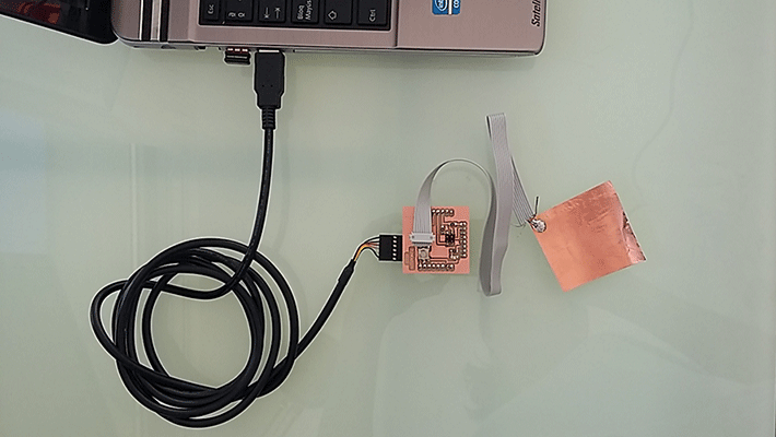
After designing my two sensor board, I exported the file to .png files in order to mill it with the modela. Now my board had the same measures as the Arduino board so both fit together to work as one board.
PROGRAMMING THE TWO SENSOR STEP RESPONSE BOARD
LOADING SENSOR
As I’ve never programmed in C I decided to program my sensor in Arduino. I found a very similar sensor in the Arduino library (capacitive sensing) but this sensor works in a different way because it uses digital pins instead of analog pins. This was not a problem because I connected my sensors to analog pins and they can work as digital.
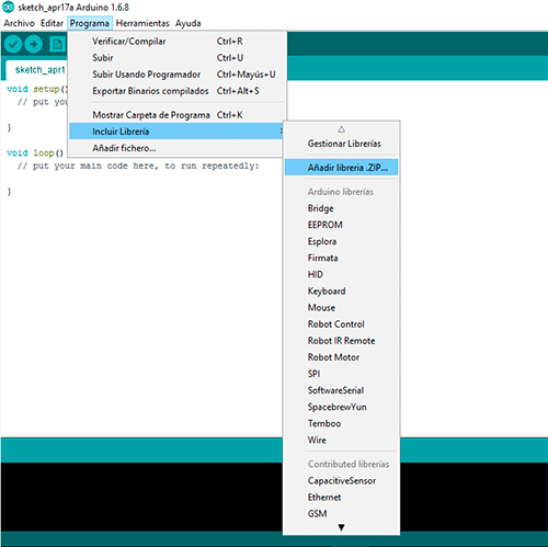
I downloaded the libraries and then I installed them in order to work with them. I modified the example sketch made by Paul Badger as he was using three sensors and I only needed one. I included a LED as an output in the sketch so when the sensor detected voltage changes the LED went on or off.
Step Response loading 1 from msantisteban on Vimeo.
Step Response loading 2 from msantisteban on Vimeo.
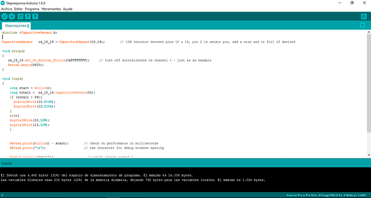
CODE
#include


CapacitiveSensor   cs_18_19 = CapacitiveSensor(18,19);        // 10M resistor between pins 18 & 19

void setup()
{
   cs_18_19.set_CS_AutocaL_Millis(0xFFFFFFFF);     // turn off calibration
   Serial.begin(9600);
}

void loop()
{
    long start = millis();
    long total1 =  cs_18_19.capacitiveSensor(30);
    if (total1 > 99){
      digitalWrite(10,HIGH); //turn Board LED on
      digitalWrite(13,HIGH); //turn Arduino Board LED on
    }
    else{
    digitalWrite(10,LOW);   //turn Board LED off
    digitalWrite(13,LOW);  //turn Board LED off
    }


    Serial.print(millis() - start);
    Serial.print("\t");

    Serial.println(total1);
    Serial.print("\t");


    delay(100);                             // arbitrary delay to limit data to serial port
}
Problems
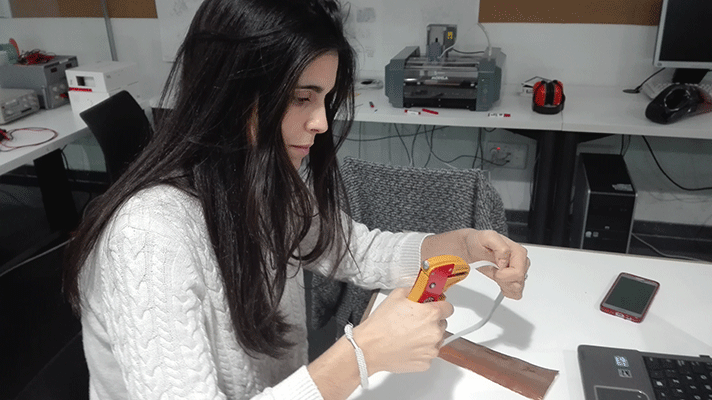
I had some trouble because when I uploaded the program there was a short-circuit in my board and my computer was turning off every time I connected my board to it. I discovered that the wire that connected my sensor to the board was soldered in a wrong way; I soldered also the ground wire to it. I desolder it and the program worked!
C PROGRAMMING
After checking that the program worked the next step was introducing Neil’s .c program to the board and checking again if the sensor worked. My instructor taught us another easier way to upload the .c program using Arduino IDE skipping the necessity of working from the terminal and with the AVRDude.
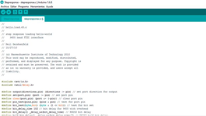
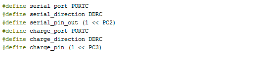
It is a very simple way in which an Arduino bootloader is needed. First of all I created a new tab in the Arduino IDE with the .c extension and then I copied the text from Neil’s .C program I modified the registers for (PORT, DDR and PIN). In my case I connected the sensor to PC2 and PC3 so in the definitions I changed “PORTB” TO “PORTC”, “DDRB” to “DDRC”, “PB2” to “PC2” and “PB3” to “PC3”. After modifying the ports pins I uploaded the program as an arduino one.
FILES:
Step Response Loading hello-world