The aim for this week’s assignment was to design a 3D mould, machine it, and cast parts. I wanted to do something for my final project but as I don’t have the pieces well defined yet I decided to do a necklace.
First of all I made some small sketches of how I wanted my piece to be. As my design was flat I decided to complicate it a bit more making the both sides of my necklace different, this way I had to do a mould made up of two different parts. I thought my necklace to have a hollow part and a filled part.
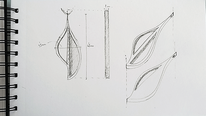
With these sketches I understood how I had to do the different parts of the mold because both sides were different and I had to design the union between them.
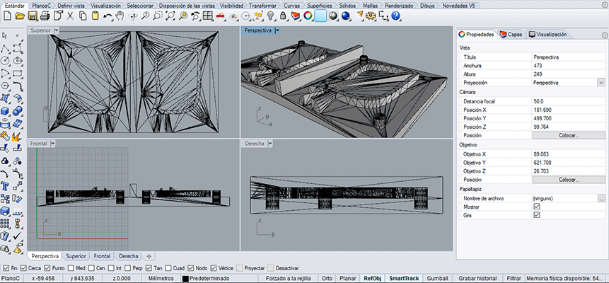
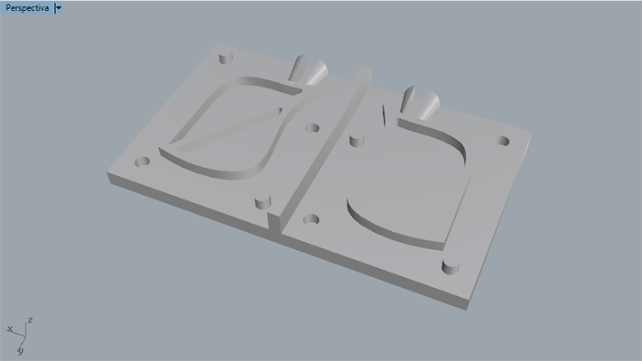
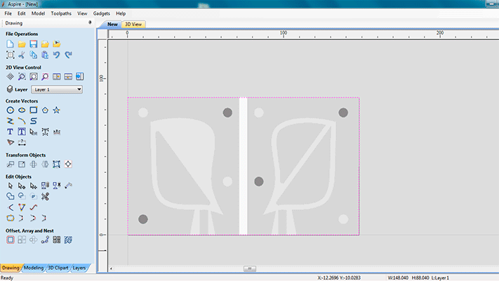
I modelled both parts of the mould (the front one and the one in the back) taking into account the air exit and the liquid (material) intake. As I was going to machine my piece with de CNC milling machine with wax, I had to take into consideration the tools that I was going to use (the 6mm and the 3mm end mill) and the measures of the wax block, in my case were: 148 length x 88 width x 37 tall.
For the machining I used the CNC milling machine and the Aspire program that allows us to make cuts in 3d. This program works very similar to the Fab Modules, it converts an .STL file into pixels so for each pixel it associates a height. We had to configure the work space measures the closest to the real size in order to have more resolution. At the end we will have a black and white image where the black colour is height =0 and the white colour is the tallest height.
For machining the countermould I had to hold the block of wax in order to make sure that it won’t move. For this, I milled a hole in a MDF 16mm board and then I fitted the block of wax in it. Doing it this way allowed me to have the same reference point (the upper corner) and to make the most of the block size in order to don’t lose material.
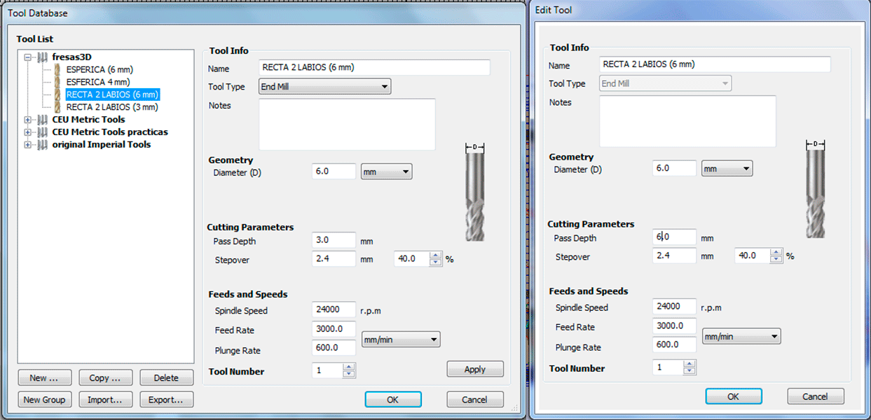
Selecting the mills
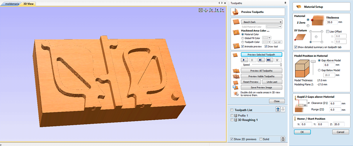
Toolpaths: I did three different types of toolpaths, one for the MDF board, another for the 3D roughing and the third one for the final finish.
1) In order to do the toopath for the hole of the MDF 16mm board I did the form of the wax block with its measures and then I saved the toolpath.
2) When doing the 3D Roughing toolpath, I also selected the edge of my block. I selected the tool, in this case a 6mm end mill. I modified the properties for each path because you can choose the grade of roughness that you want.
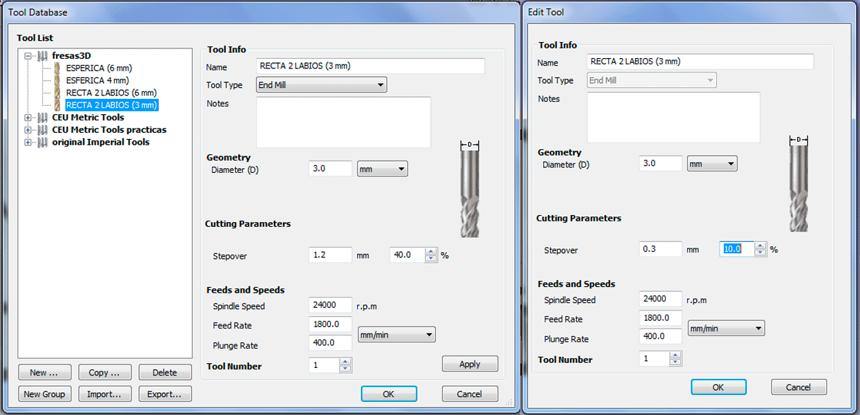
3) The last toolpath was the finish one. For this one as I wanted a better finish I selected the 3mm end mill.
Rough toolpath: 6mm end mill.
Finish toolpath: 3mm end mill.
Extra work: Fab Modules
For the assignment I used the TEC-CAM 1003 CNC using aspire program because it was but I could have used the Rolland mill MDX-20 using the Fab Modules following these steps:
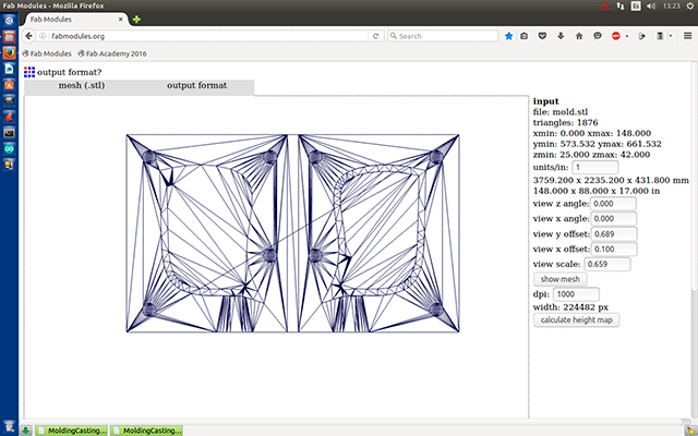
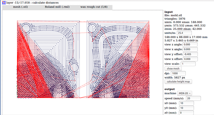
Open fabmodules.org and import the file form our computer, in my case I had the .stl file so I selected (.stl mesh) in the input format. Then it gives you the option to select the output format: I selected Rolland mill (.rml).
As the other procedure you have to do two different paths (process) the wax rough cut (1/8) and the wax finish cut (1/8) but first of all you have to calculate the height map selecting the correct units in my case (25.4)
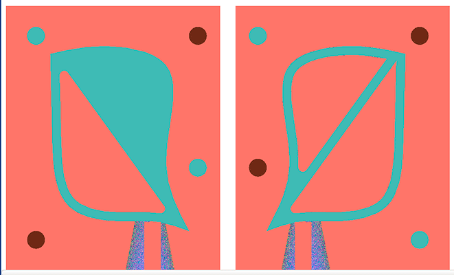
This is the image for the height map:
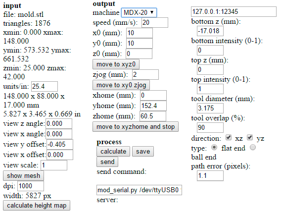
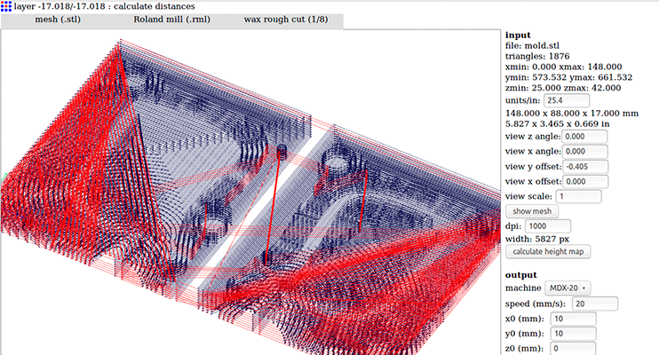
Then you have to introduce all the parameters, select the machine and the process. I selected the diameter of the mill of 3.175 with a top intensity of 1mm and an overlap 90% because I wanted to be very accurate.
The program starts calculating the paths:
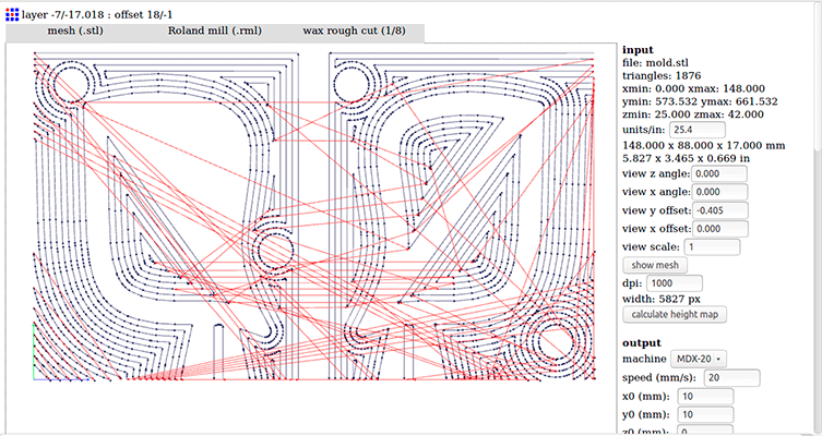
As you can see in the image the rough path is very accurate and needs a lot of paths because it only has 1mm difference between the heights of the paths.
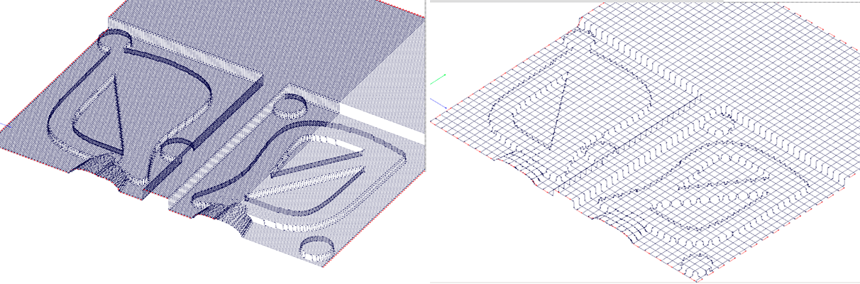
For the assignment I used a 6mm end mill for the rough path and a 3mm end mill for the finish path. In the following picture you can appreciate the difference between each tool. It can be more accurate or less depending on the overlap and the depth of each toolpath
Problems
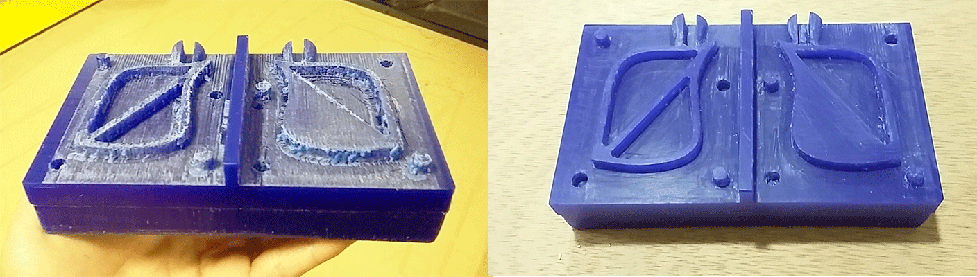
While milling the countermould the mill didn’t evacuate properly the wax so the excess of wax stayed in the head of me mill. This caused a big ball of wax that crashed with my piece as it was milling it. At the end, my mould had some holes and it also had excess of wax stucked to it that I had to remove it later with sandpaper.
As I wanted to take advantage of the entire wax surface I didn´t design the walls for doing the mould because this would reduce the wax surface so I had to put 4 walls in order the silicone don’t be spilled.
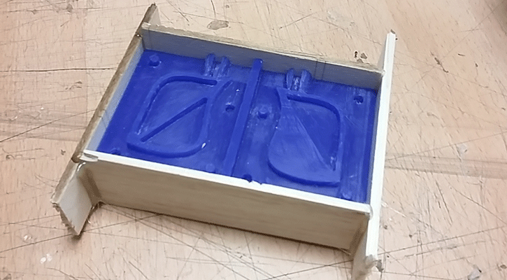
Doing the silicone Mould
I wanted to replicate my 3d model in resin and wax and for doing it the best option was doing the mould in silicone because this way the mould could be bend. For it, I mixed the base and the catalyst with a proportion 100% base 5% catalyst. After mixing the components I pour it into the countermould and wait 24h because it’s the curing time.
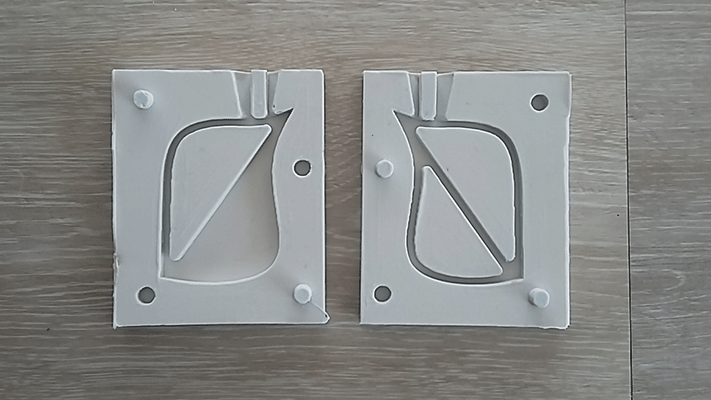
After 24h I removed the silicone and my mould was ready to do the cast.
Doing the casting
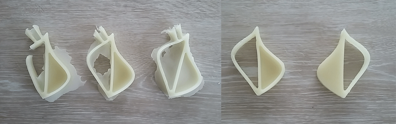
First of all I did the casting with wax. I had to reinforce my mould with tape to ensure that it wasn’t opening. At the beginning I had some problems because I poured the hot wax very quickly and there were some bubbles in the result. The next time I did it slowly and inclining a bit the piece the 3d model was perfect!
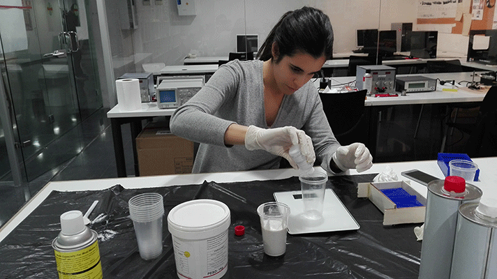
Next step was doing it with resin (Polyurethane resin). The resin is comprised of two components that have to be mixed with a proportion of 50% component A (polyether polyol) and 50% component B (isocyanate). These components are very injurious so I had to protect myself with a mask, gloves and a face protection.
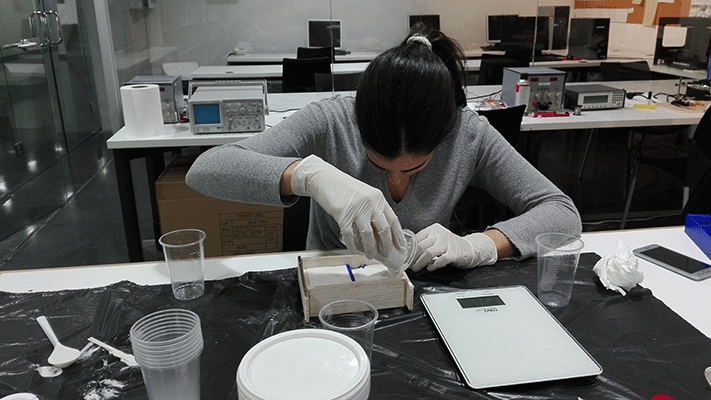
After mixing both components I had to be very fast to pour down the mixture into the mould. I did the same thing as with the wax, I reinforced the mould with tape. The final result wasn’t as good as with the wax.
FILES: