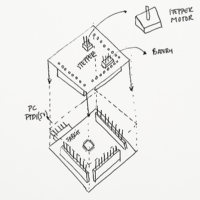
This week’s assignment was adding an output device to a microcontroller board and programmed it to do something. As my final project was about moving some type of hoist motors I thought that the motor that fitted best with my final project was the bipolar stepper motor because this way I can control better the motor movements. As I did for week 10 assignment I designed my motor board as a shield of my Fabkit Arduino board that I did on the embedded programming assignment because this way, I could use my Fabkit for other purposes.
DESIGNING THE BOARD
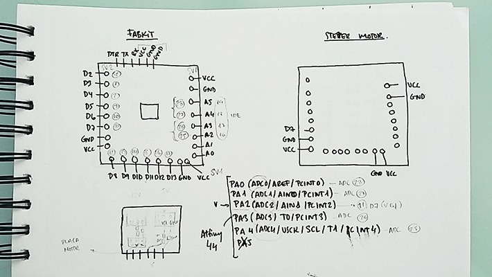
First of all what I did was the same thing I did for inputs devices assignment: with the help of the microcontroller datasheet, in my case the ATMega168 I did a very simple scheme showing all the pins and its functions of the processer in order to know where do I had to connect my motor. All the pins were connected to one pin of the three 8 pin headers so I had to see which one was the correct one.
When designing the board I took into account how I was going to programme my motor because it varies the pins connected to depending on the way it is programmed. As I am not very skilled on programming I decided to continue programming with Arduino. I saw that the libraries that Arduino uses in their sketch examples are used with digital pins. I saw other examples that were connected to analog pins so as the analog pins works as digital pins I decided to connect my motor to analog ones just in case.
ANALOG PINS: (Motors)
As I wasn’t very sure if I had to connect my motor to digital or analog pins I decided to connect them to analog pins. There are only 4 analog pins that I could use in my Fabkit and I needed 4: I looked in the datasheet which pins were the analog ones in order to connect my motor to them. As I needed 4 analog pins for the two sensors I didn’t have trouble with that because the microcontroller had 4 analog pins.
Number pin 25: PC2 (ADC2/PCINT10) connected to A2.
Number pin 26: PC3 (ADC3/PCINT11) connected to A3.
Number pin 27: PC4 (ADC4/SDA/PCINT12) connected to A4.
Number pin 28: PC5 (ADC5/SC1/PCINT13) connected to A5.
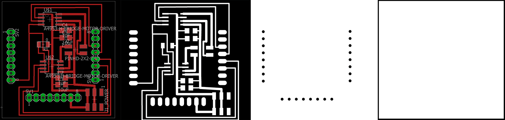
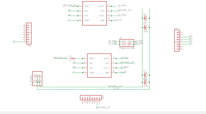
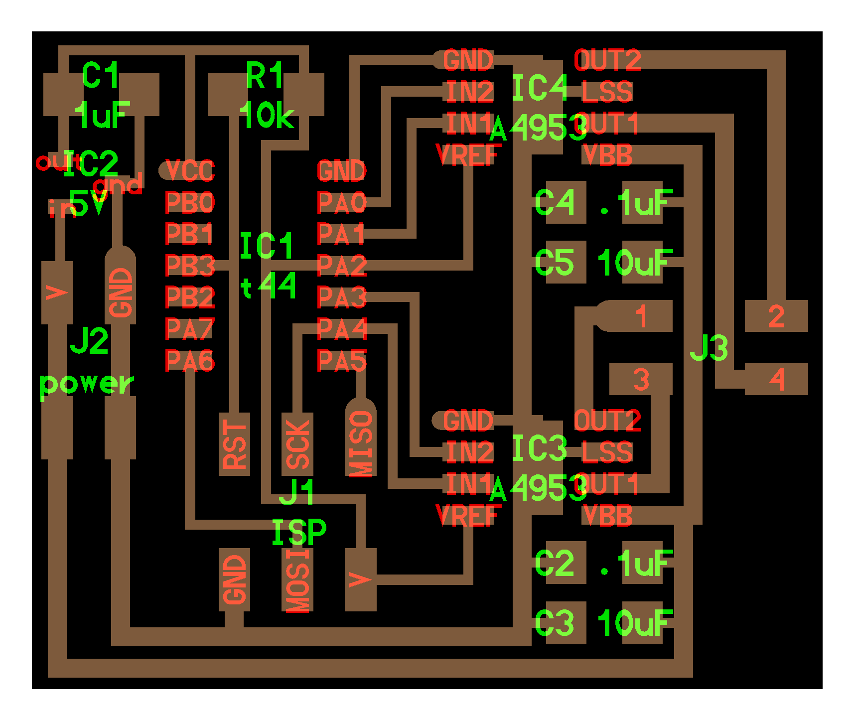
When doing the scheme for my motor board I used Neil’s board example but as I was going to do a shield for my Fabkit I had to identify which elements I had to clear because my Fabkit has already a microcontroller on it. I reached the conclusion that I had to clear the 6 pin header for programming it, the microcontroller, the regulator, the 1uF capacitor and the 10k resistor.
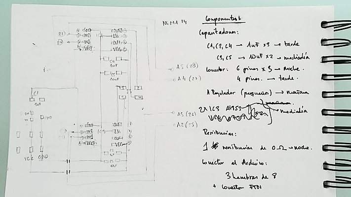
Once I did the scheme I drew the final board in eagle using the (.sch) and (.brd) files of my Fabkit in order to had the same measures and do the shield.
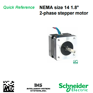
STEPPER MOTOR
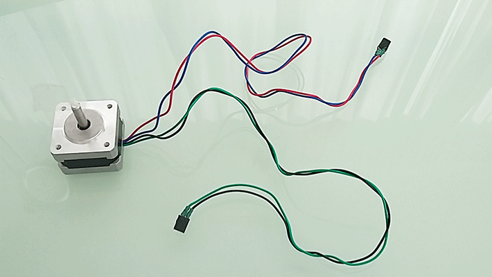
I chose a bipolar stepper that has two separate windings and 4 wires. As my stepper motor hadn’t got the “coil end” wires isolated in pairs I had to identify them with the aid of a multimeter although it is specified in the datasheet black wire connected to the green wire and the blue wire connected to the red wire. I needed to used 4 pins to control my bipolar stepper.
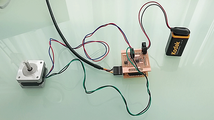
H-bridge
The H-bridge is a circuit that allows voltage to be applied across a load (like a motor) in either direction.
Batery
As my stepper motor can draw more current than the Fabkit 5V can support, I needed to have a separate power source in my case a 9V battery. I know that my stepper motor is 12V but a 9V battery should be enough to check if it works. It was very important to connect both grounds together.
PROGRAMMING THE BOARD
As I said before, the Arduino IDE comes with a stepper library that I used to test my circuit: File/Examples/Stepper.
For programming it I had to guess the number of steps per revolution of my motor with the datasheet. I knew that my motor moves 1.8º per step and a revolution is 360º so in one revolution my motor does 200 steps.
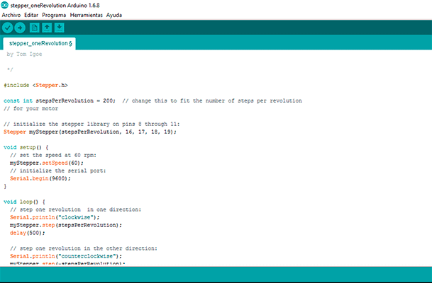
MOTOR SKETCH
 #include <Stepper.h>

const int stepsPerRevolution = 200;  // change this to fit the number of steps per revolution
// for your motor

// initialize the stepper library on pins 8 through 11:
Stepper myStepper(stepsPerRevolution, 16, 17, 18, 19);

void setup() {
  // set the speed at 60 rpm:
  myStepper.setSpeed(60);
  // initialize the serial port:
  Serial.begin(9600);
}

void loop() {
  // step one revolution  in one direction:
  Serial.println("clockwise");
  myStepper.step(stepsPerRevolution);
  delay(500);

  // step one revolution in the other direction:
  Serial.println("counterclockwise");
  myStepper.step(-stepsPerRevolution);
  delay(500);
}
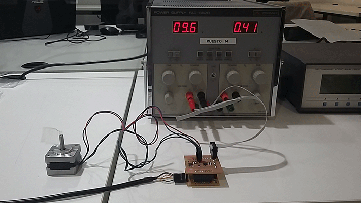
Problems
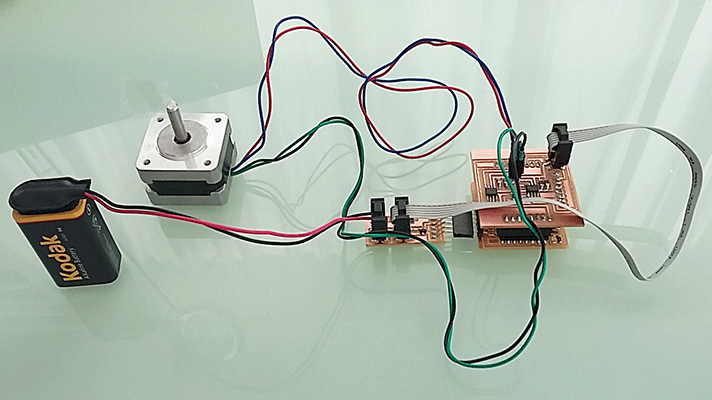
My stepper motor was not working so I had to check the wiring because the program is well done. After checking with the multimeter I founded that the problem was that the connections weren't well done and the 9V baterry wasn't enough for the motor. I put more tin on it and I connected it to 12V and it worked!
Stepper motor 1 from msantisteban on Vimeo.
EXTRA WORK
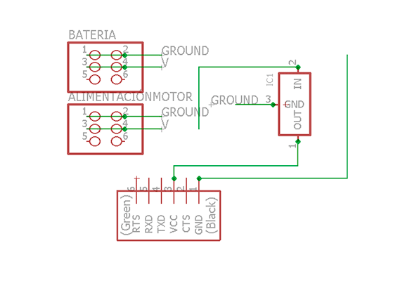
REGULATOR
I decided to do a regulator board aswell because I wanted my final project to have only one power supply instead of using one power supply for the boards and another for the motors. This regulator board would receive 12V. I designed two ways out: 12v are connected to the regulator board and to the motors and then the regulator converts the 12V into 5V that goes to all the other boards.
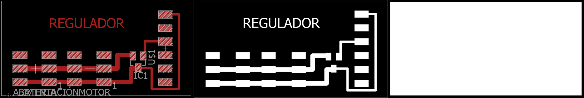
Problems
When I did the regulator board I didn’t realize the position of GROUND and VCC in the motor board so I did it the other way round, that is to say that in my motor board ground was on the left side and vcc in the center and in the regulator board ground was in the center and vcc in the left side so I had to redo the regulator board.
FILES: