ELECTRONICS
First of all, when designing a Project it was necessary to make a plan and dividing the work in different tasks in order to organize the time available for the project. The final project is divided in three different parts: the structure, the connection pieces, and the electronics. Once differentiated the different tasks of the project I started designing the structure:
Designing the structure
The first thing I did was thinking about how my project's structure should be and then I did some sketches of how it would work better. The principal concern was creating a hoist system and how I was going to support it so I thought about doing a very simple acrylic arch.
Taking into account that the hoist system would consist of three stepper motors attached to a string I considered that the best option for allowing the vertical movement was transmitting it through a system of pulleys. These pulleys would be place on the upper part of the arch.
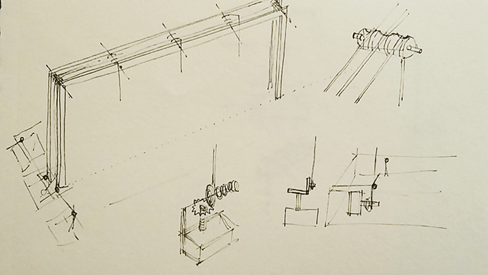
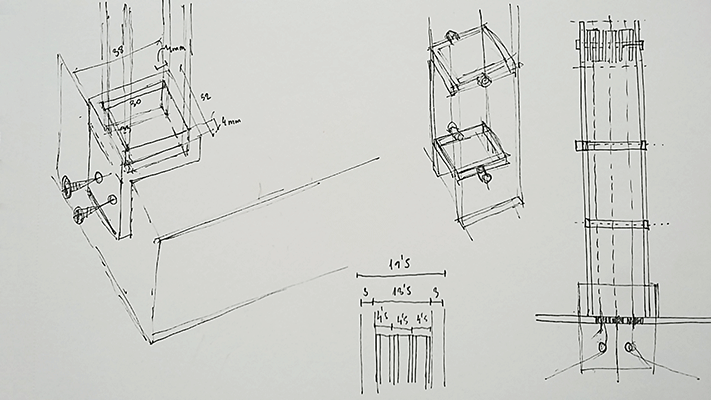
I designed each element of the system: the pulleys and how they were going to be placed in the structure. I thought about separating the hook and the pulley to allow its rotatory movement. It is a very a very simple way in which an elongated piece goes through the pulley and prevents it from falling down due to the geometry of this piece.
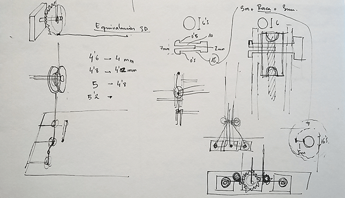
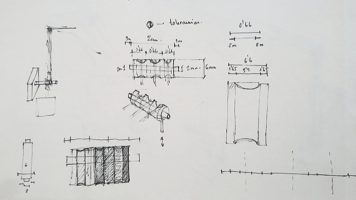
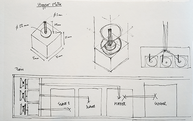
I also was very concern about how I was going to be able to transmit the movement from the motors to the string. It had to be a piece that could keep a certain size of the string and that moves at the same time as the motor. I did some sketches with very complicated solutions and at the end I thought they weren’t the best option so I decided to base this piece in the sewing machines and its bobbin. I designed a pieces that would work as the bobbin that fit together exactly with the motor.
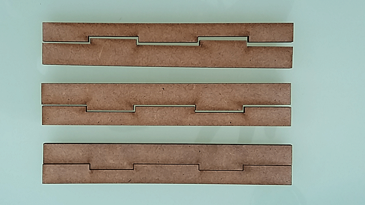
I also designed the pieces that give toughness to the structure and that allows the different strings coming from the motors pass through them.
This sketch represents what I had in mind for my final project. We can see all the different parts and elements such as the electronics, the structure, the connection pieces,
the pulley system..etc
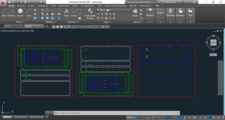
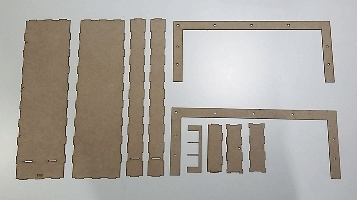
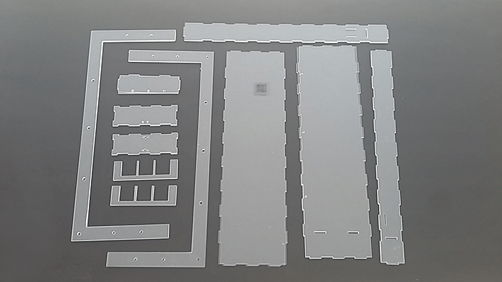
2D Design
Once I knew how I wanted my final project to be, the next step was to designing it in the computer with its real measures and start doing the cut plans. Before cutting the final structure in acrylic I wanted to do a prototype in MDF in order to see if everything that I designed worked well. For the 2d design I used Autocad.
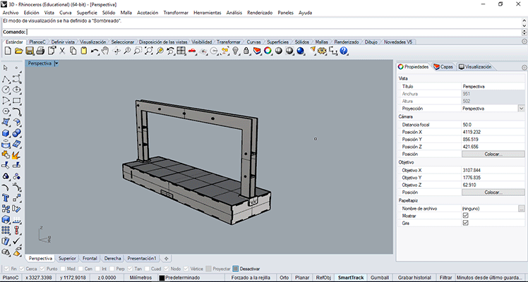
3D Design
For the 3d design I used Rhinoceros because it’s the best modelling program. You can observe in the 3d model the different parts that it has.
3D printing Test
When I had all the pieces modelled I printed some tests just to see the tolerances between the pieces in order to know which measures fitted better with the motor, the holes and which kind of bobbin worked better the flat one or the one with an angle.
printing the pieces from msantisteban on Vimeo.
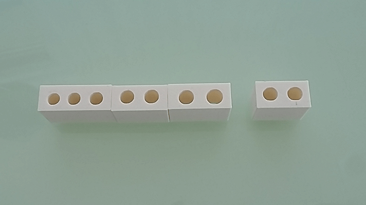
These are the tests pieces that I modelled to see which one fits better with the motor.
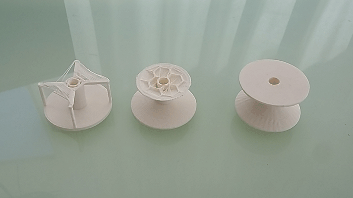
These are the different test for the string bobbin that I modelled. I decided to test the one in the right that has an angle just to prove that it works because I wasn’t very sure if it was going to work well.
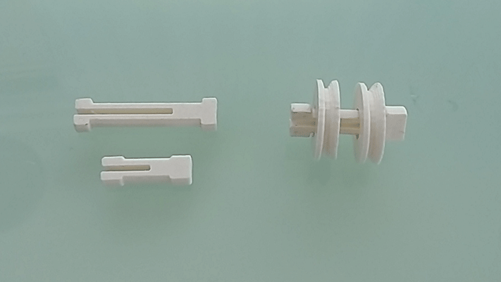
These pieces are the ones that will be used for hooking up the pulleys to the structure.
Lasercut test
I also cut some tests with different tolerances in order to know the ones for the MDF and having the exact joints for the prototype. I had to draw the plans for cutting it 0,1mm bigger.
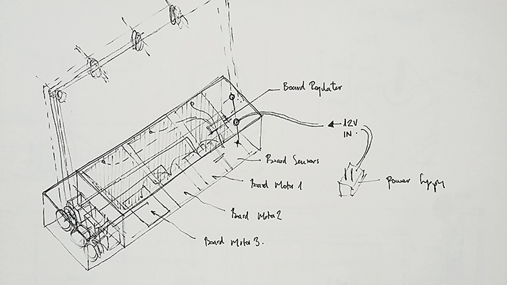
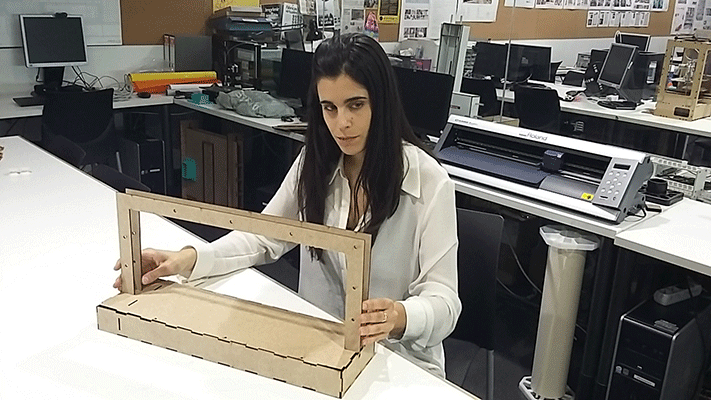
Once all the tests were done the next thing I did was assemble the mdf prototype with all printed pieces to see if the structure that I invented worked well but first of this I had to select the right string and use a power supply.
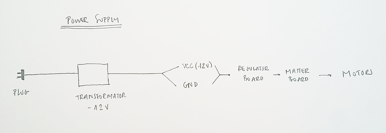
Power Supply
I needed to use a different power supply than the computer one because the motors use 12V. I also had the regulator board that I fabricated on the Output devices assignment so I used this regulator for my final project. The idea was to connect 12V to the regulator board and to the motor boards. Then the regulator board reduces from 12V to 5V because the microcontrollers work at 5V and these 5V goes to each board through the I2C connection. For the power supply I used one that was in my Fab Lab. It was a 12V and 1A. I cut the wire and identify which one was GND and wich one was VCC to connect them to the regulator board.
Selecting the String
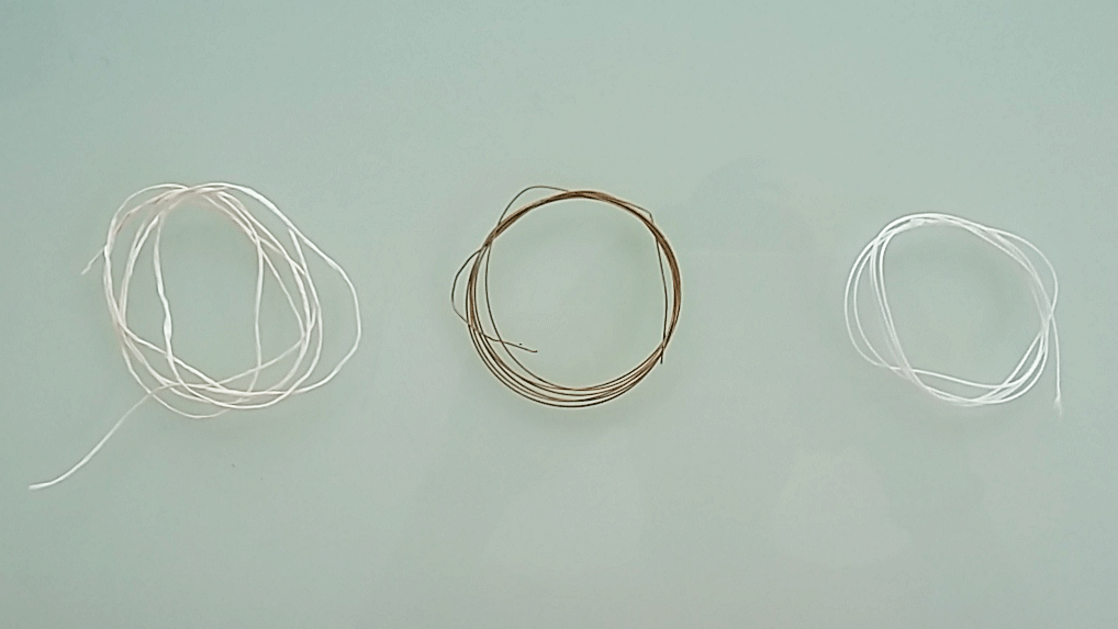
Selecting the correct string was very important because not all strings are the same and work well. As I had the mdf prototype I could test which one worked better. I started testing a generic string but it turned out not to slip well so I thought about using a metallic one. Using this type of string was not a good idea because it was very delicate and it could be deformed very easily so it could prevent a smooth movement. I found another type of string that is used for bookbinding. This string is strong enough to support things hanging from it and its movement is very smooth when the string is stretch. . In the following picture at the left is the generic string I used first, in the middle the metallic one and in the right the one I finally used, the one that worked better.
Here there is a video that shows how the prototype worked. For it, I used the Arduino sketches that I used in the Output devices assignments. I needed a very simple sketch to check if the prototype was working.
motor test 1 from msantisteban on Vimeo.
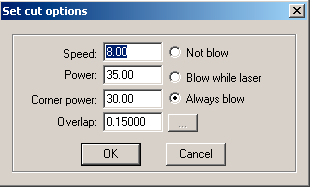
As the MDF prototype was working I decided to do the final model: the one in acrylic. I also did some lasercut tests in order to see the tolerances, but this time I used different parameters. As I had to cut acrylic I used a low power and a slow speed because I didn’t want the laser to be reflected on the metal bars that are used hold the acrylic sheet.
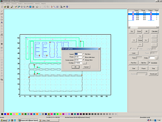
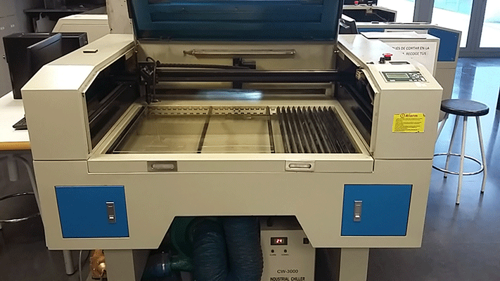
In the video we can see how the sheets were cut with the lasercut.
lasercut1 from msantisteban on Vimeo.
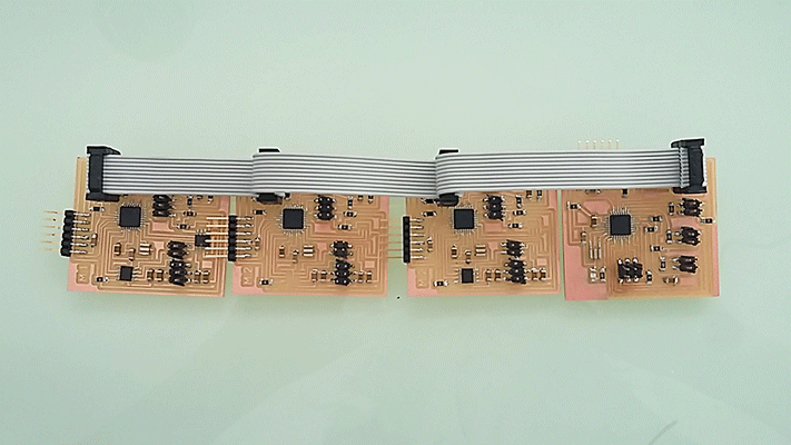
The different pieces
All the electronics are based on Networking and Communications between boards though I2C. I considered having 4 different boards connected between them. These boards were designed and programmed in the Networking and Communication assignment. In this assignment I designed the motor boards and checked if they worked well moving the motors, I also designed the sensor board with three different sensors and I could check that they worked also well. I studied how the I2C connection worked in order to do the final sketch
This is a scheme of how the electronics works.
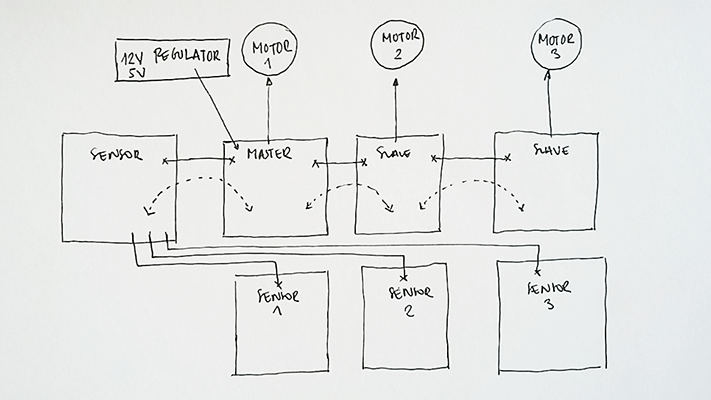
The sensors board: is receiving data from three different sensors. This board will be acting as the Master board because this way it can send the data through I2C to the slave boards.
The motor boards (X3): these boards are receiving data from the master board. These boards give orders to the motors. When to move and when to stop.
So far I had been testing the sensors with LEDs boards as the output in the Networking and communications assignment but I wanted to put together the sensors and the motors so I started to do another Arduino sketch: I used the same Master sketch but I updated the Slave one, instead of turning on and off the LED board I added the motor movement:
Master Sketch
//Mastertressensores:


#include <CapacitiveSensor.h>
#include <Wire.h>
CapacitiveSensor   cs_5_17 = CapacitiveSensor(5,17);
CapacitiveSensor   cs_6_16 = CapacitiveSensor(6,16);
CapacitiveSensor   cs_9_15 = CapacitiveSensor(9,15);
void setup() {
cs_5_17.set_CS_AutocaL_Millis(0xFFFFFFFF);     // turn off autocalibrate on channel 1 - just as an example
cs_6_16.set_CS_AutocaL_Millis(0xFFFFFFFF);     // turn off autocalibrate on channel 1 - just as an example
cs_9_15.set_CS_AutocaL_Millis(0xFFFFFFFF);     // turn off autocalibrate on channel 1 - just as an example

Serial.begin(9600);
Wire.begin(); // join i2c bus (address optional for master)
pinMode(13, OUTPUT);

}
byte x = 0;

void loop() {
  // read the sensor:
  long total1 =  cs_5_17.capacitiveSensor(30);
  long total2 =  cs_6_16.capacitiveSensor(30);
  long total3 =  cs_9_15.capacitiveSensor(30);

      if (total1 > 99){
        x = 1;
        digitalWrite(13,HIGH);
        Wire.beginTransmission(1); // transmit to device #1
        Wire.write(x);              // sends one byte
        Wire.endTransmission();    // stop transmitting
        Serial.println(x);
       }
     else{
       digitalWrite(13,LOW);
        x = 0;
        Wire.beginTransmission(1); // transmit to device #1
        Wire.write(x);              // sends one byte
        Wire.endTransmission();    // stop transmitting
        Serial.println(x);
       }


       if (total2 > 99){
        x = 1;
        digitalWrite(13,HIGH);
        Wire.beginTransmission(2); // transmit to device #2
        Wire.write(x);              // sends one byte
        Wire.endTransmission();    // stop transmitting
        Serial.println(x);
       }
     else{
       digitalWrite(13,LOW);
        x = 0;
        Wire.beginTransmission(2); // transmit to device #2
        Wire.write(x);              // sends one byte
        Wire.endTransmission();    // stop transmitting
        Serial.println(x);
       }

       if (total3 > 99){
        x = 1;
        digitalWrite(13,HIGH);
        Wire.beginTransmission(3); // transmit to device #3
        Wire.write(x);              // sends one byte
        Wire.endTransmission();    // stop transmitting
        Serial.println(total3);
       }
     else{
       digitalWrite(13,LOW);
        x = 0;
        Wire.beginTransmission(3); // transmit to device #3
        Wire.write(x);              // sends one byte
        Wire.endTransmission();    // stop transmitting
        Serial.println(total3);
       }

}
Slave Sketch
// Slavemotor


#include <Stepper.h>
#include <Wire.h>
const int stepsPerRevolution = 200; //steps in a revolution
volatile int y = 0;
Stepper myStepper(stepsPerRevolution, 3, 4, 5, 6); //motor pins

void setup() {
  Wire.begin(3);                // join i2c bus with address #1
  Wire.onReceive(receiveEvent); // register event
  myStepper.setSpeed(60); // set the speed at 60 rpm:
  pinMode(13,OUTPUT);
}

void loop() {


if (y==1){
myStepper.step(stepsPerRevolution); // step one revolution  in one direction:
myStepper.step(-stepsPerRevolution); // step one revolution  in one direction:
y=0;
}


}

// function that executes whenever data is received from master
// this function is registered as an event, see setup()
void receiveEvent(int hola){
volatile int x = Wire.read();    // receive byte fom wire

if (x==1){
digitalWrite(13,HIGH);
y=1;

}
else{
digitalWrite(13,LOW);
}
}
I wanted to introduce the boards I made in the Networking and Communication assignment in the basement of the structure but I had to do another wire: the one that connected 12V to the boards. When I did the wire I uploaded the programs made in the assignment but it only worked one motor. It took me a lot of time to know where the problem was and after checking all the connections, connecting the boards to two different power supplies I reached the conclusion that there was a problem with the new wire I did and in effect, there was a connector that was badly connected.
In the following vodeo we can observe how the different sketches worked with the sensors.
sensors and motors from msantisteban on Vimeo.
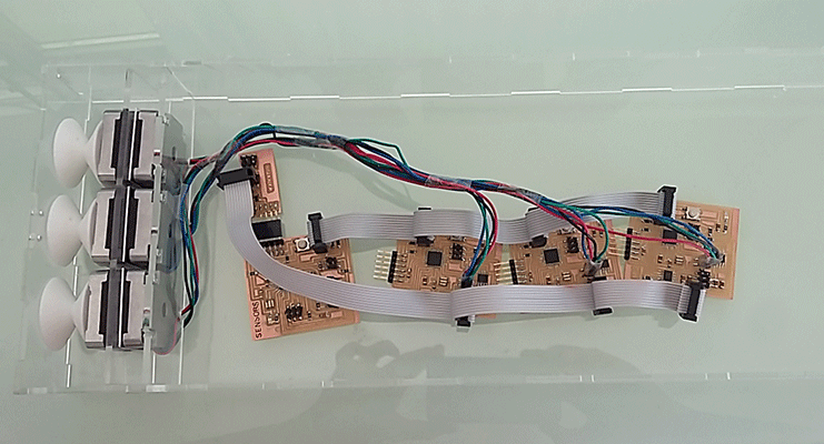
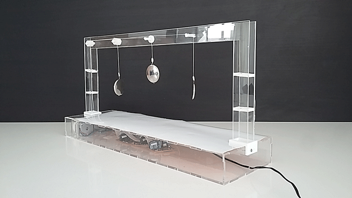
I put all together the structure and the electronics and this was a test of how it worked all together.
test1 from msantisteban on Vimeo.
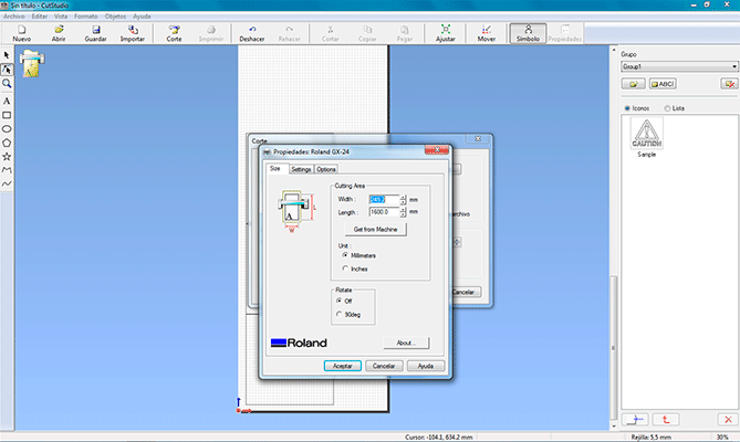
I didn’t have the final sensors so I decided to cut them with the vinyl cutter using copper vynil. I had to do some tests in order to see which parameters were the best for this material and at the end I reached the conclusion that its parameters were: 3cm/s speed and 120gf of strength. These parameters are different that the ones used for the normal vinyl, I slower the speed and put more strength for the copper.
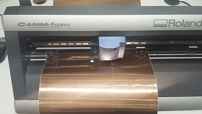
cutting the sensors from msantisteban on Vimeo.
Them I soldered the wires to the sensors and connected them to the sensor board. I put the sensors in its place.
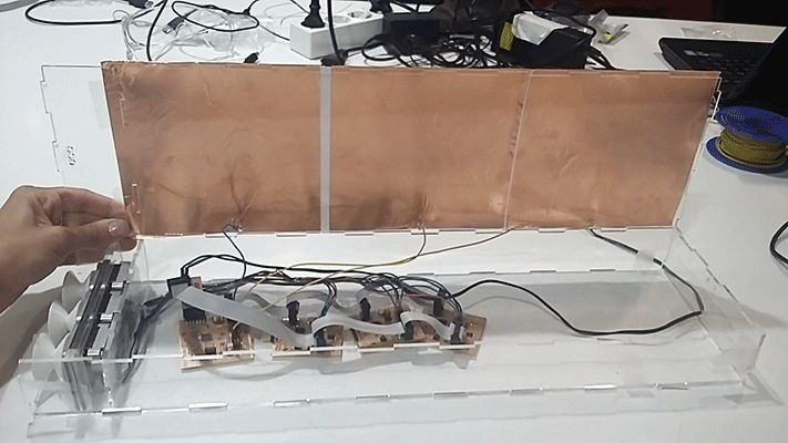
In the following video you can apreciate that the final sensors worked well with the last Arduino sketches.
sensors test from msantisteban on Vimeo.
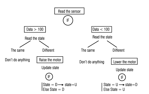
After doing the final sensors I had to do the final sketch for my final project because the one I had wasn’t the final program I wanted to use. I did a scheme of how I wanted the program to be and what I added was giving a state to the motor: when the motor is down its state is “D” and when the motor is up its state is “U” and every time there is a change in the values of the sensor this state changes. This is the program scheme:
Master Sketch
//mastertressensoresidayvuelta2


#include <CapacitiveSensor.h>
#include <Wire.h>
CapacitiveSensor   cs_5_17 = CapacitiveSensor(5,17); // declare capacitive sensor 1
CapacitiveSensor   cs_6_16 = CapacitiveSensor(6,16); //declare capacitive sensor 2
CapacitiveSensor   cs_9_15 = CapacitiveSensor(9,15); //declare capacitive sensor 3


void setup() {
cs_5_17.set_CS_AutocaL_Millis(0xFFFFFFFF);     // turn off autocalibrate on channel 1 - just as an example
cs_6_16.set_CS_AutocaL_Millis(0xFFFFFFFF);     // turn off autocalibrate on channel 1 - just as an example
cs_9_15.set_CS_AutocaL_Millis(0xFFFFFFFF);     // turn off autocalibrate on channel 1 - just as an example

Serial.begin(9600);
Wire.begin(); // join i2c bus (address optional for master)
pinMode(13, OUTPUT); //set led pin as an output

}
byte x = 0;

void loop() {
  // read the sensor:

  char state1 = 'D'; // sensor1 first state DOWN
  char state1_2 = 'U'; // sensor1 second state UP

  char state2 = 'D'; // sensor2 first state DOWN
  char state2_2 = 'U'; //sensor2 second state UP

  char state3 = 'D'; // sensor3 first state DOWN
  char state3_2 = 'U'; //sensor3 second state UP

  long total1 =  cs_5_17.capacitiveSensor(30); //sensor1 value
  long total2 =  cs_6_16.capacitiveSensor(30); //sensor2 value
  long total3 =  cs_9_15.capacitiveSensor(30); //sensor3 value

      if (total1 > 99){
        if  (state1 != state1_2){  // if (sensor1 first state) different than (sensor1 second state) send byte x = 1 to motor 1
                                   // in order to move it.
             x = 1;
             digitalWrite(13,HIGH);
             Wire.beginTransmission(1); // transmit to device #1
             Wire.write(x);              // sends one byte
             Wire.endTransmission();    // stop transmitting
              if (state1 == 'D'){ // if sensor1 is DOWN change state to UP
                state1 = 'U';
                }
              else {
                state1 = 'D';
                }

         }
      }
     else{ // Don't move motor
       digitalWrite(13,LOW);
        x = 0;
        Wire.beginTransmission(1); // transmit to device #1
        Wire.write(x);              // sends one byte
        Wire.endTransmission();    // stop transmitting

       }
        Serial.print(state1);

       if (total2 > 99){
           if  (state2 != state2_2){   // if (sensor2 first state) different than (sensor2 second state) send byte x = 1 to motor 1
                                       // in order to move it.
             x = 1;
             digitalWrite(13,HIGH);
             Wire.beginTransmission(2); // transmit to device #2
             Wire.write(x);              // sends one byte
             Wire.endTransmission();    // stop transmitting
              if (state2 == 'D'){     // if sensor2 is DOWN change state to UP
                state2 = 'U';
                }
              else {
                state2 = 'D';
                }

         }
      }
     else{
       digitalWrite(13,LOW);  // Don't move motor
        x = 0;
        Wire.beginTransmission(2); // transmit to device #2
        Wire.write(x);              // sends one byte
        Wire.endTransmission();    // stop transmitting

       }

       Serial.print(state2);

       if (total3 > 99){
            if  (state3 != state3_2){  // if (sensor3 first state) different than (sensor3 second state) send byte x = 1 to motor 1
                                       // in order to move it.
             x = 1;
             digitalWrite(13,HIGH);
             Wire.beginTransmission(3); // transmit to device #3
             Wire.write(x);              // sends one byte
             Wire.endTransmission();    // stop transmitting
              if (state3 == 'D'){ // if sensor3 is DOWN change state to UP
                state3 = 'U';
                }
              else {
                state3 = 'D';
                }

         }
      }
     else{  // Don't move motor
       digitalWrite(13,LOW);
        x = 0;
        Wire.beginTransmission(3); // transmit to device #3
        Wire.write(x);              // sends one byte
        Wire.endTransmission();    // stop transmitting

       }

   }
Slave Sketch
// Slavemotorida


#include <Stepper.h>
#include <Wire.h>
const int stepsPerRevolution = 200; //steps in a revolution
volatile int y = 0;
Stepper myStepper(stepsPerRevolution, 3, 4, 5, 6); //motor pins

void setup() {
  Wire.begin(1);                // join i2c bus with address #1
  Wire.onReceive(receiveEvent); // register event
  myStepper.setSpeed(60); // set the speed at 60 rpm:
  pinMode(13,OUTPUT);
}

void loop() {


if (y==1){     //  if y=1 step one revolution  in one direction:
myStepper.step(stepsPerRevolution);
y=0;
}

}

}
In the following video you can appreciate how the sketch is printing in the serial port the motor states (the three of them) U = Up D = Down.
serial port motors states from msantisteban on Vimeo.
FILES: