
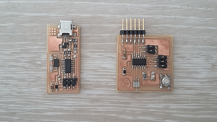
This week assignment was about programming the board that we designed on Electronics Design the “hello board+BUTTON+LED with a chosen language. For this, it was necessary to use the board designed on the assignment of electronics production FabIsp board. I also decided to create a new one, the FabKit board because I thought it would be useful for future assignments.
For the assignment was also necessary to read the microcontroller datasheet, ( AtTiny44 ) that was the one used for the hello world board and see how it works and which are its different pins... Etc.
As it was my first time programming a board everything from the datasheet was new for me and there are lots of things that I still don’t understand because you need more knowledge in electronics and in programming but I understood the basic things for the assignment.
First of all I had to understand how a microcontroller works in order to understand the datasheet. The AtTiny44 microcontroller works with an 8 bit memory. There are different types of memory or registers that can be faster and smaller, it has SRAM (faster memory), DRAM (it’s a volatile memory that when you turn it off the data disappear) EEPROM (it’s similar to the hard disk, a slower memory but bigger) FLASH (it’s like an SD memory its external) and FUSE that configures how the microcontroller is going to work.
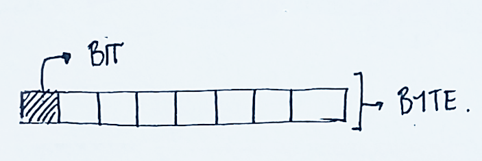
Our processor only understands the two digital values that means everything must be translated into zeros and ones (0,1) current HIGH or current LOW. These values are saved in the memory.
All the memory is divided into “blocks” that are called byte, each of these bytes are divided into 8 boxes called bits. Our processor is an 8 bit processor that means that there are 28 = 256 possible combinations of these two values (high and low)
DATASHEET
It is important to read the datasheet before programming the board because the datasheet tells you everything about the microcontroller: the things that the processer understands and can do and the ones that cannot do. Knowing all these things we can send him actions of what we want him to do.
PIN CONFIGURATIONS
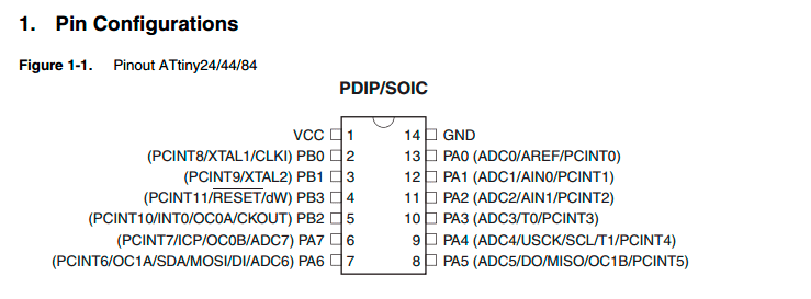
VCC: voltage in
RESET: This pin makes the program to start again
INT: interruption
MOSI: (Master Output Slave Input): Master data output and data input to the Slave
MISO: (Master Input Slave Output): Slave Data Output and input to Master
SCLK: it’s the pulse that establishes the synchronization. With each of this pulse of the clock, it reads or sends a bit.
ADC: Analog to Digital convertor for entrance pins.
OC: it’s the same as PWM (Analog simulation for exit pins)
PORTA: Port A is a 8-bit bi-directional I/O port with internal pull-up resistors. The pullup resistors are resistors inside the microcontroller that you can activate.
hello board+BUTTON+LED
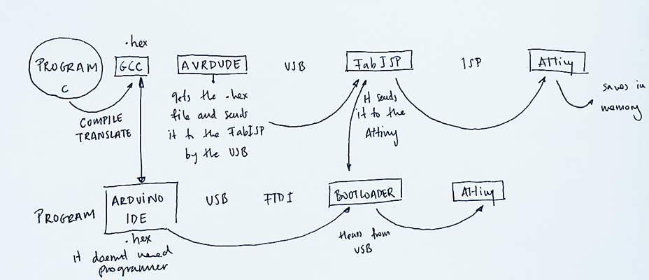
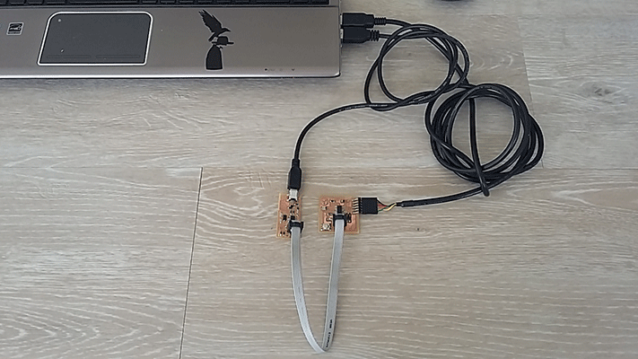
For programing the board it was necessary to connect our board to the programmer made in electronics production: the FabIsp board. I decided to program it on C so I followed the tutorials and I uploaded Neils programs: the hello.ftdi.44.echo.c and the hello.ftdi.44.echo.c.make
This is how we program a board.
CODE
Device: attiny44
Program: 706 bytes (17.2% Full)
(.text + .data + .bootloader)
Data: 64 bytes (25.0% Full)
(.data + .bss + .noinit)
C:\Users\Maria Santisteban\week8>make program-usbtiny-fuses
avr-objcopy -O ihex hello.ftdi.44.echo.out hello.ftdi.44.echo.c.hex;\
avr-size --mcu=attiny44 --format=avr hello.ftdi.44.echo.out
AVR Memory Usage
----------------
Device: attiny44
Program: 706 bytes (17.2% Full)
(.text + .data + .bootloader)
Data: 64 bytes (25.0% Full)
(.data + .bss + .noinit)
avrdude -p t44 -P usb -c usbtiny -U lfuse:w:0x5E:m
avrdude: AVR device initialized and ready to accept instructions
Reading | ################################################## | 100% 0.02s
avrdude: Device signature = 0x1e9207
avrdude: reading input file "0x5E"
avrdude: writing lfuse (1 bytes):
Writing | ################################################## | 100% 0.02s
avrdude: 1 bytes of lfuse written
avrdude: verifying lfuse memory against 0x5E:
avrdude: load data lfuse data from input file 0x5E:
avrdude: input file 0x5E contains 1 bytes
avrdude: reading on-chip lfuse data:
Reading | ################################################## | 100% 0.00s
avrdude: verifying ...
avrdude: 1 bytes of lfuse verified
avrdude: safemode: Fuses OK
avrdude done. Thank you.
C:\Users\Maria Santisteban\week8>make program-usbtiny
avr-objcopy -O ihex hello.ftdi.44.echo.out hello.ftdi.44.echo.c.hex;\
avr-size --mcu=attiny44 --format=avr hello.ftdi.44.echo.out
AVR Memory Usage
----------------
Device: attiny44
Program: 706 bytes (17.2% Full)
(.text + .data + .bootloader)
Data: 64 bytes (25.0% Full)
(.data + .bss + .noinit)
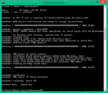
avrdude -p t44 -P usb -c usbtiny -U flash:w:hello.ftdi.44.echo.c.hex
avrdude: AVR device initialized and ready to accept instructions
Reading | ################################################## | 100% 0.02s
avrdude: Device signature = 0x1e9207<
avrdude: NOTE: FLASH memory has been specified, an erase cycle will be performed
To disable this feature, specify the -D option.
avrdude: erasing chip
avrdude: reading input file "hello.ftdi.44.echo.c.hex"
avrdude: input file hello.ftdi.44.echo.c.hex auto detected as Intel Hex
avrdude: writing flash (706 bytes):
Writing | ################################################## | 100% 0.69s
avrdude: 706 bytes of flash written
avrdude: verifying flash memory against hello.ftdi.44.echo.c.hex:
avrdude: load data flash data from input file hello.ftdi.44.echo.c.hex:
avrdude: input file hello.ftdi.44.echo.c.hex auto detected as Intel Hex
avrdude: input file hello.ftdi.44.echo.c.hex contains 706 bytes
avrdude: reading on-chip flash data:
Reading | ################################################## | 100% 0.47s
avrdude: verifying ...
avrdude: 706 bytes of flash verified
avrdude: safemode: Fuses OK
avrdude done. Thank you.
hello.ftdi.44.echo.c
	//
//
// hello.ftdi.44.echo.c
//
// 115200 baud FTDI character echo, with flash string
//
// set lfuse to 0x5E for 20 MHz xtal
//
// Neil Gershenfeld
// 12/8/10
//
// (c) Massachusetts Institute of Technology 2010
// This work may be reproduced, modified, distributed,
// performed, and displayed for any purpose. Copyright is
// retained and must be preserved. The work is provided
// as is; no warranty is provided, and users accept all
// liability.
//

#include
#include
#include

#define output(directions,pin) (directions |= pin) // set port direction for output
#define set(port,pin) (port |= pin) // set port pin
#define clear(port,pin) (port &= (~pin)) // clear port pin
#define pin_test(pins,pin) (pins & pin) // test for port pin
#define bit_test(byte,bit) (byte & (1 << bit)) // test for bit set
#define bit_delay_time 8.5 // bit delay for 115200 with overhead
#define bit_delay() _delay_us(bit_delay_time) // RS232 bit delay
#define half_bit_delay() _delay_us(bit_delay_time/2) // RS232 half bit delay
#define char_delay() _delay_ms(10) // char delay

#define serial_port PORTA
#define serial_direction DDRA
#define serial_pins PINA
#define serial_pin_in (1 << PA0)
#define serial_pin_out (1 << PA1)

#define max_buffer 25

void get_char(volatile unsigned char *pins, unsigned char pin, char *rxbyte) {
   //
   // read character into rxbyte on pins pin
   //    assumes line driver (inverts bits)
   //
   *rxbyte = 0;
   while (pin_test(*pins,pin))
      //
      // wait for start bit
      //
      ;
   //
   // delay to middle of first data bit
   //
   half_bit_delay();
   bit_delay();
   //
   // unrolled loop to read data bits
   //
   if pin_test(*pins,pin)
      *rxbyte |= (1 << 0);
   else
      *rxbyte |= (0 << 0);
   bit_delay();
   if pin_test(*pins,pin)
      *rxbyte |= (1 << 1);
   else
      *rxbyte |= (0 << 1);
   bit_delay();
   if pin_test(*pins,pin)
      *rxbyte |= (1 << 2);
   else
      *rxbyte |= (0 << 2);
   bit_delay();
   if pin_test(*pins,pin)
      *rxbyte |= (1 << 3);
   else
      *rxbyte |= (0 << 3);
   bit_delay();
   if pin_test(*pins,pin)
      *rxbyte |= (1 << 4);
   else
      *rxbyte |= (0 << 4);
   bit_delay();
   if pin_test(*pins,pin)
      *rxbyte |= (1 << 5);
   else
      *rxbyte |= (0 << 5);
   bit_delay();
   if pin_test(*pins,pin)
      *rxbyte |= (1 << 6);
   else
      *rxbyte |= (0 << 6);
   bit_delay();
   if pin_test(*pins,pin)
      *rxbyte |= (1 << 7);
   else
      *rxbyte |= (0 << 7);
   //
   // wait for stop bit
   //
   bit_delay();
   half_bit_delay();
   }

void put_char(volatile unsigned char *port, unsigned char pin, char txchar) {
   //
   // send character in txchar on port pin
   //    assumes line driver (inverts bits)
   //
   // start bit
   //
   clear(*port,pin);
   bit_delay();
   //
   // unrolled loop to write data bits
   //
   if bit_test(txchar,0)
      set(*port,pin);
   else
      clear(*port,pin);
   bit_delay();
   if bit_test(txchar,1)
      set(*port,pin);
   else
      clear(*port,pin);
   bit_delay();
   if bit_test(txchar,2)
      set(*port,pin);
   else
      clear(*port,pin);
   bit_delay();
   if bit_test(txchar,3)
      set(*port,pin);
   else
      clear(*port,pin);
   bit_delay();
   if bit_test(txchar,4)
      set(*port,pin);
   else
      clear(*port,pin);
   bit_delay();
   if bit_test(txchar,5)
      set(*port,pin);
   else
      clear(*port,pin);
   bit_delay();
   if bit_test(txchar,6)
      set(*port,pin);
   else
      clear(*port,pin);
   bit_delay();
   if bit_test(txchar,7)
      set(*port,pin);
   else
      clear(*port,pin);
   bit_delay();
   //
   // stop bit
   //
   set(*port,pin);
   bit_delay();
   //
   // char delay
   //
   bit_delay();
   }

void put_string(volatile unsigned char *port, unsigned char pin, char *str) {
   //
   // print a null-terminated string
   //
   static int index;
   index = 0;
   do {
      put_char(port, pin, str[index]);
      ++index;
      } while (str[index] != 0);
   }

int main(void) {
   //
   // main
   //
   static char chr;
   static char buffer[max_buffer] = {0};
   static int index;
   //
   // set clock divider to /1
   //
   CLKPR = (1 << CLKPCE);
   CLKPR = (0 << CLKPS3) | (0 << CLKPS2) | (0 << CLKPS1) | (0 << CLKPS0);
   //
   // initialize output pins
   //
   set(serial_port, serial_pin_out);
   output(serial_direction, serial_pin_out);
   //
   // main loop
   //
   index = 0;
   while (1) {
      get_char(&serial_pins, serial_pin_in, &chr);
      put_string(&serial_port, serial_pin_out, "hello.ftdi.44.echo.c: you typed \"");
      buffer[index++] = chr;
      if (index == (max_buffer-1))
         index = 0;
      put_string(&serial_port, serial_pin_out, buffer);
      put_char(&serial_port, serial_pin_out, '\"');
      put_char(&serial_port, serial_pin_out, 10); // new line
      }
   }
hello.ftdi.44.echo.c.make
	PROJECT=hello.ftdi.44.echo
SOURCES=$(PROJECT).c
MMCU=attiny44
F_CPU = 20000000

CFLAGS=-mmcu=$(MMCU) -Wall -Os -DF_CPU=$(F_CPU)

$(PROJECT).hex: $(PROJECT).out
	avr-objcopy -O ihex $(PROJECT).out $(PROJECT).c.hex;\
	avr-size --mcu=$(MMCU) --format=avr $(PROJECT).out

$(PROJECT).out: $(SOURCES)
	avr-gcc $(CFLAGS) -I./ -o $(PROJECT).out $(SOURCES)

program-bsd: $(PROJECT).hex
	avrdude -p t44 -c bsd -U flash:w:$(PROJECT).c.hex

program-dasa: $(PROJECT).hex
	avrdude -p t44 -P /dev/ttyUSB0 -c dasa -U flash:w:$(PROJECT).c.hex

program-avrisp2: $(PROJECT).hex
	avrdude -p t44 -P usb -c avrisp2 -U flash:w:$(PROJECT).c.hex

program-avrisp2-fuses: $(PROJECT).hex
	avrdude -p t44 -P usb -c avrisp2 -U lfuse:w:0x5E:m

program-usbtiny: $(PROJECT).hex
	avrdude -p t44 -P usb -c usbtiny -U flash:w:$(PROJECT).c.hex

program-usbtiny-fuses: $(PROJECT).hex
	avrdude -p t44 -P usb -c usbtiny -U lfuse:w:0x5E:m

program-dragon: $(PROJECT).hex
	avrdude -p t44 -P usb -c dragon_isp -U flash:w:$(PROJECT).c.hex
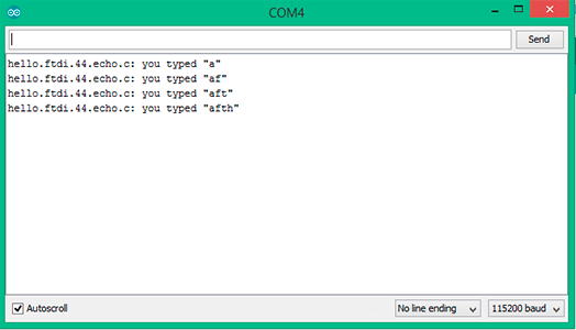
Once I did this, my board was able to be programmed in Arduino so I used the terminal of the Arduino IDE to comunicate with the board and proving that there was an interaction between the board and the Arduino program. I typed letters and the board returned those letters:
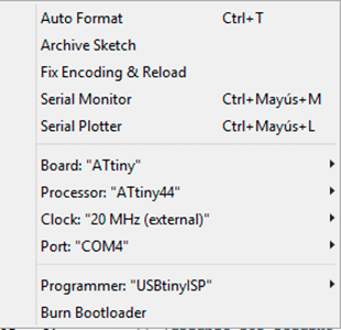
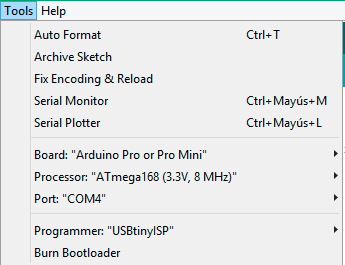
Then I burned the Arduino bootloader in order to program the board from the Arduino IDE: I introduced all the components in my board: the processor (ATtiny44), the clock (20MHz) and the programmer (USBtiny) that I had and of course, the type of board: ATtiny
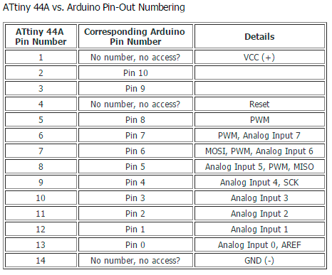
I started programing the light (the blink example) I started with 1000ms and changing the value to see how the program works. I also modified the button program and I understood how Arduino programming works. I had to look for the Arduino names for the processor pins that depends on the bootloader, I look it up in the Arduino tutorials for my Attiny 44.
Simple blink
// the setup function runs once when you press reset or power the board
void setup() {
  // initialize digital pin 7 as an output.
  pinMode(7, OUTPUT);
}

// the loop function runs over and over again forever
void loop() {
  digitalWrite(7, HIGH);   // turn the LED on (HIGH is the voltage level)
  delay(500);              // wait for a half second
  digitalWrite(7, LOW);    // turn the LED off by making the voltage LOW
  delay(500);              // wait for a half second
}
Embedded Programming 1 from msantisteban on Vimeo.
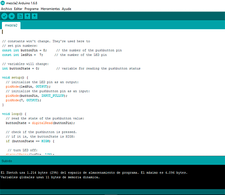
After programming this simple example I decided to complicate it a bit more mixing a button program with the led program.
Simple blink + button
// constants won't change. They're used here to
// set pin numbers:
const int buttonPin = 8;     // the number of the pushbutton pin
const int ledPin =  7;      // the number of the LED pin

// variables will change:
int buttonState = 0;         // variable for reading the pushbutton status

void setup() {
  // initialize the LED pin as an output:
  pinMode(ledPin, OUTPUT);
  // initialize the pushbutton pin as an input:
  pinMode(buttonPin, INPUT_PULLUP);
  pinMode(7, OUTPUT);
}

void loop() {
  // read the state of the pushbutton value:
  buttonState = digitalRead(buttonPin);

  // check if the pushbutton is pressed.
  // if it is, the buttonState is HIGH:
  if (buttonState == HIGH) {

   // turn LED off:
  digitalWrite(ledPin, LOW);


  }
  else {
 // turn LED on:
  digitalWrite(7, HIGH);   // turn the LED on (HIGH is the voltage level)
  delay(300);              // wait for a second
  digitalWrite(7, LOW);    // turn the LED off by making the voltage LOW
  delay(300);              // wait for a second
  }
}
Embedded Programming 2 from msantisteban on Vimeo.
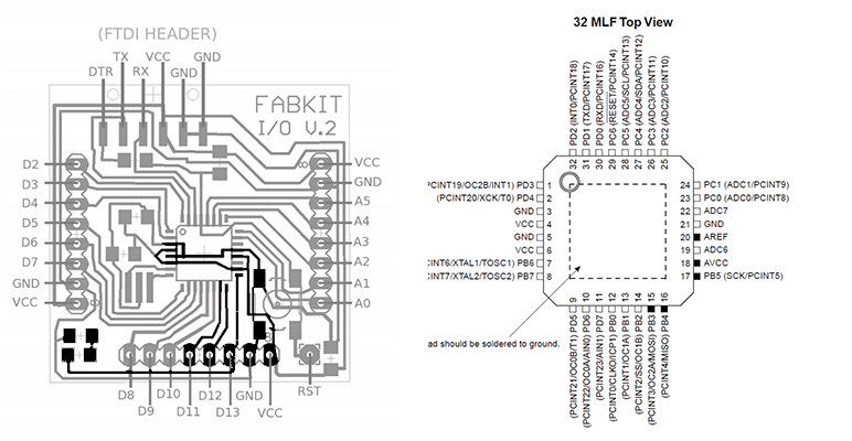
FabKit
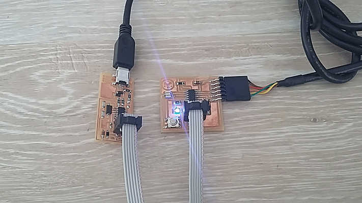
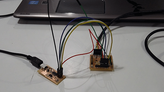
For programming the Fabkit board it was also necessary to connect our board to the programmer made in electronics production: the FabIsp board. I had to connect the ISP pins (5V,GND,SCK,MISO and MOSI) from the FabISP to the Fabkit board. As the processer was different ( ATMega168 ) I had to check the new datasheet in order to see which pins were the ones associated to the programming:
MOSI: pin 15 PB3 (PCINT3/OC2A/MOSI)
MISO: pin 16 PB4 (PCINT4/MISO)
SCK: pin 17 PB5 (SCK/PCINT5)
GND: pin 3,5,21
VCC: 4,6, 18(AVCC), 20(AREF)
Once I knew where I had to connect each wire I connected the FabISP to my Fabkit Fabduino in order to program it. Each wire had a color but the red wire doesn't correspond to VCC neither the black wire to ground, that is to say that the colors are just to distinguish them.
I decided to program it Arduino so I followed the tutorials for being able to upload the bootloader to the board. It was really easy to burn the bootloader. As the button in the Fabkit it’s only for making a reset, I couldn’t program the button but I could program the led. In this board as the processor changed it changed also the pins connected to the led and button so I had to do the same thing with the Hello board: look in the tutorials what were the names that Arduino understand for each pin. It is not the pin name of the datasheet; it depends on the bootloader and its configuration.
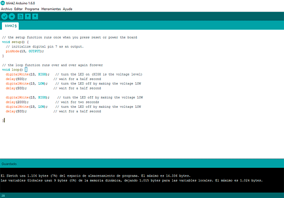
In the LED program I wanted to do something different than the other program in the hello world board, I added a blink: I wanted the led to do two blinks: a half second blink and a 2 second blink. I founded that the led was connected to pin number 17 in the datasheet that correspond to the IDE pin number.
Simple blink + 2 second blink
// the setup function runs once when you press reset or power the board
void setup() {
  // initialize digital pin 7 as an output.
  pinMode(13, OUTPUT);
}

// the loop function runs over and over again forever
void loop() {
  digitalWrite(13, HIGH);   // turn the LED on (HIGH is the voltage level)
  delay(500);              // wait for a half second
  digitalWrite(13, LOW);    // turn the LED off by making the voltage LOW
  delay(500);              // wait for a half second

  digitalWrite(13, HIGH);    // turn the LED off by making the voltage LOW
  delay(2000);              // wait for two seconds
  digitalWrite(13, LOW);    // turn the LED off by making the voltage LOW
  delay(500);              // wait for a half second

}
Embedded Programing 3 from msantisteban on Vimeo.
FILES:
Hello Board:
Fabkit Board: