
MachineBuilding_v4 from Marta VerdeonVimeo.
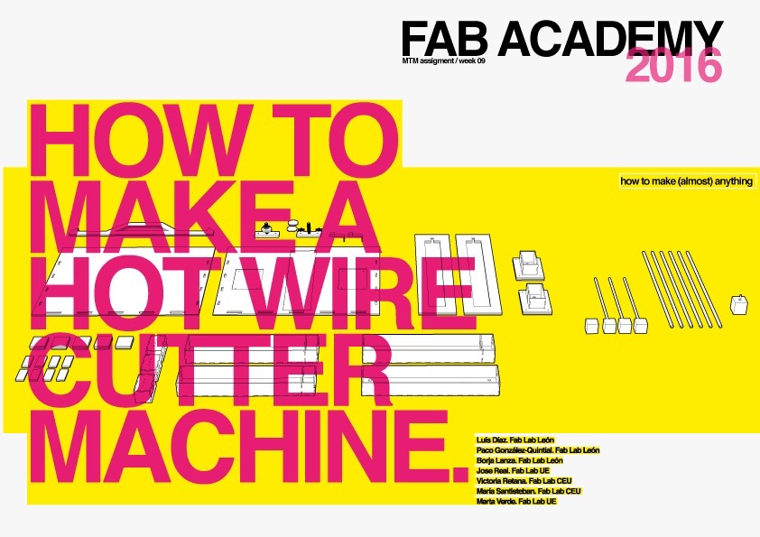
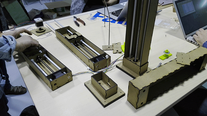
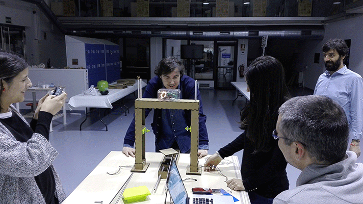
This week's assignment was about making a machine, including the end effector. First, we had to build the passive parts and operate the machine manually, and then, we had to automate it. Four different FabLabs decided to get together in Leon in order for us to do the MTM machine. Our machine is designed to work with three axes of motion, one of which can also rotate. It is also designed so that it can be portable and it can be kept in a suitcase.
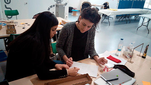
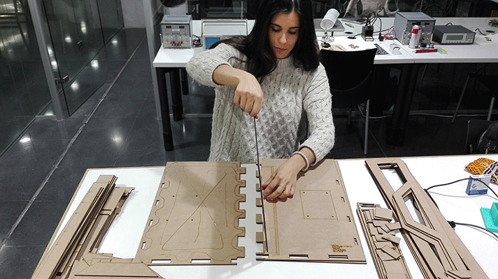
We divided the work in two parts: The construction and assembly of the different parts and the programming. As an architecture student I did the construction and the assembly of the different parts with Francisco González-Quintial, Jose Real Cambas and María Victoria Retana.
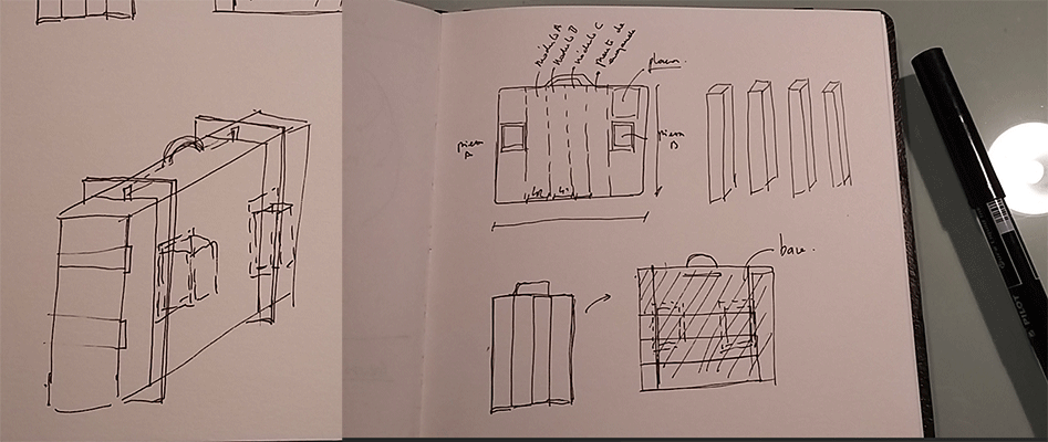
As we wanted our machine to be portable one of the main concerns was how we were going to keep our machine in a suitcase and we came to the conclusion that each module should be a separate part of our final model hooked together in an easy, quick and simple way.
So we did some sketches of how we wanted our suitcase to be and the different parts that conform our machine in order to reach the desired model: we wanted our machine to be practical.
We design the connection piece between the base and the respective modules of the vertical axes. This piece would support the different structural efforts. Therefore this part would be anchored in some way to the base so that it was not necessary to assemble the piece whenever we wanted to use our machine. It was designed from the beginning to be printed in 3d with the makerbot replicator 2 but the printer started giving problems and we had to redesign it in order to be printed laser cut machine.
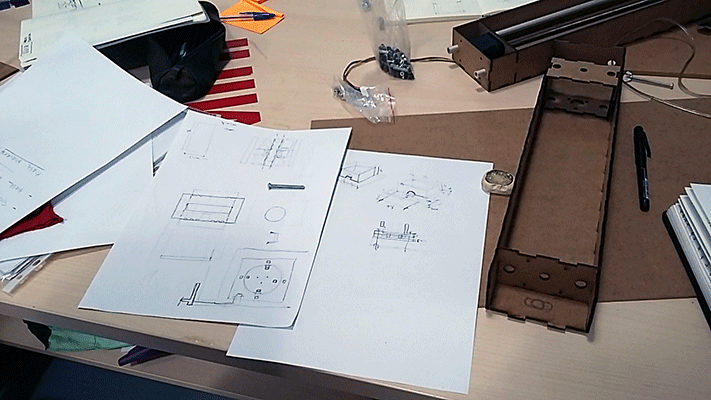
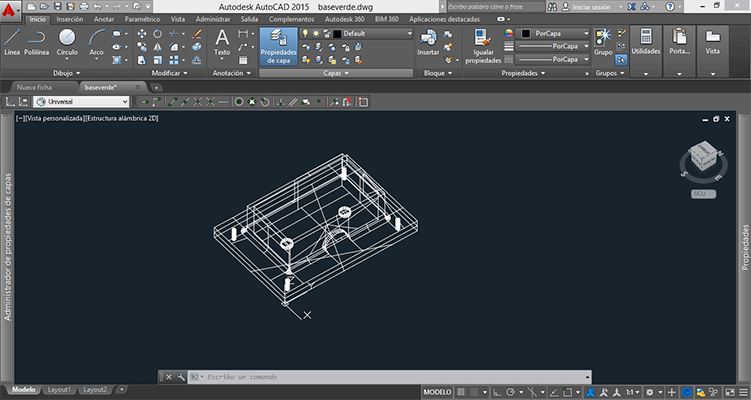
After thinking how would it be this piece what I did was making a model of it in 3d. I used Autocad for making the 3d model because it is the modelling program I know best. As you can see in the image, the piece is designed to be anchored to the base by four holes located at the corners. This piece was the union of the modules to the base, we made a half-circle -shaped hole for motor wiring and another two holes for the tubes that guide the movement of the hot wire that are located inside the modules.
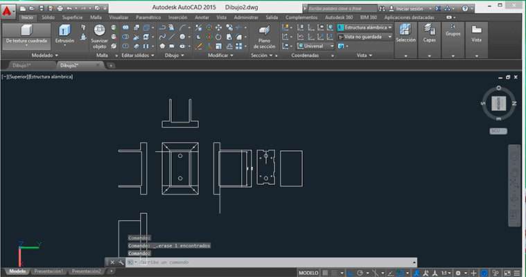
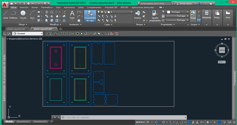
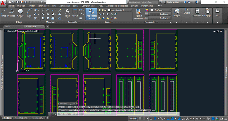
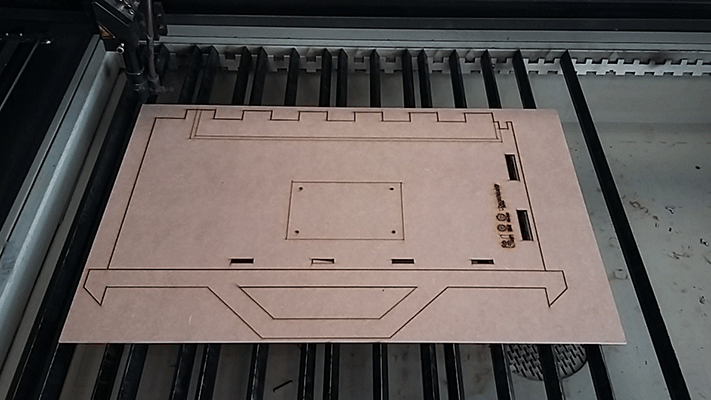
As the piece took so long to be printed on the 3D printer, what we did was to redesign it again in order to be cut with the laser cut machine with an MDF board of 3mm. As we had the 3D model, all I had to do was drawing the plans. Once all the parts were cut I set the piece.
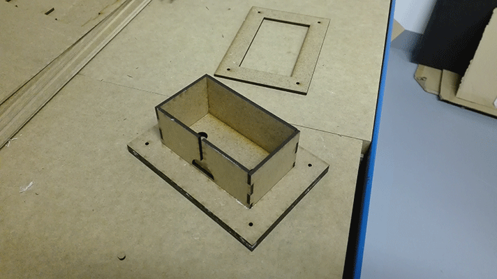
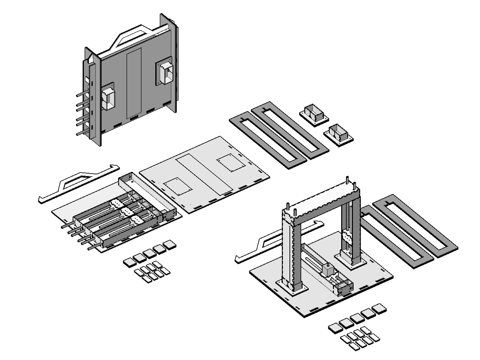
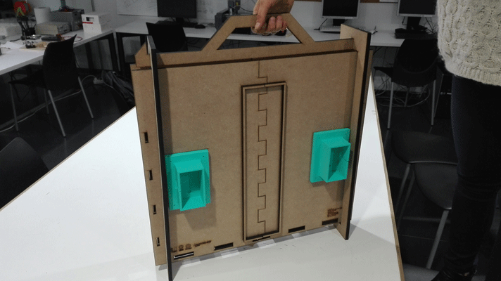
As you can see in the image, the structure of the Mc Nulty Machine fits perfectly into this pieces.
The suitcase
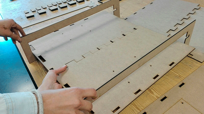
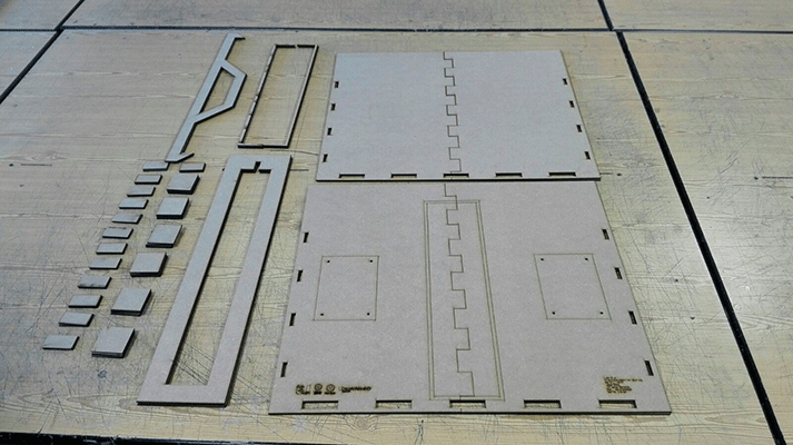
Once we set up the structure of our machine with all its parts and its anchorages the next step was making the suitcase. The image shows perfectly how the suitcase is and all the different parts kept in it.
What we did was cutting and assembling the pieces that made up the suitcase with an MDF board of 3mm for all the parts of our suitcase. We also designed the plans in Autocad. We had to split the cover of the case into two parts as we could not fit it into the MDF board so each cover is made up of four different parts with a thickness of 6mm
Doing the suitcase with an MDF board resulted to be a bad idea because we didnt thought about the weigh. The suitcase resulted to be very heavy and not that usefull. I think this could be improved with another type of material.
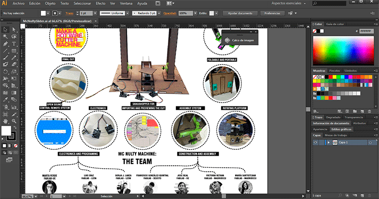
I was also in charge of doing the machine's web page. I gather together all the information given by my group collegues in order to organize it and express it in the machine's webpage. I also designed the machines slider in illustrator.
FILES: