Computer-controlled machining
Assignment for this week
- Make something big!
- Use one sheet of sheet of plywood- 15mm thick,1220 x 2440 mm
- Learn how to work the Big milling Machine -The ShopBot
- Learn how to use VCarvePro
- Link to this week’s home work page
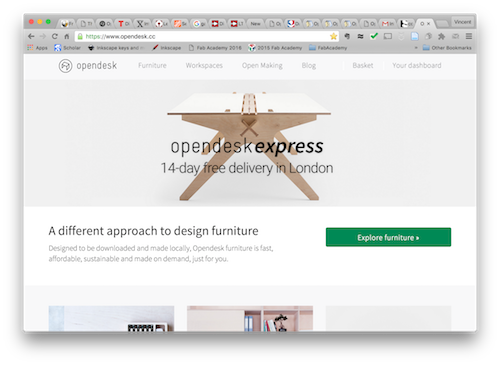
Make a big 3d object from the assembly of 2d pieces. After Neil's lecture, I went to opendesk to see what kind of furniture people were sharing under Creative Commons licenses. There it is possible to download .dxf design files and assembly instructions for a given piece of furniture or it is also possible to order it from local makers.
This page is organized as follows:
- Autodesk 123D Make
- My parametric design of a shelf
- The Shopbot
- Unmounting and remounting the tool
- Fixing the wooden board and zeroing
- Preparing for cutting: VCarve
- Making something big
- Production and assembly
Autodesk 123D Make
I also tried Autodesk 123D Make that can slice .stl 3d objects and produce a set of 2d parts that can be assembled into the 3d origin object. I made some tests but should come back to this later.
I also had a look at what the 2015's students made and found some quite amazing stuffs but certainly too complicated for my present knowledge. I decided to make something simple: a shelf.
My parametric design of a shelf
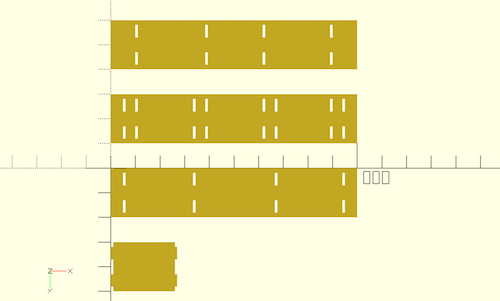
Since I anticipated several ajustments (tickness of the wooden board, machine parameters, etc...), I prepared a fully parametric design of a shelf in OpenSCAD.
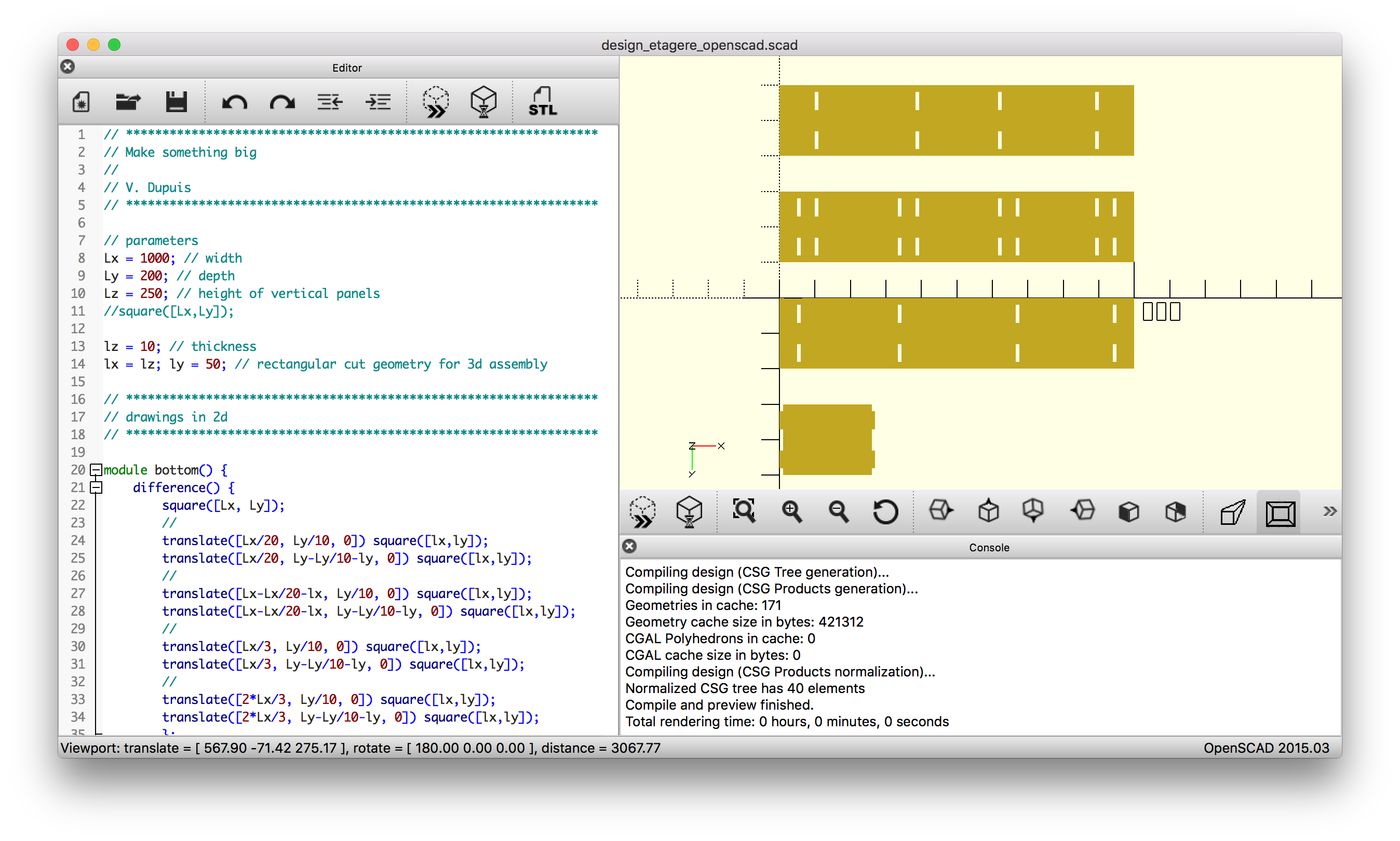
I used press-fits initially rectangular shaped of 10 mm x 50 mm.
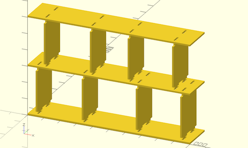
To get a better idea of the shelf, I made a linear extrusion of 10 mm along the z direction (with the command linear_extrude(height = 10)) and made a 3d assembly of the design.
The Shopbot
Since there is no Shopbot at Fablab Digiscope, we went to Fablab Descartes thanks to its Fab Manager Mathieu Poncin who is also a FabAcademy 2016 student at FabLab Digiscope.
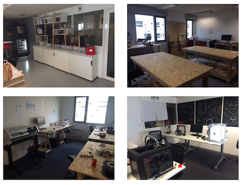
There is a Shopbot buddy standard there and Mathieu who is already an expert with the machine kindy accepted to train us.
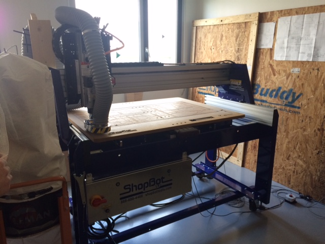
The shopbot is a big machine, quite impressive at first.
Unmounting and remounting the tool
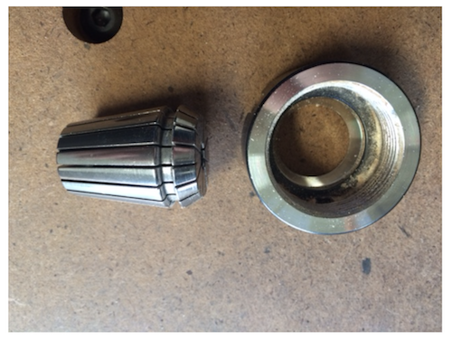
Mathieu showed us how to unmount/remount a tool. First remove the dust collection head and loosen the part that contains the collet (use one hand and two keys). Remove the milling head from the collet and remove the dust from the collet.
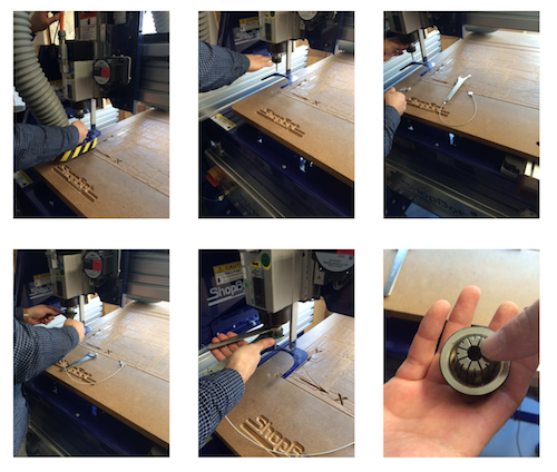
The collet (which is different for the different tools) can be removed from it holder with a slight push.
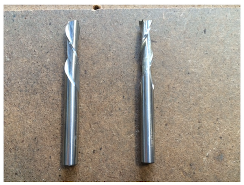
Mathieu showed us two types of milling head (on the left the one used for upcutting and on the right the one used for downcutting, rotation is clockwise). For my design with 10 mm tick wooden board I'll be using the downcut milling head (1/4" - 6mm) one since it's better to push down on the material while cutting.
Remounting the tool. Insert the milling head and stop 5 mm above the filet. Tighten with one hand. Place the dust collection head so that its hair are in contact with the wooden board.
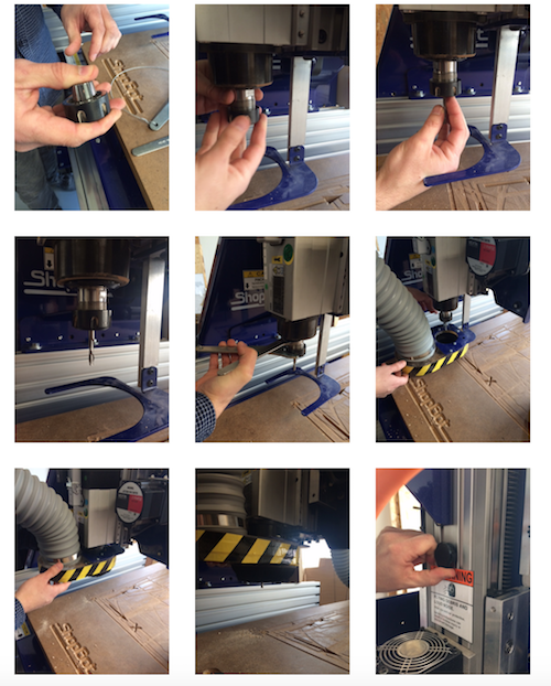
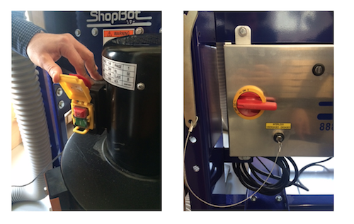
The dust collection can be turned on/off with a button (left), the machine too (right) and a key must be turned for the spindle to be turned on (this is controlled by the computer).
Fixing the wooden board and zeroing
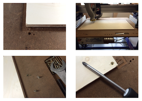
To fix the wooden board on the machine bed, we used screws.
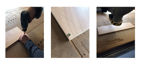
The milling head can be moved along X, Y, and Z using the Command Software on the computer.
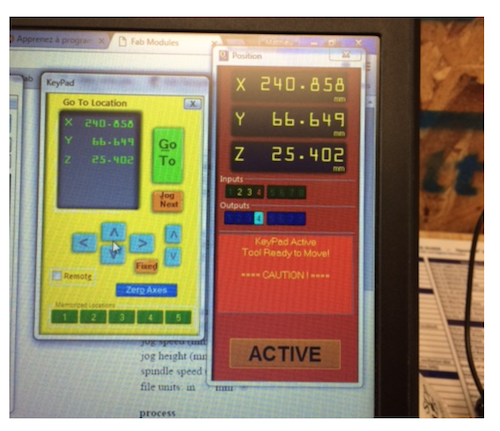
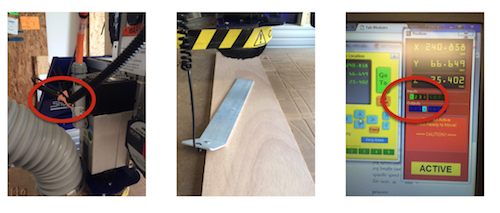
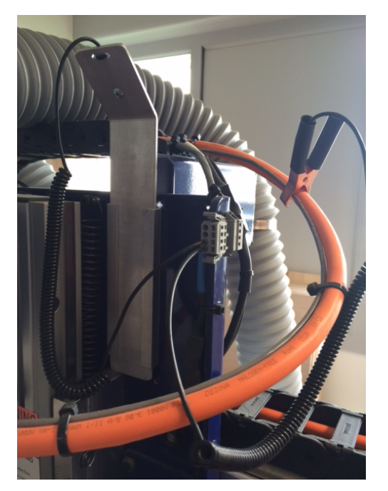
X,Y zeroing is easy as there is a button that just does that for the user automatically. Z zeroing requires more work. We use a crocodile clip that we clip to the ground and and metallic plate connected to a sensor. Once the milling head gets in contact with the plate the sensor sends a signal and an indicator (#1) turned green on the computer screen.
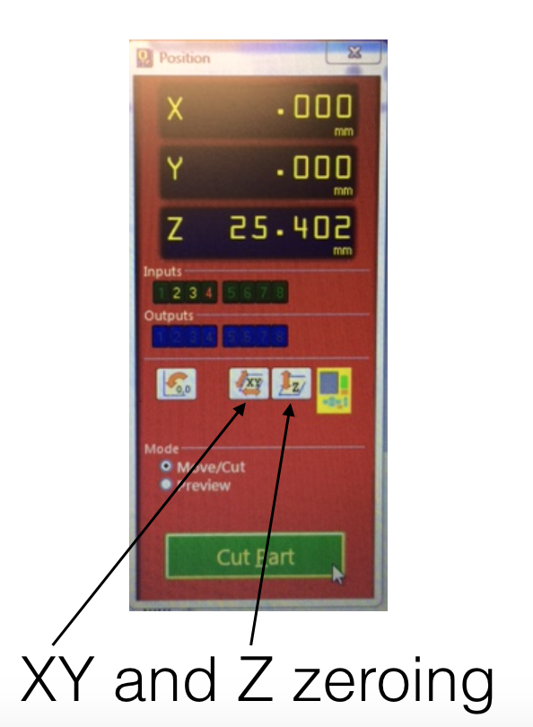
The Z zeroing process is done by clicking on the Z zero button. (the most left button is used to go back to X=Y=0). The head goes down slowly and stops once contact between the milling head and the plate is detected. The operation is repeated twice.
Once done, do not forget to replace the clip on an insulating part of the machine and the plate back in its holder.
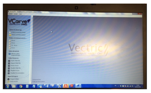
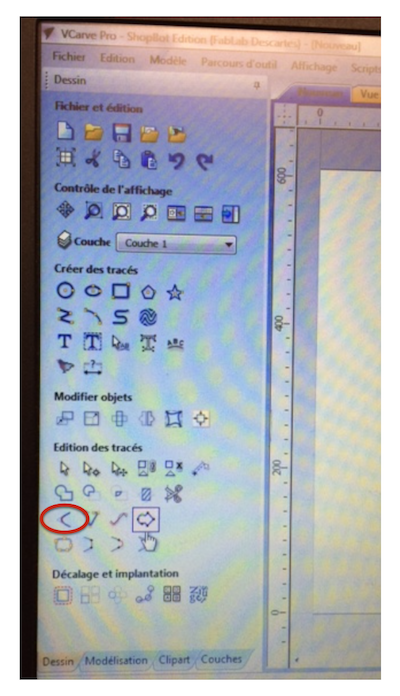
Preparing for cutting: VCarve
We tried the Fab Modules but we could not generate a valid command file (why is not clear and our Instructor at digiscope will solve that in the near future). We thus decided to use VCarve from there to create or import a design (.dxf but also svg or images).
- spindle speed = 14000 rpm
- 2 passes of 10.6 = 5.3 mm (less than the 6 mm milling bit diameter)
- feed = 50 mm/sec
- plunging speed = 70 mm/sec
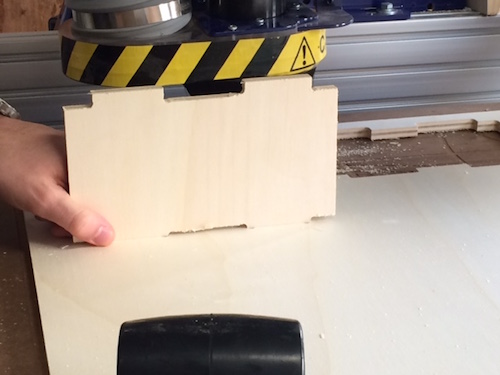
Mathieu showed us quickly how to create a rectangular hole for press-fit.
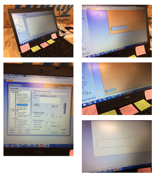
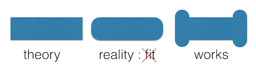
He explained the necessity to use round angles (T bone like) for a rectangular hole to be used for press-fit assembly. Without that, the wooden board would not fit in the hole.
Then we started the cutting.
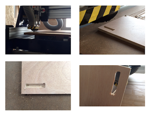
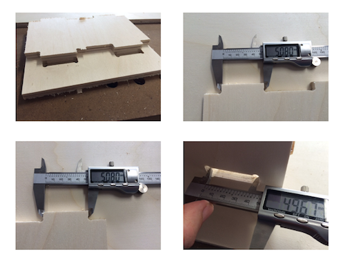
After measuring the hole we noticed a discrepancy of 1% between the dimensions of the design (10 mm x 50 mm) and the result obtained (9.90 mm x 49.6 mm). This mean that we will have to scale the design to 101% !
Making something big
The goal is to make this.
I will make a test with the real wooden boards (120 cm x 60 cm soft poplar plywood chosen the less bent possible although stored vertically at the shop). The thickness was supposed to be 10 mm. I measured it to be 10.2 mm so I had to correct the design. I was happy to have a parametric design.
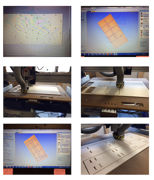
Importing the .dxf design in VCarve.
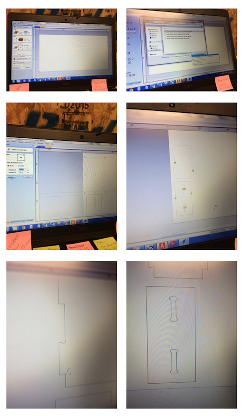
I had to round the 90 deg angles.
I used the 2D Profile Toolpath, Start Depth (D) 0.0 mm and Cut Depth (C) = 10.6 mm had to add Tabs (Tabs > Add Tabs to toopath) and move them a bit and I used a ramp for downcutting with a plungin speed of 70 mm/s. I saved the toolpath (don't forget to select it) as a .sbp files that can be read by the ShopBot command software. Before cutting, one can simulate the toolpath by setting the Offset in 2d-3d to 3d offset. The milling head then move at 1'' above the surface. If everything is ok, on can stop (by hitting SPACE), quit, clicking on go to zero and relaunch the Cut Part (with no offset this time).

And .... it does not fit because I forgot to rescale the rectangular hole to 101% !
I made the change and just recut two rectangular hole and it worked !
Production and assembly
Everything set up. I finally started cutting the final parts for the shelf (I separated the part by 3 times the milling bit diameter).
Finally after cleaning a little bit and assembling parts,
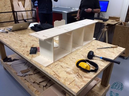
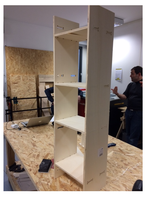
I didn't have time to finish the whole shelf but it's ok. Now I know how to do it.