Final Project
Step 3
In this section I will present the work I have done on the electronic and mechanic aspects of my final project.The mechanical aspects of my final project are related to the minutes display system of the clock. As explained in the Idea and Design sections, I decided to display the minutes on a spinning circle : basically it will be a kind of wheel on which I will attach an LED. The postion of the LED will indicate the amount of elapsed minutes, acting just like a hand on a regular clock.
 So the main interconnected questions I had to answer were :
- How to design the wheel so that it fits in the inside of the clock and how will it turn ?
- How can I power the LED which will be attached to the wheel, if the wheel is turning ?
- How will I control the rotation speed and angle to have the right position ? >
1. Designing the wheel
In my opinion the best way to proceed was to use gears. I would have a large gear for the wheel itself, and a small one, connected to a motor to make it turn. I found the perfect tool to help me designing this on this website. I already talked about Gear Generator during Week2 but Involute Gear has a very useful feature for me : it allows to make internal gears, which is exactly what I will need : I will probably use a LED matrix to display the weather forecast on the center of the clock so I will need a lot if space and a regular gear would take to much.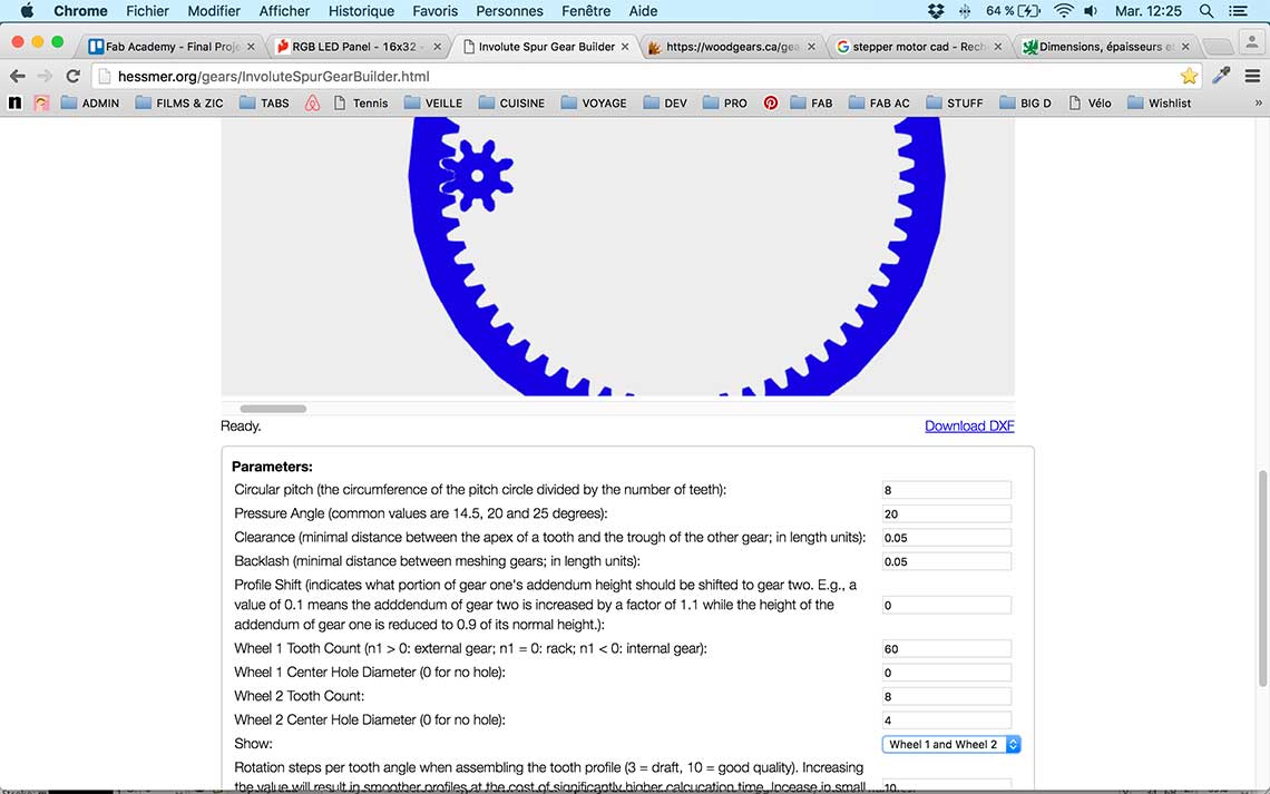 With an internal gear I will be able to save some space inside the clock, which a really good point. One my gears were generated in the app, I just had to download the dxf file, import it into Rhino and turn the curves into polysurfaces :
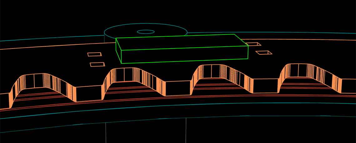
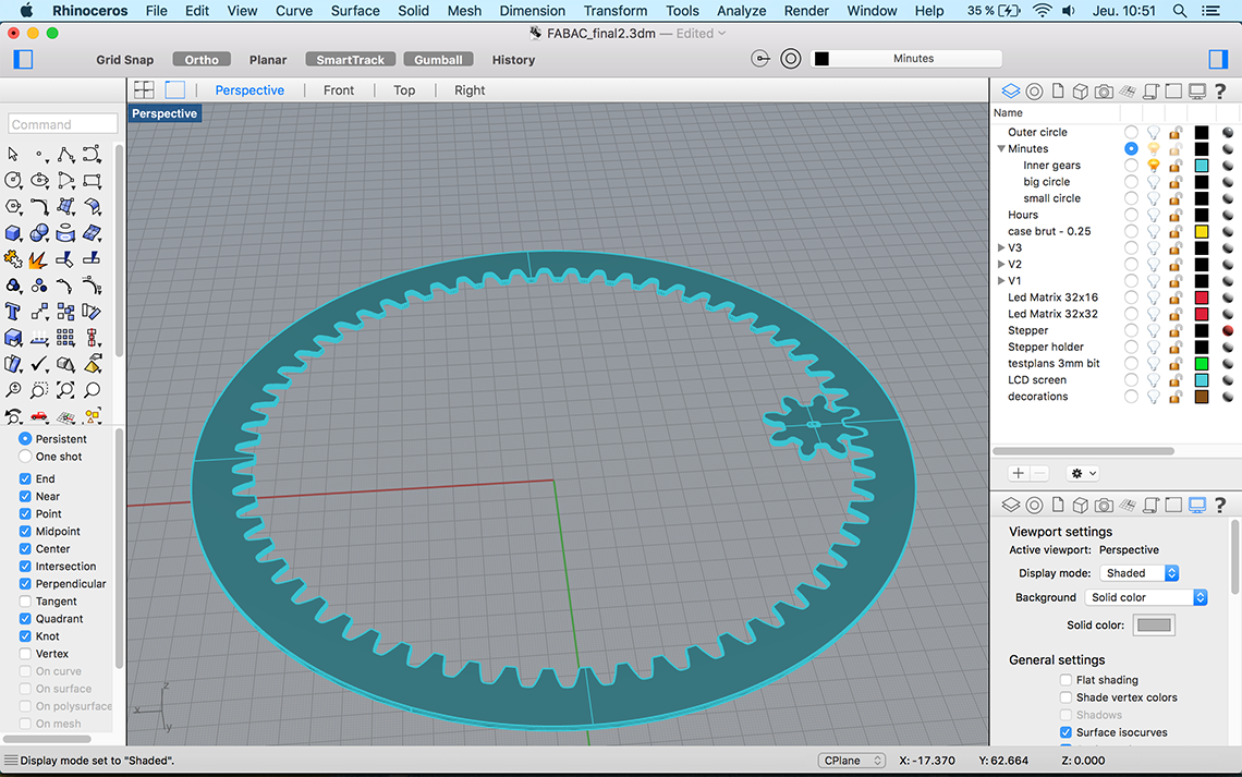 Here is a view with the actual circle I'am planning to add on top of the wheel, to hold the minutes LED, represented by the orange indicator :
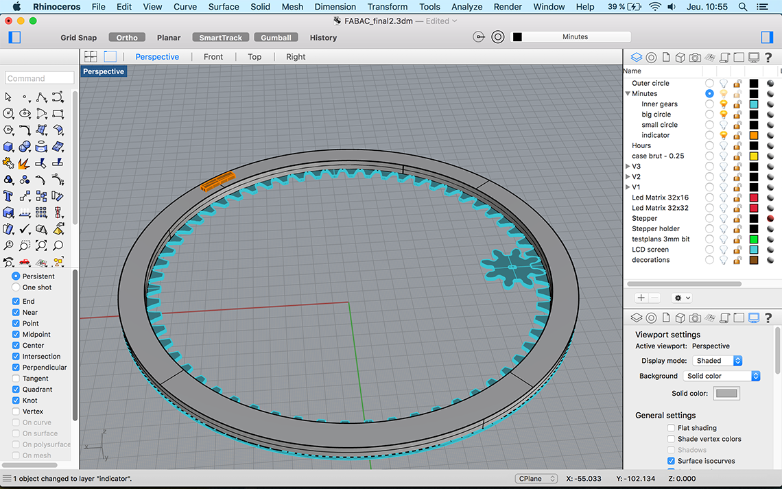 To make the small wheel turn, I was planning on using a stepper motor or a continuous rotation servo motor, but I'll cover this later in this page...
Then the tricky part was to find a way to hold the big wheel in place, given that there is no central axis ? For that I had to design a kind of "case", with small wheels to make the big one turn easier :
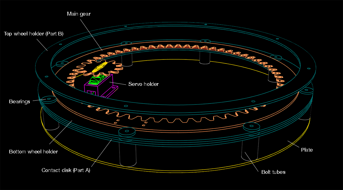
Here is an "exploded" view of the system :
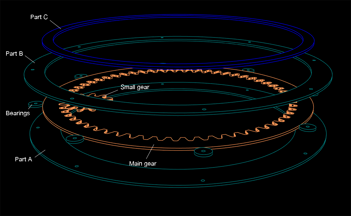 The main gear will rest between Part A and B and will be held in place by the bearings which will also make it turn easily. The holes for the bearings are for M3 bolts.
The small gear will be directly connected to the head of a servo motor.
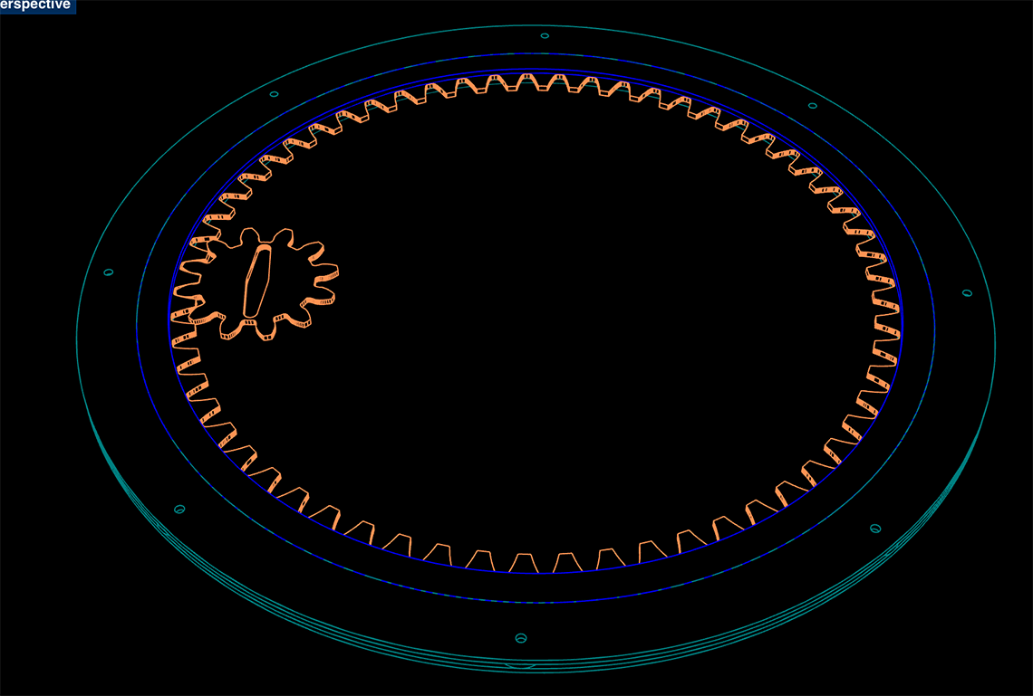
Here is the non exploded view of this system :
 And with the dimensions :
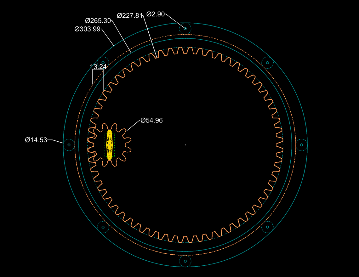 Then even most tricky is, how will I power the LED ? This leads me to next part :
2. Powering the rotating LED
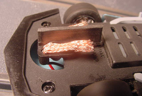
When I say "powering" the LED, I mean, connecting it to the microcontroller I will use to pilot it.The conventional and easiest way would be to use wires that would be long enough to follow a 360° rotation but this would be a bit messy and certainly get in the way of the LED matrix or other components I will need.
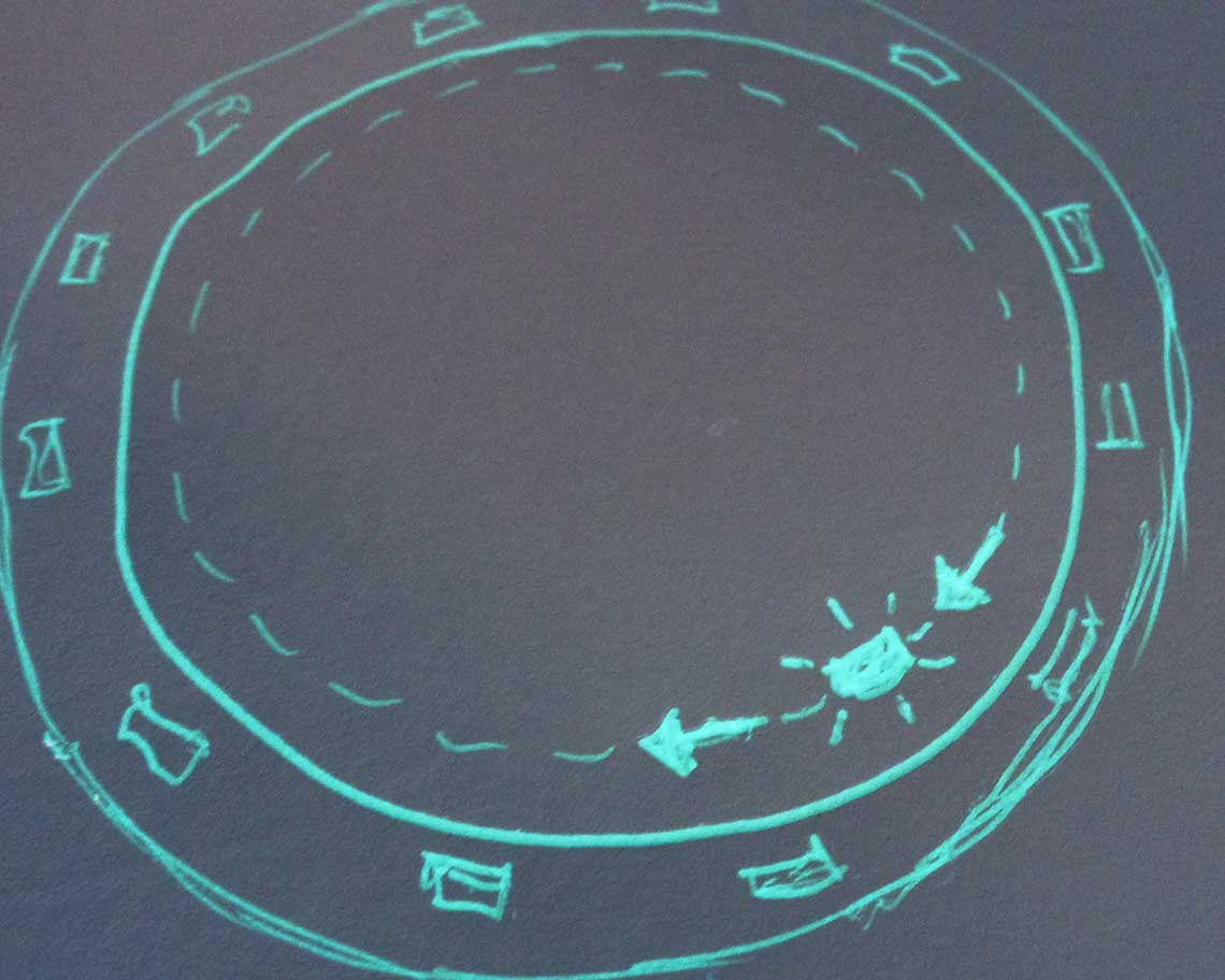
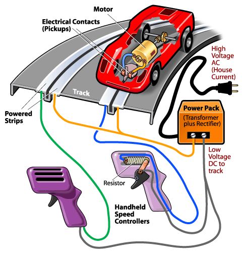
So I had the idea of using the same technique as for slot cars : On the top surface of Part A and on the bottom surface of the Main Gear, there will be copper traces touching each other, in order to conduct current to the LED which will be place on Part C..
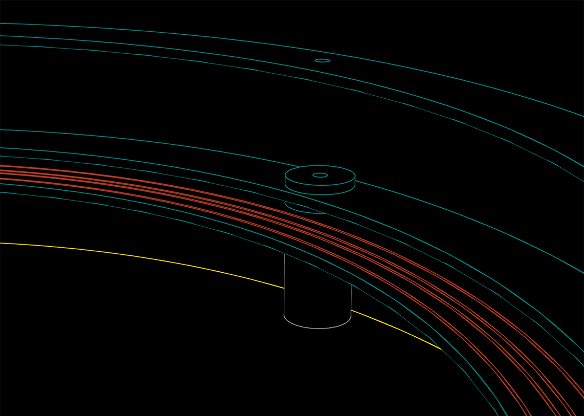
Here is an update of the 3D design :
 The top and bottom wheel holders are here to maintain the main gear in place, allowing it to rotate freely. So there is a space between the gear and the "contact disk" on which the copper traces are placed :
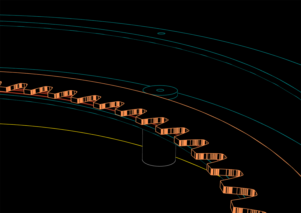
FEATURE ABORTED - SEE ELECTRONICS PAGE