Weeks 9 and 10: Machine design and automation
As this was a group assignment and our supernode Fab Lab León hosted a weekend session for all the students to meet and work on the machine: McNulty Machine
MachineBuilding_v4 from Marta Verde on Vimeo.
The Weekend:
I got a little late to the MTM session at Fab Lab León, not really late, but some of my colleagues arrived León on Friday and started setting up the tasks and started setting up the boards. So on Saturday morning when I got there Marta and Borja were already connecting the boards. They’ve never used a laboratory power supply with voltage and current regulation so I explained them a little bit on current limiting and voltage supply.
As Fab Academy 2015 students also met at León for the MTM assignment, the FTDI cable, connection board and cables were already made. So we started installing Python and required dependencies like Pyserial and Pygestalt on our computers to test the boards. When we first run simple_node.py from Pygestalt examples, we were able to connect to serial but then the LEDs won't start to blink and ask for identification on the bus.
We wanted to discard a problem with the firmware and practise with programming firmware into the avr from different OSs. So we had two firmwares available 086-005a.hex and 086-005a_boot.hex and we were seeing that different labs used different hexes selected as the “working ones”. And after a while having problems also after flashing (rewriting fuses then burning the firm… test, nothing) I decided to disconnect everything and start fresh re-checking connections, power supply and firmwares.
That’s when we discovered a cable in the wrong position that gave us hope. So we plugged everything right, flashed all four (by that time labeled) nodes and started single testing each one of them. To our surprise, two of them (#1 and #4) worked but the other two didn’t and showed a message on the console “RUNNING IN BOOTLOADER MODE” while the working ones showed “NOW RUNNING IN APPLICATION MODE”. So we reflashed boards #2 and #3 with 086-005a_boot.hex, repeated the process and everything worked. We run the single_node.py for every board and motor and discovered that one of the motors was vibrating when stopped, so we discarded that the board was the fault, and changed the motor as we only needed 3 motors with an axis.
The next step was to get all four motors working and then check on the power consumption and see what power supply was needed once we install a dedicated power supply. The consumption will depend on the load, weight to move and speed. At speed 2, and without any foam on the plate, the consumption was around 0.88 A which seems very low and gives us room to use a 5A supply for all motors and the nichrome wire.
Now the electronics were set up, we focused on getting a simple code to be able to test the cutting before leaving León. There was some documentation foam cutting machines from last year that we’ve been following during the weekend. But we wanted to start in the middle from scratch to a fully working version for a very similar machine. So we picked xy_plotter.py example from pygestalt htmaa machine example. Since we can still work on the code and improve it, and even for distributed programming while we were there, we set up a git repo at Gitlab, but not git.fabacademy, but gitlab.com. Later we realized that we have to have it on the fabacademy archive.
About the name, when I've started the GitLab repository, thinking of it as something just to share code while we were on the Fab Lab, I put the name McNulty one of the main characters on The Wire tv series as a pun, since we were building a hot wire cutting machine. Monday when we got back to our weeklife, as nobody proposed any other name, it became McNulty for the machine too.
After the weekend
So we went back to our lives and started the documentation process as well as continuing with the programming of the machine. I wanted to do my part in the programming, and file input rather than machine movements. And I didn't even have the machine available for testing during the week because it was 150Km away. When David and I were using digital fabrication for UAVs, we always wanted to do a big hot wire cutter to be able to fabricate one piece wings out of foam.
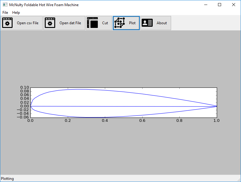
During this time we used Airfoiltools.com a lot when designing wings, stabilizers and any other part with an airfoil. We used .svg then .dxf most of the time but the original data I remembered was just a couple of rows of coordinates for a 1 unit chord airfoil.
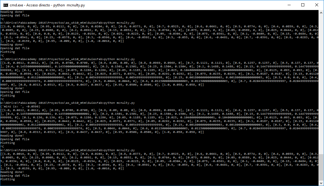
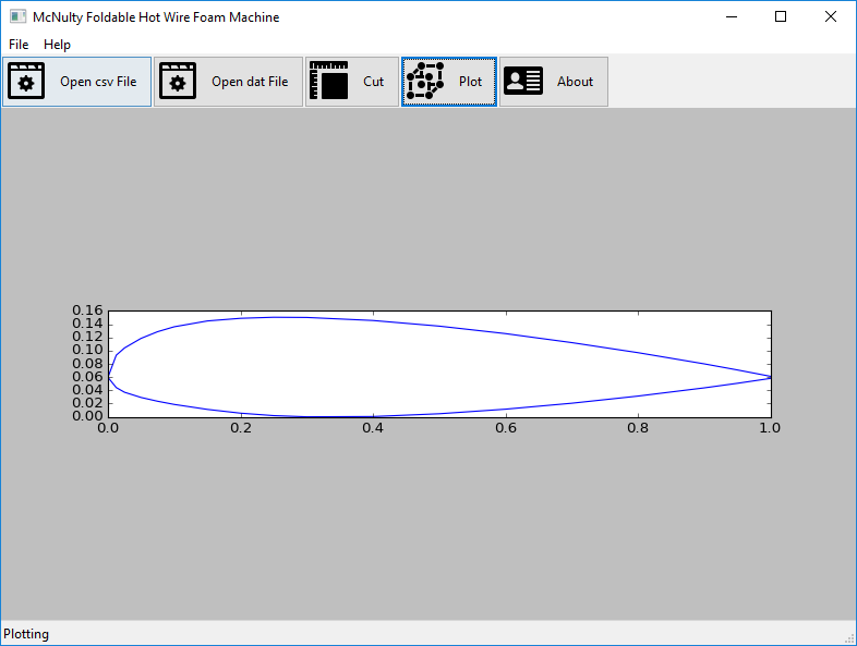
Another thing that could enhance the GUI was a plot graphic so one can figure out what kind of movement the machine is going to make before sending. That is a nice basic feature I like from other machines softwares, the cut preview. So I researched a bit about graphics for python and wx and found matplotlib, a library intended mostly for mathematical plots, but that could be useful for what I wanted. So after testing a bit I got the first plot, all deformed but something on the screen. From that, I had to fix aspect ratio, then offset so no coordinate would be negative and implement a scale function so the size can be chosen from the interface. Additionally, I fixed a couple of bugs referring to how the coordinates were stored.


Another personal contribution was taking the whole project to GitLab, I considered this a good example of real distributed development that could take us to some interesting features of Git. I was planning to move it the week of the presentation to Fabacademy's GitLab but then were problems of the Git going down and I feared to feed the problem, but I plan to leave it on the course repository in the next few days.
Future improvements would be to have a complete wing designer, so other parameters rather than chord such as inner chord and tip chord, attack border angle, escape border angle... So you would have a wing cutting software for any MTM machine.
Screencast of the wing cutting process, including downloading .dat from Airfoiltools.com
Files
All the design files generated by the team during this assignent can be found here