Week 17: Applications and implications
I'm a little bit nervous because I have not yet committed to a final project, I have several ideas but didn't select one yet. The "Soundflower" caught my attention after composites practice, but I still have to mount a microphone to test its functions.
I've picked this week what it will be the final project. I changed it from a vest for cyclists with turning and brake lights to a project I'm gonna call "Soundflower" which is a microphone with a parabolic reflector that moves looking for subtle sounds.
How will others be able to make your project by reading your documentation?
I don't think I get this question, I mean, by getting dirty on a Fab Lab and following the instructions. If we are referring to what those instructions will be I find that a combination of video and text with pictures works great. So you can get a global idea of the process in the video but when you need to stop and get detail of something you have the pictures to refer to.
All files needed to make and modify this project will be available both as ready to fabricate files or design files. For instance, all 3D part will be available as SolidWork files for anyone to see how they were designed and modify them and as STL files ready for printing or milling just as I will do.
What will it do?
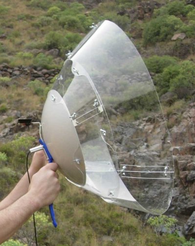
The Soundflower is a parabolic microphone that automatically searches for sounds around it. Just like a sunflower turns to be facing the sun, the SoundFlower will turn around on the horizontal plane trying to get as much input sound as possible. The SoundFlower can be placed in remote spots (like a mountain or a forest to automatically search for sound sources.
Who has done what beforehand?
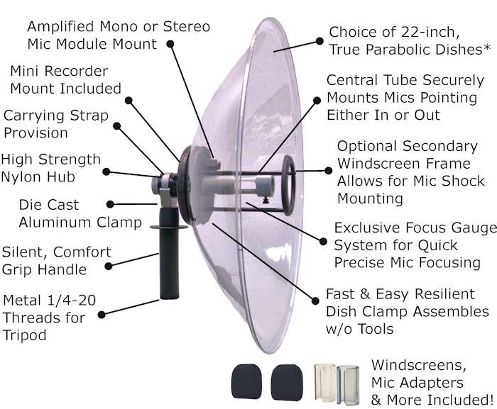
Parabolic microphones are widely used when having a very directional and sensitive response is needed. Examples of use involve sports, espionage and nature observation. They are sold commercially for multiple purposes from more professional to educational toys.
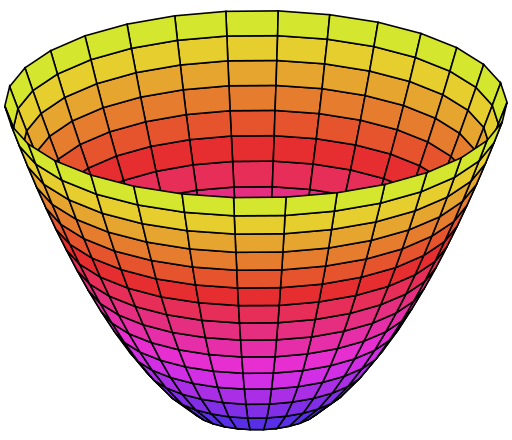
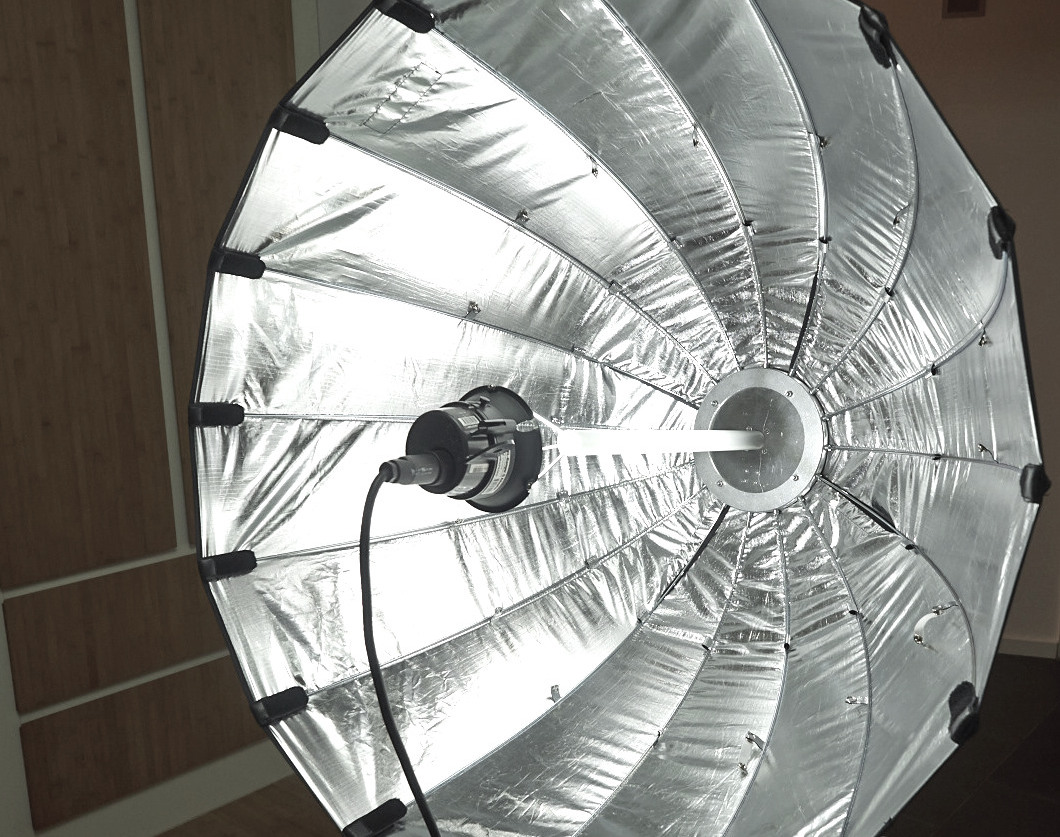
Moreover the parabolic reflector is quite interesting whenever working with any kind of rays. Parabolic reflectors are the surface of a paraboloid, which is the surface you get when you revolve a parabola around its axis. It has the great property of getting every ray coming parallel to the parabola axis to rebound to a point, same for all, called focus. That means that signals coming from far away will be focused on one point, and signals coming from the side will be rejected. So parabolic reflectors have lots of uses ranging from RF to heat or audio.
Most extended use of parabolic reflector would be parabolic antennas, well-known around the world for getting satellite TV signals among a lot of different applications. Satellite TV antennas are fixed to a certain point on the sky. What happens here is that geostationary satellites will keep relative position to earth, so they appear to be still from the ground, hence you can point your antenna and get those signals. Most of this reflectors are off-axis meaning that they're not the central part of the parabolic surface, but a "side" and the focus will be closer to the edge. This is done like that for satellites because that allows placement of the receptor and it's holding arm out of most input rays having less shadow and better reception.
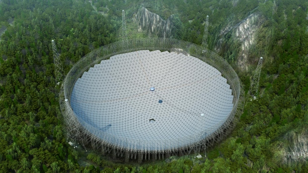
But when it comes to big parabolas, for big distances, space exploration is the application. In fact this year is planned for the largest radio telescope to become operative, the FAST in China. And the "F" stands for Five-hundred-meter which is the diameter of this huge antenna that reflects signals from almost 200 000 square meters. As you may see in the render picture below, it is composed of 4600 triangular panels.

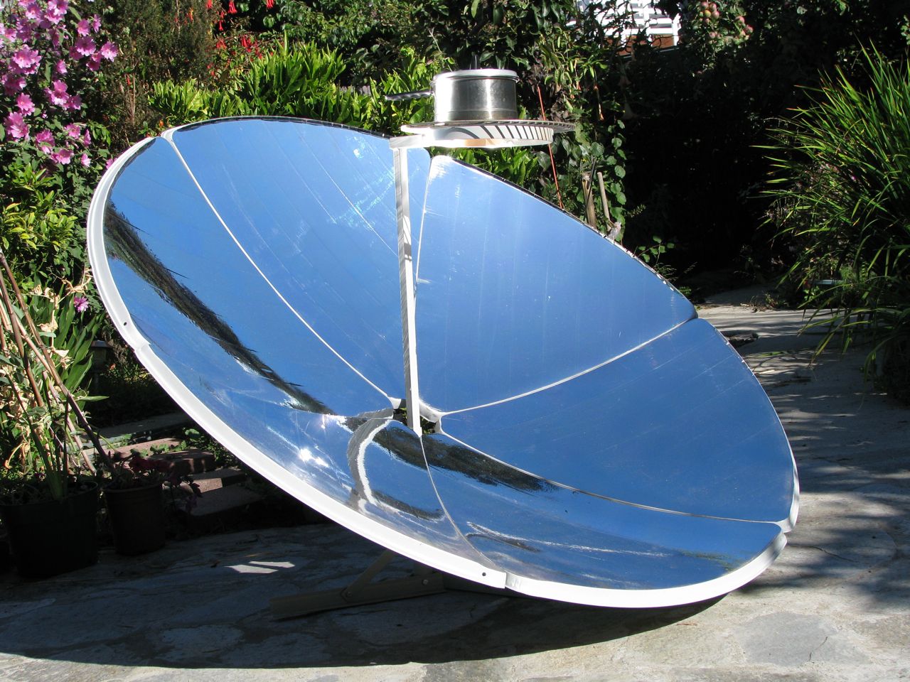
But when it comes to rays coming to the earth, sun rays were there before we got our satellites around the earth. But those rays are mainly light. There are lots of projects using sun rays and parabolic surfaces. Solar ovens (or solar cookers) are well known for development areas because energy comes completely free, so there's no need to burn anything. Solar ovens are not always parabolic, and even parabolic ovens are made from different sections. That's a way to control temperature, the more accurate the parabolic surface, higher temperature can be reached in a smaller point, the less the accuracy and you get less temperature (but can be enough to boil water) in a larger "focus" the size of a pot for example.

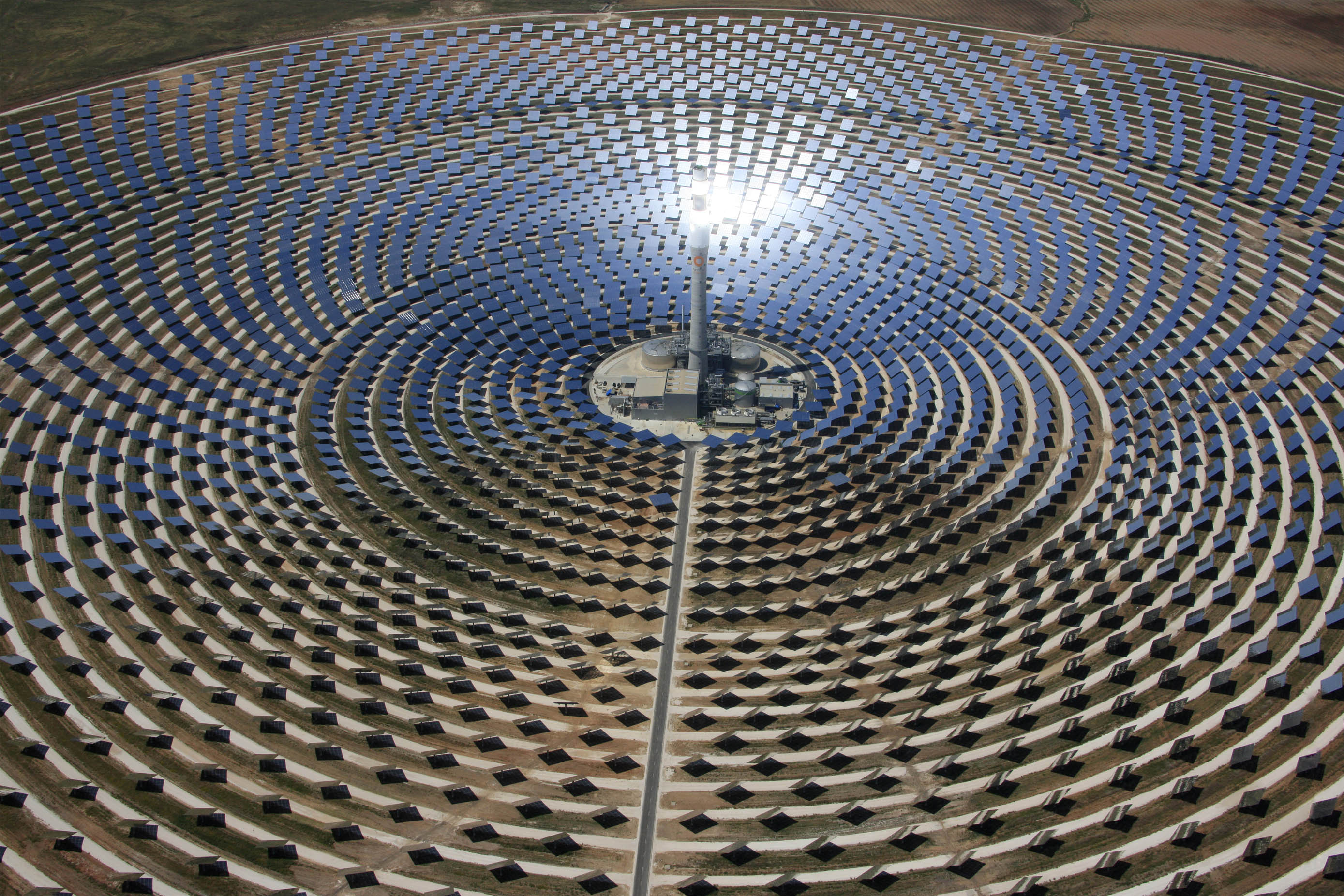
Another large scale application of this principle is used to generate electricity on solar thermal power plants where large fields of flat reflectors are oriented to concentrate the reflection on a point. Then water is heated to generate high-pressure steam and then run a turbine like in many power plants. A small scale use for this principle is also used to get hot water by running the water rough black pipes that are in the focus of a parabolic reflector.

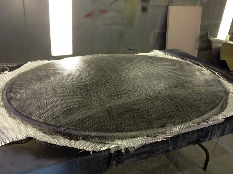
So lots of previous uses of the parabolic reflector but what's new in this project is the fabrication technique using burlap and epoxy for the reflector and the automation of the system, able to look for sounds itself.
What materials and components will be required?
-
Parabolic reflector
Burlap
Epoxi
Polystyrene
3D printed parts
Nuts and bolts
-
Electronics
Microcontroller
Microphone capsule
Preamp
PCB
Stepper motor
Connectors
Other passive components
Battery or AC adapter
Where will they come from?
I think this question should be split in two, where will they supply from? and where will they come from?
Burlap
Burlap is supplied from local stores, both textile suppliers and hardware stores with garden section sells this product. It is cheap and can be found in different colors though natural fiber color is brown. Burlap can be made from different vegetable fibers such as jute, hemp or sisal. Jute production is located in tropical areas (80% of production comes from India and Bangladesh) while sisal is native from Mexico but cultivated in other countries (most production comes from Brazil).
Epoxy
The epoxy resin is supplied from an online store in Madrid, and there are other online stores in Spain, but it is difficult to source it locally from stores. The supplier marks this product with his own brand (FeroCast) and it gives no further information of its origin.
PLA
The roll of PLA used for 3D printing is supplied from Amazon.es but its the PLA branded by bq. The origin its unknown but probably made in China.
Electronics
Electronic components are supplied from so many sources. Local stores supplied some electrolytic caps and connectors but they lack any SMD components and there are 3 electronic component shops in Gijón! So SMD components are supplied from eBay.es, Aliexpress.com, Farnell.es and some are supplied as samples from the manufacturers sample service. Electronic components come mostly from Asia, not just China but all over Asia: Japan, Taiwan, China, Thailand, Vietnam, Malaysia, Indonesia, Singapore. With minor production from Europe and the Middle-East countries.
Wow much will it cost?
The cost depends a lot on the quality of the components used, and where are they supplied from. A good microphone capsule like the one from Primo used for this build is 12€ plus shipping from the UK in my case, but cheaper capsules can be supplied from Chinese vendors for as low as 0.1€ each.
-
Parabolic reflector
Burlap 3.7 €/m^2 (1.5 square meters for 5.55€)
Epoxi 24€/Kg (350g used 8.4€)
Polystyrene 30mm thick 2.95€ per 800x1200
Polystyrene 40mm thick 3.95€ per 800x1200
First reflector cost: 20.8€
Each additional reflector: 13.9€ (as mold is reusable)
3D printed parts: PLA filament 20€/Kg (100g used 2€)
Nuts and bolts 2€ (est.)
-
Electronics
Microcontroller 3€ (est.)
Microphone capsule 12€
Preamp IC 7€
PCB 1.5€
Stepper motor 10-15€
Connectors 2€
Other passive components 3€
Battery or AC adapter 6€
Wire 1€
Total cost: 70.3€
What parts and systems will be made?
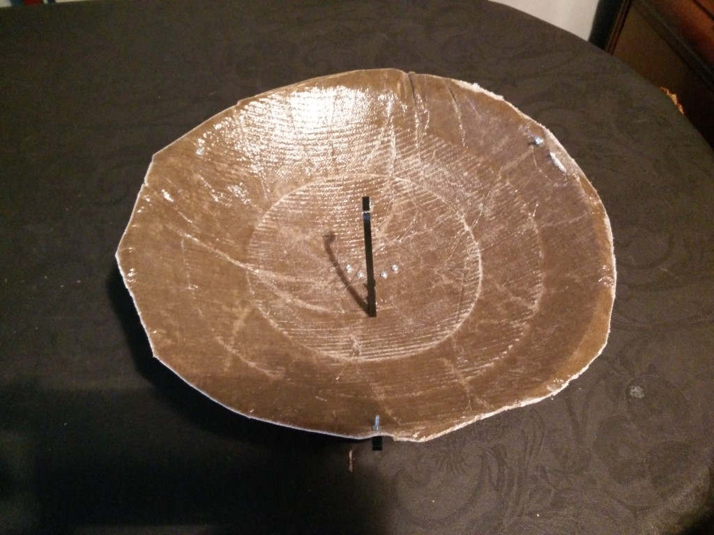
Parabolic reflector (composite)
The main part of the project is without a doubt the parabolic reflector. Not only because its fabrication is key to the success of the microphone, but because as I mentioned before, the parabolic surface can be used for multiple purposes by improving the composite process. For instance, to be used for radiofrequency, I want to test to insert a metal layer between the burlap layers, like some aluminum foil. Or getting a heat reflector by covering the parabola with mirror cardboard, or laser cut parts of acrylic mirror.

Electronics board for motor control and audio processing
I need a couple of things from the electronics. First, the output of the microphone should be pre-amplified so it can be used with a recording device. But in order to be able to detect sound sources for the second step of the project, I also need to sense the level of the signal to compare sound levels from different angles and pick the loudest. This has two different ways to go, I could make everything digital using a microcontroller or even a DSP, but that would require probably quite more debugging and for the sake of modularity it would be great to be able to use a reduced complexity system just without the sound tracking system, just with a little amplifier and headphones. If everything went through the microcontroller using the internal ADC or preferably an external ADC with 12-bit resolution (ATxmega series has 12-bit ADC, that would be nice). Once digitalized, the audio signal would be not altered if using it both to generate an output and to process the signal with some filtering and get the average level of the signal.
But I'm doing it analog, so a good input for the microcontroller would be the output of an envelope filter but in order to use the analog signal out of the microphone both for the envelope filter and amplification, I need to split the signal. This is something that might seem trivial, but when you add circuitry to a signal path, you can change the whole circuit and degrade the output of the signal. You can read about this in audio just by reading about "true bypass" on guitar effects. So a simple thing to do, that might not be the best, not for hi-fi audio but ok for the purpose of this prototype, is to use a voltage follower using an opamp. What this does is being a 1 unit gain amplifier, so it doesn't alter the level of the signal but the output of an op-amp has very high impedance, meaning that the circuit connected to the opamp out will see everything on the other side as if it was connected through a huuuuuge resistor allowing almost no electron flow from the output to the inputs.
Structure and rotation mechanism (3D print and/or laser cut)
As a consequence of using 3 thin burlap layers only for the parabola, the surface is a bit flimsy and deforms a bit. While I make a second version with more layers, I need this first version for testing. So I designed a printable structure based on the design made on SolidWorks, taking into account the thickness of the composite. Also, the rotation system will need some structure that could be made with 3D printed parts or laser cut parts. That is not decided yet.
What parts and systems won't be made
Bolts and nuts
Electronic components
Microphone capsule
For the microphone capsule I'm going to use an electret condenser capsule probably this Primo EM172 which I used before in an artistic project, and the artist pointed us toward this capsule which is farily priced (10GBP) and has a great sound.
What processes will be used?
Composites
3D printing
Electronics design with input and output devices
Programming
3D modeling
2D modeling
What tasks need to be completed?
Mill the parabolic surface on polystyrene to make the mold
Composite process with burlap and epoxi
Print the parabolic holder parts
Print the mic capsule holder
Make the PCB
Solder components on PCB
Program the uC
Wire the microphone to the PCB
Print or laser cut the parts for the mechanism
Assembly the mechanism
Sound testing
Mechanism testing
Sound-searching testing
Document the process
Make the video
Make the slide
Tasks to complete in the next weeks are:
Design the PCB
Make the PCB
Solder components on PCB
Program the uC
Wire the microphone to the PCB
Print or laser cut the parts for the mechanism
Assembly the mechanism
Sound testing
Mechanism testing
Sound-searching testing
Document the process
Make the video
Make the slide
Since I've already made the parabolic reflector out of burlap epoxi composite on week 14. I have to focus now on electronics and testing mainly. I'll begin by just testing some simple audio output and hearing it to get a grasp on how directional the microphone is and sensitive to distant sounds.
What questions need to be answered?
Does the actual parabolic surface concentrate the sound?
How much the irregularities of the milling affects the reflection?
What is the schedule?
I'm presenting 20th of June so I have 3 full weeks counting from 30th of May
Week 1: Electronics design, documentation Schematic design PCB design Sketch the whole system
Week 2: Structure design and fabrication, documentation
Week 3: Programming, testing, video and slide, final documentation
How will it be evaluated?
The success of the project will rely on two main aspects. The first is whether the directional microphone works as intended. Meaning that it is capable of recording distant sounds clear. For testing this performance I'll place the Soundflower in an environment with different sound sources and place my own source probably with a speaker and try to record it starting close and increasing the distance of the source.
Then comes the automation sound tracking, for that I will place the microphone in different environments and test the behaviour of the programming to locate the loudest sound source. First, I will test it in a low noise environment where I can place my own source. Then choose some environment with different sound sources and check the behaviour again.