Week 15: Networking and communications
For this week I've chosen the nRF24 module to do the assignment. And as there is a convenient library for Arduino, I'm also trying to program the ATtiny44 using Arduino.
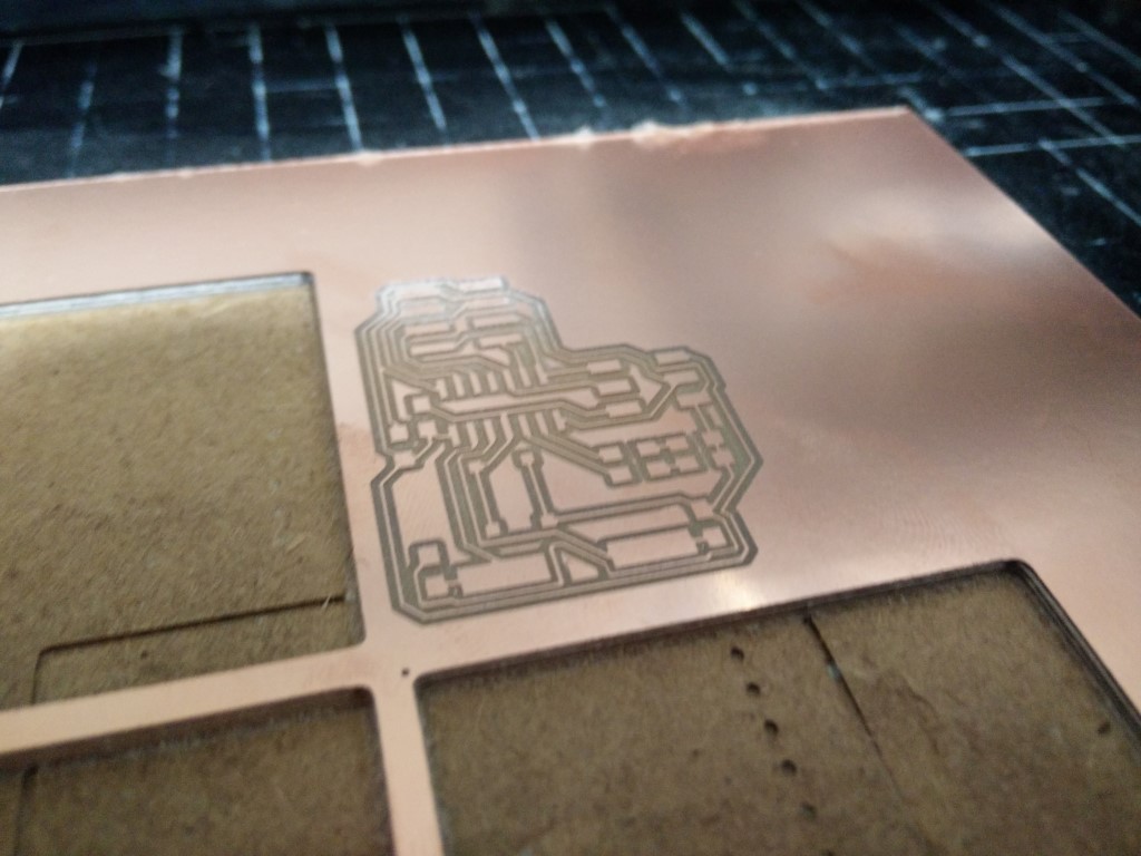
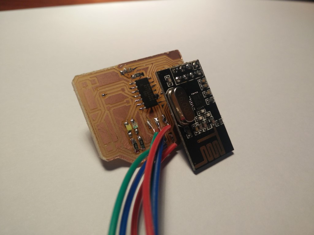
The design of this board is very simple, I've just added a couple of LEDs and a button with the extra pins to be able to have simple input and outputs for testing. Still loving KiCad, smoother everytime. But I've made a couple of mistakes. First as I didn't have a proper PCB layout for the nRF24 module. It overlaps with the ISP pins, so I've soldered some jumper cables to program it. That wouldn't had happened if I went through the process of 3D simulate everything. Another issue is that I miss connected SCK pin on the schematic! And it could have been worse, but SCK on the ATtiny was attached to nRF's IRQ which is not necessarily needed. It would allow interrupting the µC when data is received instead of polling the nRF on every loop, but for this weeks purposes, I just fixed the board, by cutting the trace from SCK on the µC to IRQ on nRF, and soldered pin 9 and 10 on the ATtiny by adding a solder blob. I've fixed this later on the KiCad project, so files listed here under downloads are right. Bitmaps for milling the traces and outline are wrong, that what was fabricated.
I've discovered this while trying to program the board and I got "double check connections".


Another thing was that I thought that I had female SMD 2x pin headers but not, and had to do an SMD conversion to the module. First, I bent the pins to get them to the same height, then removed the pins from the module using hot air, then trimmed the pins and soldered them to the board to finally re-solder the module board to the pin header now attached to my board.
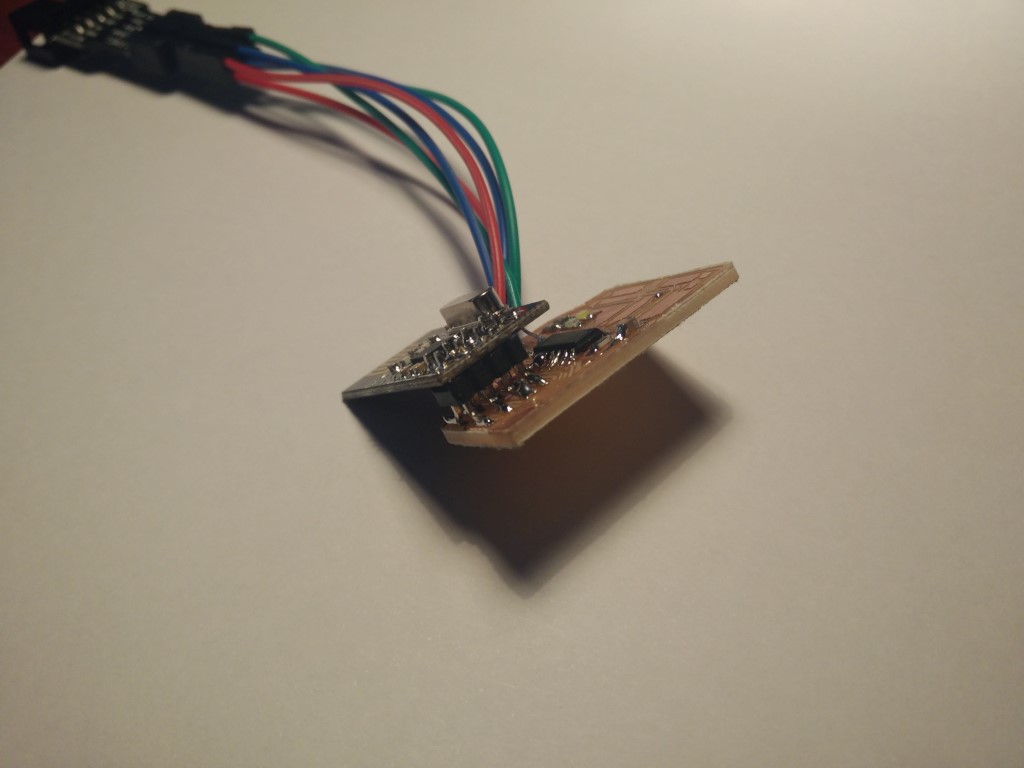
Now it's time to solder the other board and start testing with both of them.
I've soldered everything and started programming. This time, I wanted to try Arduino IDE for the ATtiny, also because I've used the RF24 library before and it's pretty useful. I've modified the "GettingStartedRF" example and changed serial messages to led blinking on board. Everything programmed right, but it's not working, probably because I supplied 5V to one of the modules, that are 5V tolerant meaning that you can use 5V signals on input pins, but not on the supply voltage, so I probably fried them. Now I'm waiting to get another couple and test them.
I've got this assignment pending and last weeks I've been more bussy with the final project, so after presenting it is time to get the nRF24 modules working. I've checked the first couple of modules with a couple of Arduinos and they are just fine. Those modules were supplied 5V for a short period so it is not so risky to feed 5V to the nRF24.
I've used nRF24 modules previously with Arduino using the RF24 library but never with an ATtiny. I only have a couple of LEDs for debugging the code and I've should have included a ftdi header to enable serial communication. That could have saved me lots of time!
So I started using the GettingStarted.ino sketch from that library modifying it for my board. It is important to notice that I'm working with Arduino IDE 1.6.9 and to use the ATtiny I just had to go to Tools > Boards > Board Manager... then search ATtiny and it will show ATtiny by David A. Mellis (who by the way is one of the founders of the Arduino). But if you go to find examples of people using ATtinyx4 with nRF24 you'll find that most people are using another core for the ATtiny for the Arduino from someone nicknamed "Coding-Badly" (hehe) both at Google Code and GitHub. Installing the cores for other boards or processors is quite different from older versions of the Arduino IDE to the new one, at least on Windows. It used to be on the "hardware" folder, either at the installation path (e.g. C:\Program Files\Arduino\hardware) of the sketchbook path (%SKETCHBOOK_PATH%\hardware) same as with libraries. But now, for the Arduino IDE to read other hardware (and I've just told you how easy is to get one from the board manager) it needs to be in the AppData folder on the user folder, something like C:\Users\Luis\AppData\Local\Arduino15\packages and that would be the new "hardware" folder. From what I've read that has to be with the way Windows shares files on networked computers running a central application. Being in the AppData folder allows to refresh those files while running.
I wasn't getting any writes or readings from the modules, by looking what parts of code where reached trough the led-debugging. So I've started to search for specific uses of the nRF24 modules with ATtinyx4 and ATtinyx5 processors. That's when I found this great post that explains that the tinys don't have hardware SPI pins but USI, that can be configured either as SPI or I2C buses. And since that doesn't behave exactly as SPI, the SPI library that Arduino uses wouldn't work with that. Ok, I'll get an SPI library for the tinys, in fact, this nice project combines a couple of interesting libraries and the hardware cores. Because it wouldn't be just enough to change the SPI library but to change calls to that library made by the previously mentioned RF24 library.
For a start I just want to send a value from my nRF24 board to an Arduino using another module displaying it using the serial monitor. But I didn't get it to work, so I started to get deeper and read about channels, addresses, RF power flags... learned a lot, but everything was ok. I was using the Mirf85 and SPI85 libraries on my board and the RF24 on the Arduino Uno but I didn't get it to work. On the way, the most important thing is to have the correct numbers for the pins. That meaning that from one hardware definition to another the same pin may have different numbers (aaand it does). And the CE (chip enable, used to save energy) and CSN (chips select, aka slave select, n stands for negative as it is of inverted polarity, ground to select) pins can be configured to be any digital pin, but SPI pins are not. In the tiny44:
physical pin 1 - VCC
physical pin 2 - - PB0 - Coding Badly core pin 0 - Mellis core pin 10
physical pin 3 - - PB1 - Coding Badly core pin 1 - Mellis core pin 9
physical pin 4 - RST - PB3 -
physical pin 5 - Blue LED - PB2 - Coding Badly core pin 2 - Mellis core pin 8
physical pin 6 - Red LED - PA7 - Coding Badly core pin 3 - Mellis core pin 7
physical pin 7 - MOSI/DI - PA6 - Coding Badly core pin 4 - Mellis core pin 6
physical pin 8 - MISO/DO - PA5 - Coding Badly core pin 5 - Mellis core pin 5
physical pin 9 - SCK/USCK - PA4 - Coding Badly core pin 6 - Mellis core pin 4
physical pin 10 - - PA3 - Coding Badly core pin 7 - Mellis core pin 3
physical pin 11 - - PA2 - Coding Badly core pin 8 - Mellis core pin 2
physical pin 12 - CS (mine) - PA1 - Coding Badly core pin 9 - Mellis core pin 1
physical pin 13 - CE (mine) - AREF - Coding Badly core pin 10 - Mellis core pin 0
physical pin 14 - GND
Basically one is clockwise and the other one counter-clockwise to number the pins. So I checked I had the correct numbering by checking the led's outputs. While looking for solutions I've found another RF24 library that supports ATtinyx5/ATtinyx4!!! and even had an example to serve as a transmitter for the GettinStarted.ino example. The only thing to modify was the pinout as this was based on the "Coding Badly" core definition. I've included the modified version here to download. This library, starting by the RF24.h, includes RF24_config.h, in which is defined that if __AVR_ATtiny44__ is defined (or a bunch of other tinys) it would call utility/ATTiny/RF24_arch_config.h that finally includes "SPI.h" (notice the double quotation for a header that it's in the same directory, not taking the global SPI library header for Arduino). And it includes this comment:
// Include the header file for SPI functions ( Main SPI code is contained in RF24.cpp for simplicity )
So back to RF24.cpp, at the very bottom of the file, there are some pin assignments for DI, DO, USCK, and SS depending and are different for different tiny micros. Anyway I had to change the definition for the ATtiny44 as the pin numbers are different
With everything changed, everything compiled, and should be working, but no, I still wasn't able to receive anything from my board. After double checking everything I noticed a "classic" mistake, that is to hook up MISO with MISO and MOSI with MOSI and in the case of the RF24, they should be crossed. So you can imagine my face after realizing that. Well, I don't know now if I'll be able to go to León to mill some new PCBs (the KiCad project linked below is already corrected). But for now I just used some dupont cables just to check that it works, but on the pin header I've used (trough hole converted to SMD) the pins are too short and when there is some movement it disconnects and stops sending data properly.
So what the program does is very simple, it just increments and sends a counter, that the other board can read and show trough serial. This is a good example of how programming is not only about the lines of code, and the design of your program but also about fiddling with dependencies, compatibilities and so.
Finally I wanted to do something between the boards, I should have put more buttons and leads for external sensors, but with what I have now, a thing I can do is to still send an incremental counter and have the other board react. So in the same sketch I defined a variable for radioNumber (0 or 1). So radio number 1 is sending a counter every second, but after sending it, it listens for the counter to come back if it is the same it will blink the blue led. On the other side, radio number 0, is listening and if it gets a package that divides exactly by 10, it lights the blue LED until next package is received. So basically if everything goes well, board 1 will blink every second and board 0 will blink every 10 seconds.
Machines and software used
SO: Windows 10, Ubuntu 12.04KiCad
Roland Modela vPanel
Arduino IDE
Roland Modela MDX20
0.4mm PCB routing mill (traces)
0.8mm PCB routing mill (outline)
Files
Modified RF24 library to work with ATtinyx4 and Mellis coreArduino Sketch to load on an Arduino
Arduino Sketch to load on custom board and send to an Arduino Uno
Arduino sketch communicating the 2 custom boards
Kicad Project
PCB traces
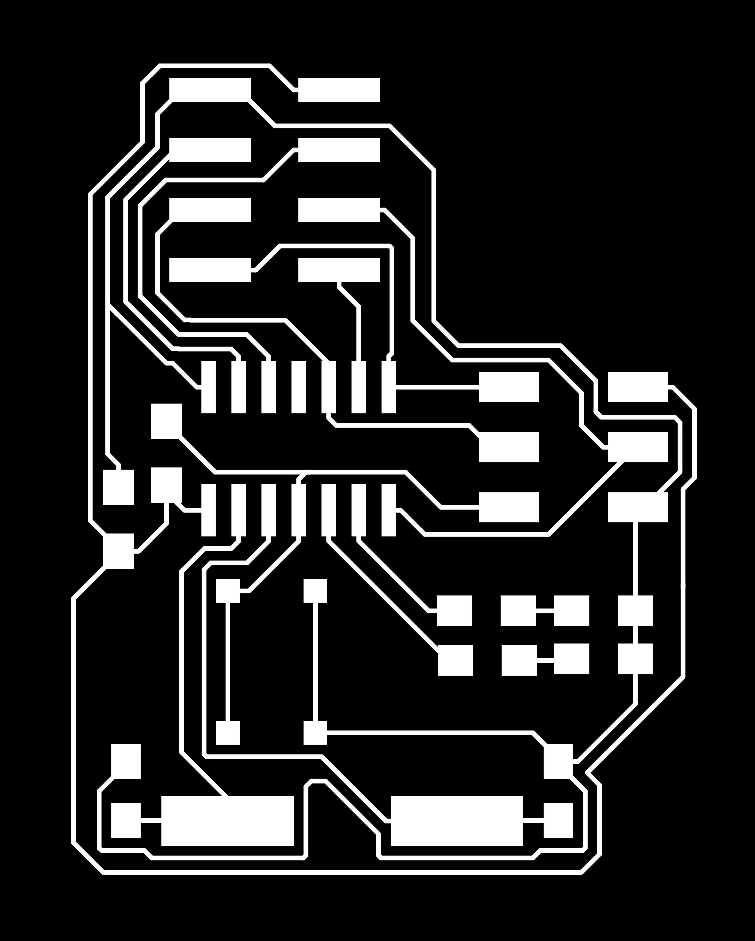
PCB cutout