Week 3: Computer-controlled cutting
Ok, first of all, I need to improve a little bit the week 2 page, because I realized on project reviews this Wednesday that a good thing is that I wrote the process a little bit but just put images of the results, of the renders, and only for 2D and 3D not for pixels.
Vinyl cutting
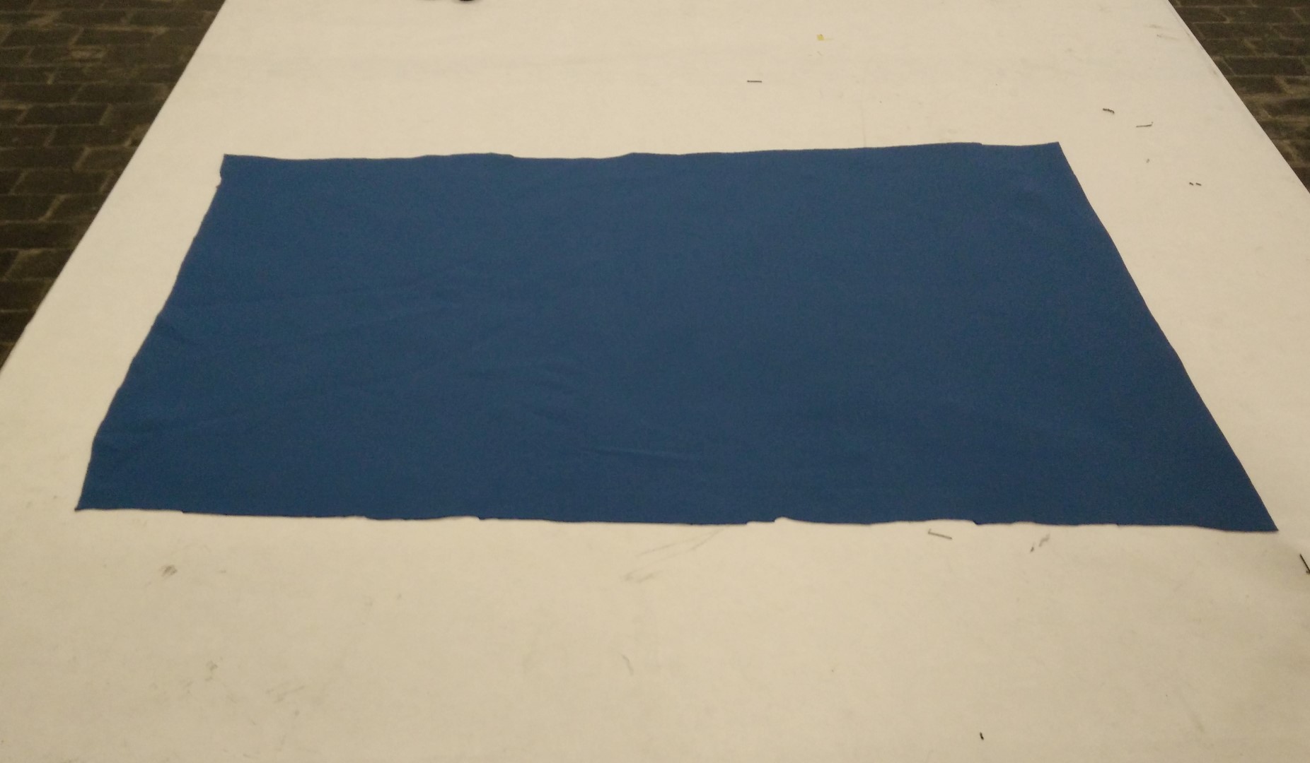
Then I'm going to start showing something I've made with the laser cutter and textile vinyl. I wanted to do something I've learned when Anastasia Pistofidou from Fab Lab Barcelona was here at LABoral during last winterLAB. I was assisting her with our laser cutter on her workshop about wearables. In the workshop, she used this "fake neoprene" textile that works great on the laser cutter. True neoprene has chlorine so it's a big no for a CO2 laser cutter.
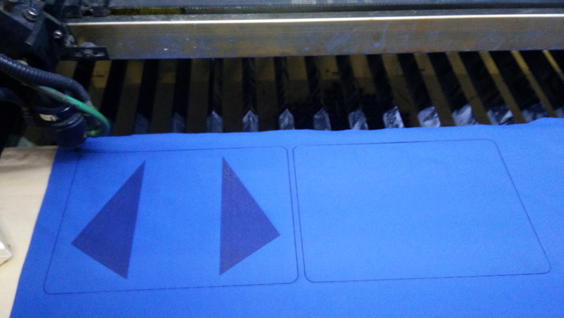
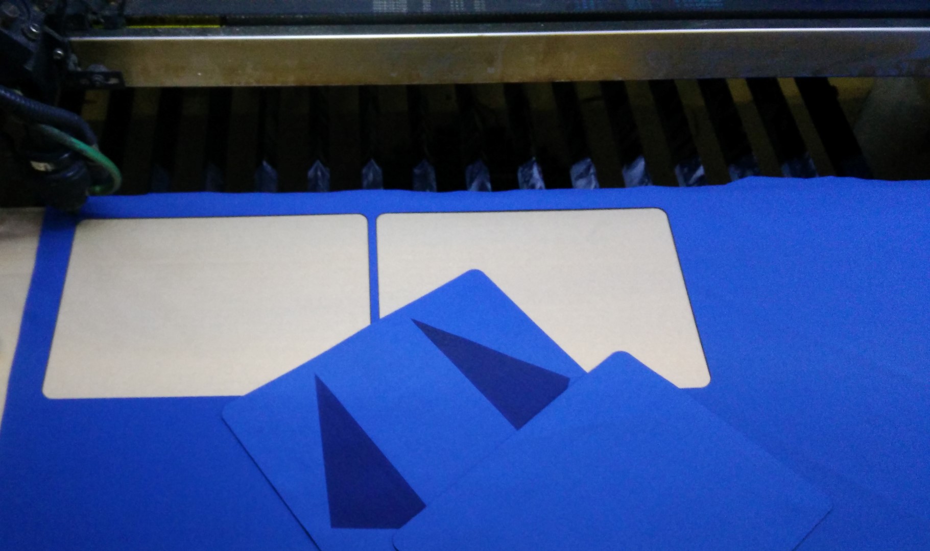
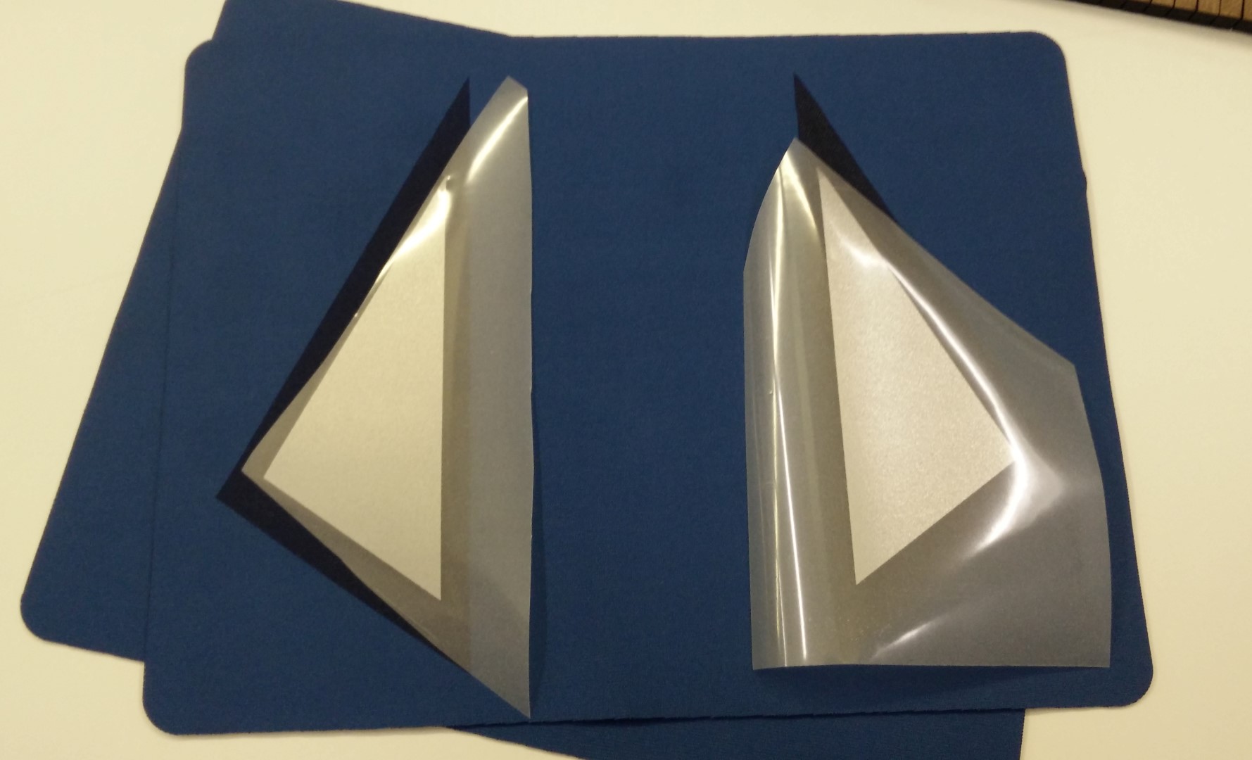
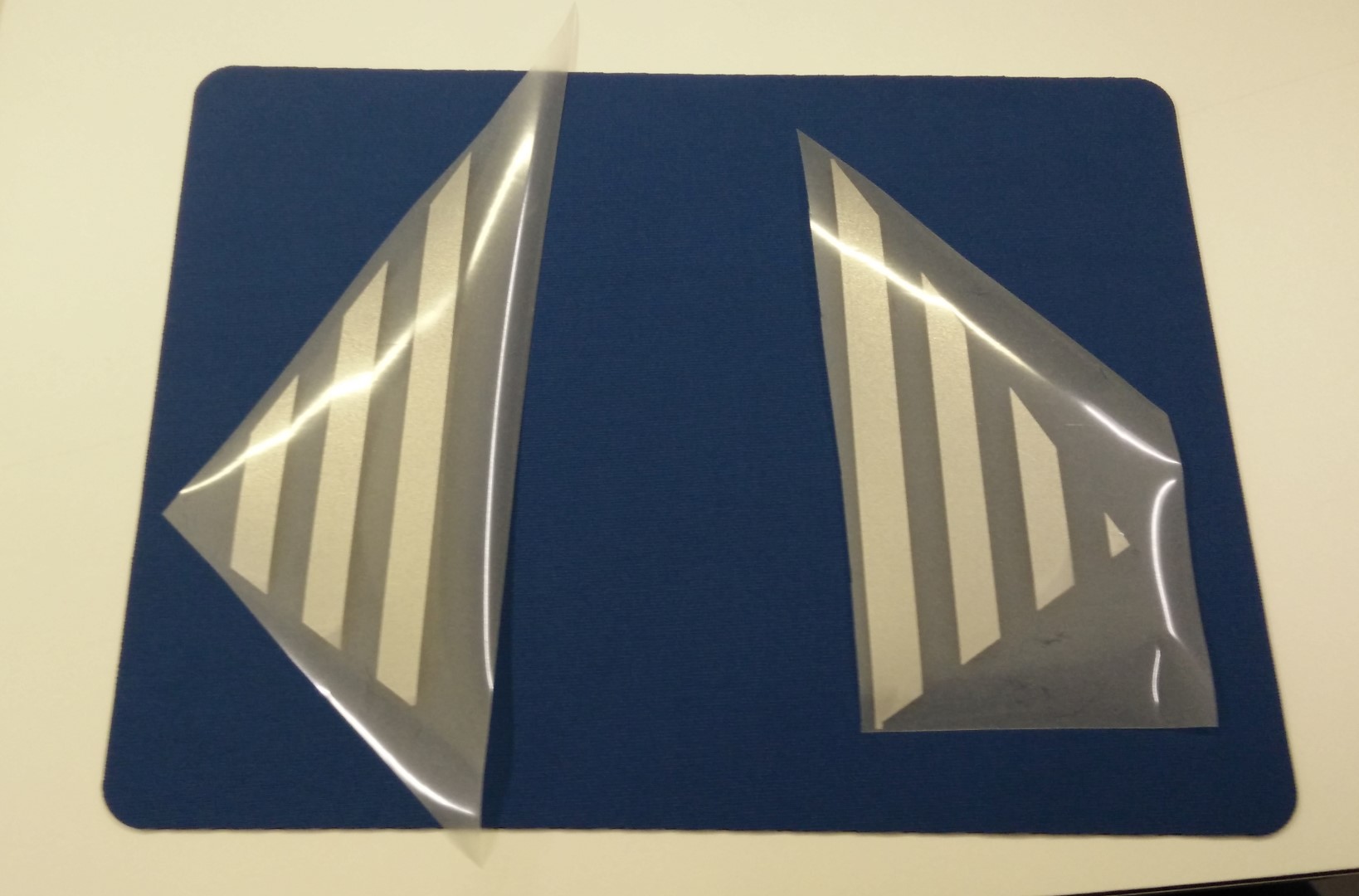
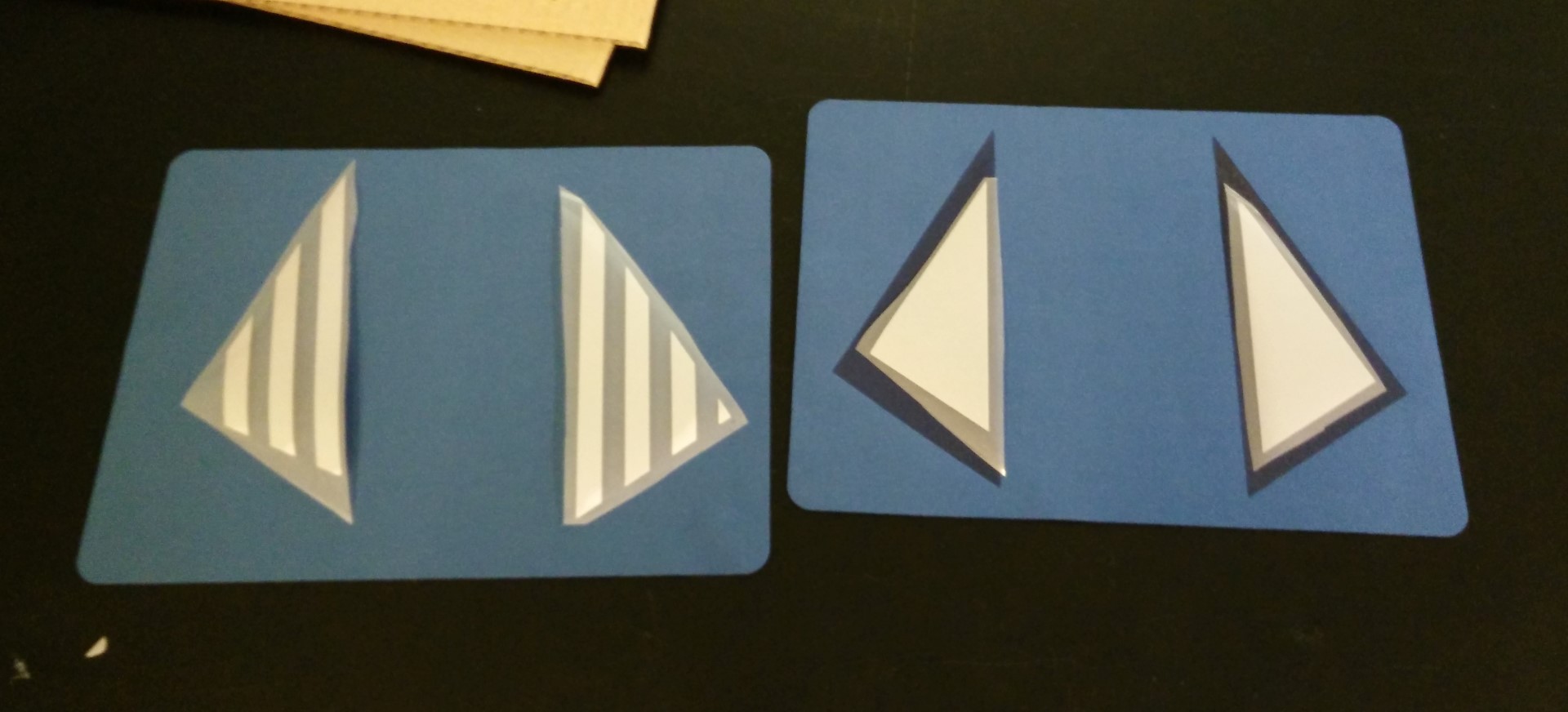
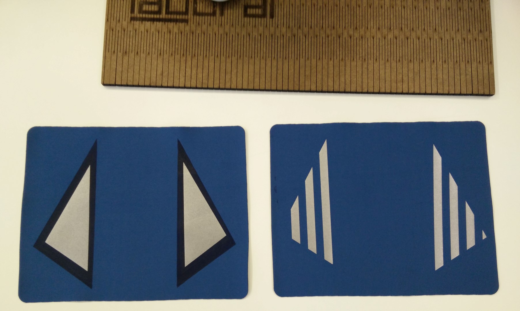
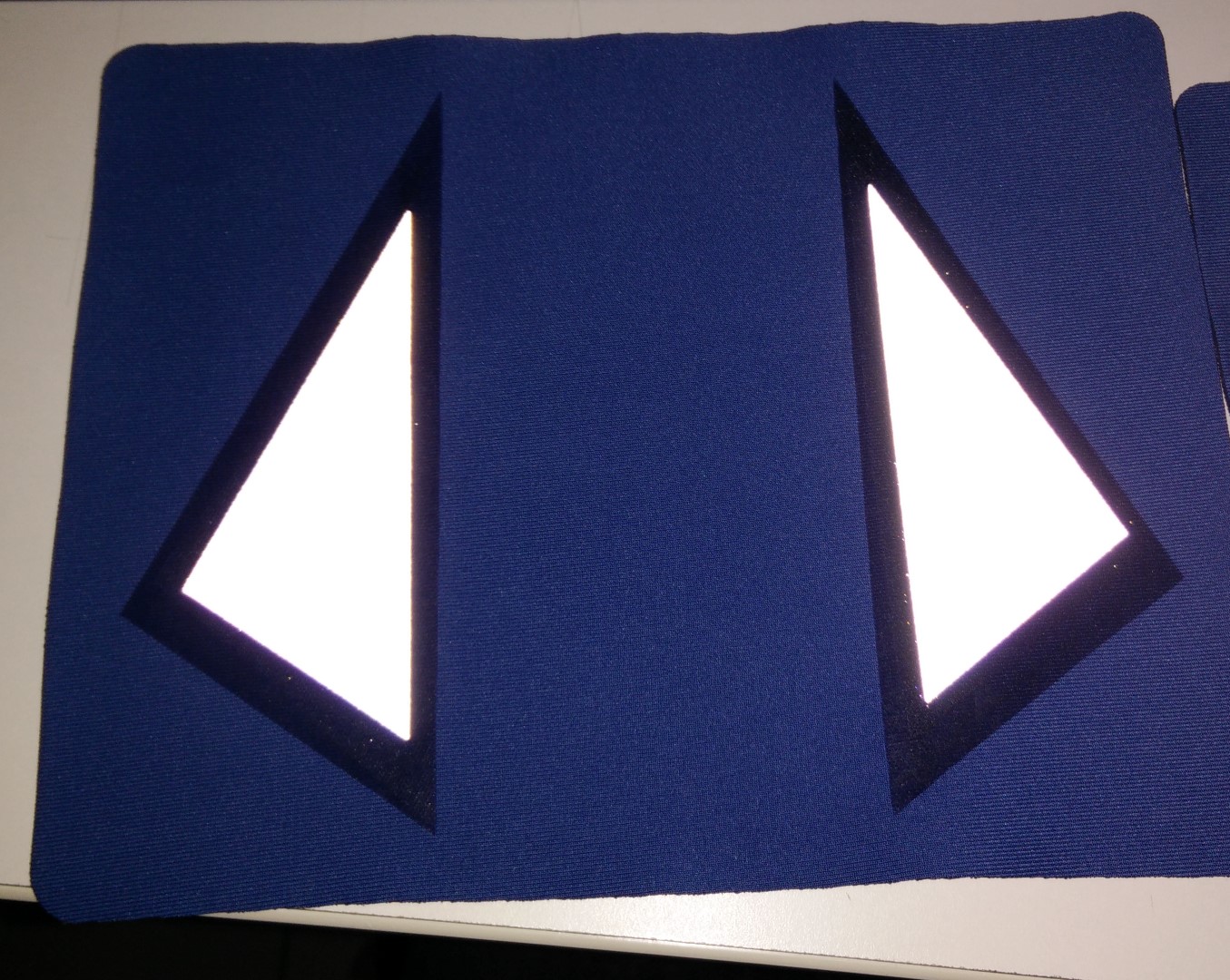
I wanted to test a couple of things. So first I made a simple design for the laser. It had two parts to cut, one with a couple of triangles engraved, it burns the surface nicely leaving this darker colour and also a different texture. So later I could test the reflective vinyl on both engraved and plain textile. I've also made two vinyl designs, one stripped and the other one solid, so I could feel how the material peeled.
I have to confess that I didn't check the cutter plotter force before sending the design and it lacked a bit of force. It was set at 100gf and the manufacturer specifications are 120gf. Anyway I was able to cut it but it wasn't as easy as with other textile vinyl and I've missed a tiny triangle.
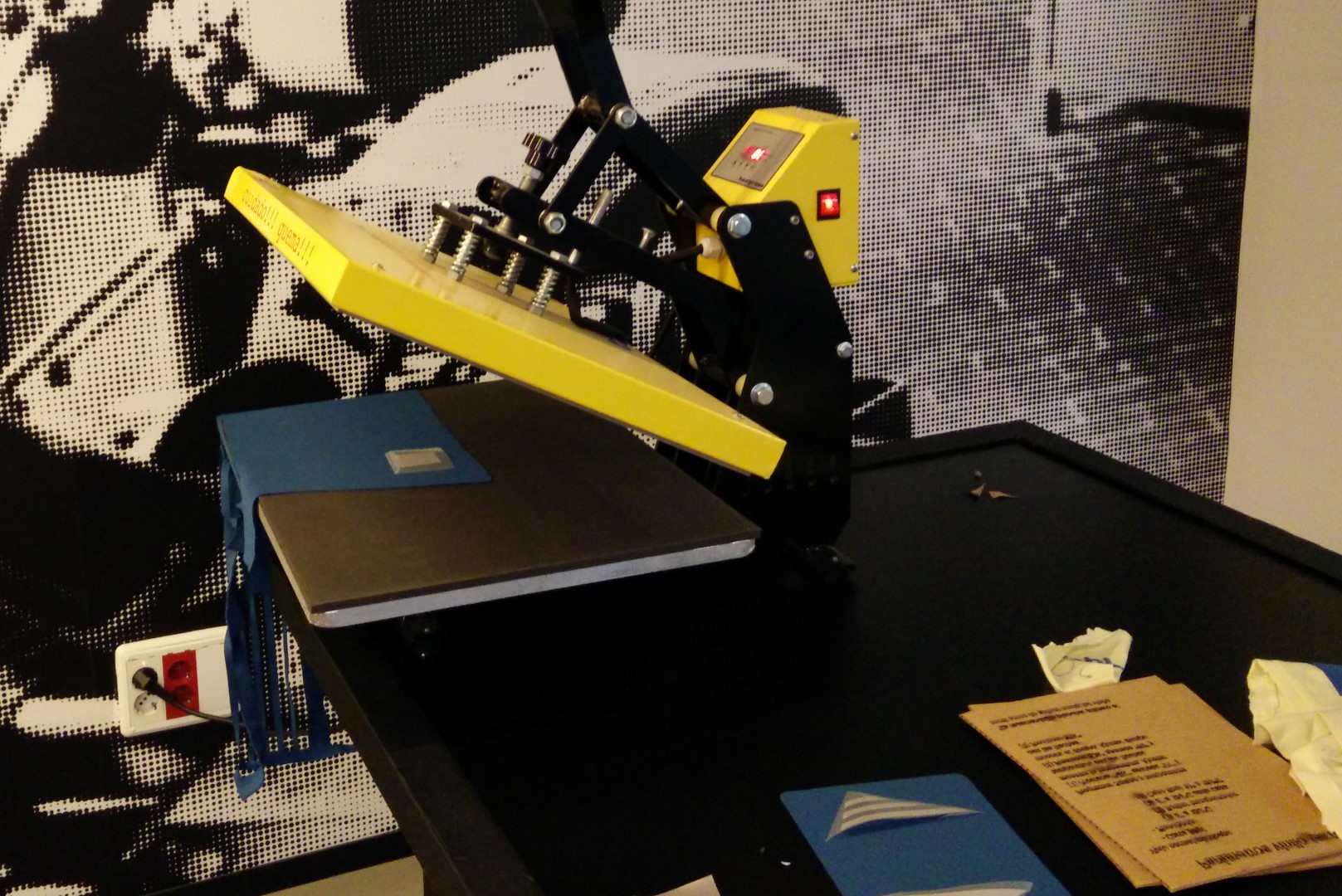
I've found that on this kind of textile, may need less time when applying heat on the seconds step once the support is removed cold. It indicates 10'' and on the first test, after 10'' the textile melted a little bit and there's residue on the Teflon sheet I'm using (not silicon paper). So for the next one, I just went for 6" and it feels nicely stick to the neoprene
Another interesting technique shown in the pictures is using a piece of cardboard slightly moistured with a water spray to help get the textile plain and stick to a flat surface.
For using the vinyl cutter I can use InkCut for Inkscape (Linux only plugin) or use Roland's software CutStudio. I'm starting to use fabmodules but for this week's assignment I've used InkCut.
Using InkCut is quite simple but you have to learn a couple of tricks. Basically, first, you have to import what you want on Inkscape. Fortunately, Inkscape admits a lot of formats but you may need to test a little bit to get the correct output format. In my case I usually draw this more "non-technical" things with Inkscape itself, but when sometimes I need to get a drawing out of DraftSight I know that 2012 ASCII .dxf formats works perfectly (and with other machines and software I'm using too). Once you have every vector imported in Inkscape, it is time to ungroup everything (Ctrl+Shift+G) and make a path out of every object by applying "Object to path" (Ctrl+Shift+C). Then remember to select all the vectors you want to output to the cutter, you can have more on the document and will be ignored if not selected after next step. To get into the plugin click on the extensions menu and then InkCut. I don't have any screenshots because I'm so used to it and it's like printing some documents! that I didn't consider screen shooting that, sorry. But basically at this point, if the drivers are correct, it should show you the path preview and you can open the preview itself as an Inkscape document. Once happy just click "Send path" and enjoy. One last thing, this didn't occurred me this time but like half a year ago. If you're experiencing weird scale problems with Inkcut, check your document properties (Ctrl+Shift+D) and make sure that the document units are the same you expect the machine to be configured to, in my case mm. Because it usually is set to pixels and that may cause scaling problems.
They are super simple drawings, but for the sake of docummentation here are the files:
testVinylLaser (dxf)
testVinylLaser (svg)
vinylTriangles (dxf)
vinylTriangles (dwg)


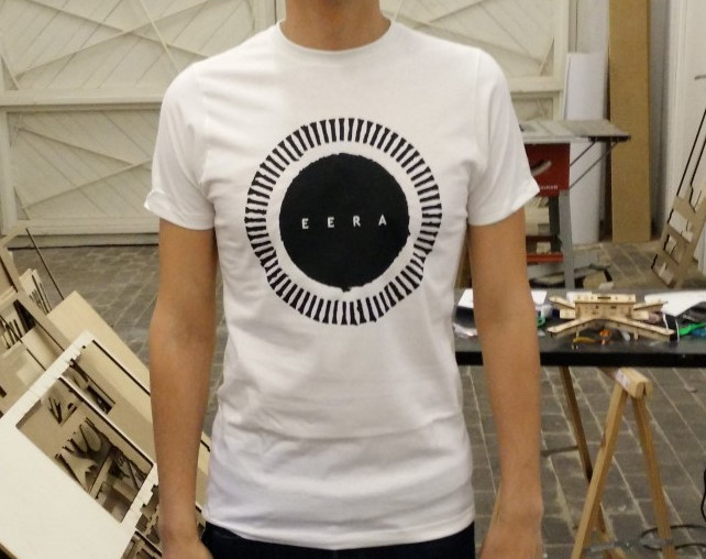
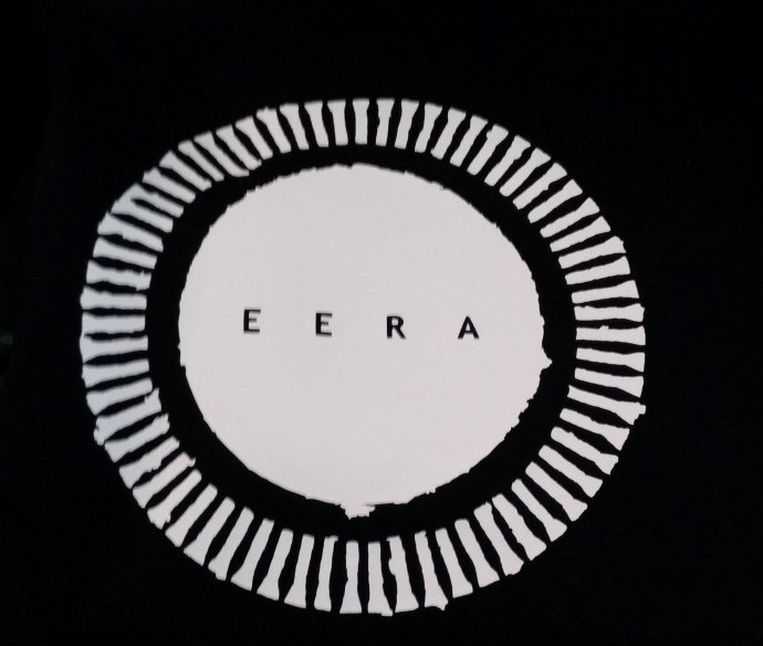
Another thing I've made with textile vinyl were prototypes of t-shirts. I play in a band and the drummer is a graphic designer so we tried some designs with vinyl.
One of the things that I've found having a vinyl cutter is that it works great for introducing kids to the Fab Lab because they can see how quickly they can transform a computer drawing to a sticker. We had a workshop making foamboard planes and for the last part they made custom stickers, they loved it!

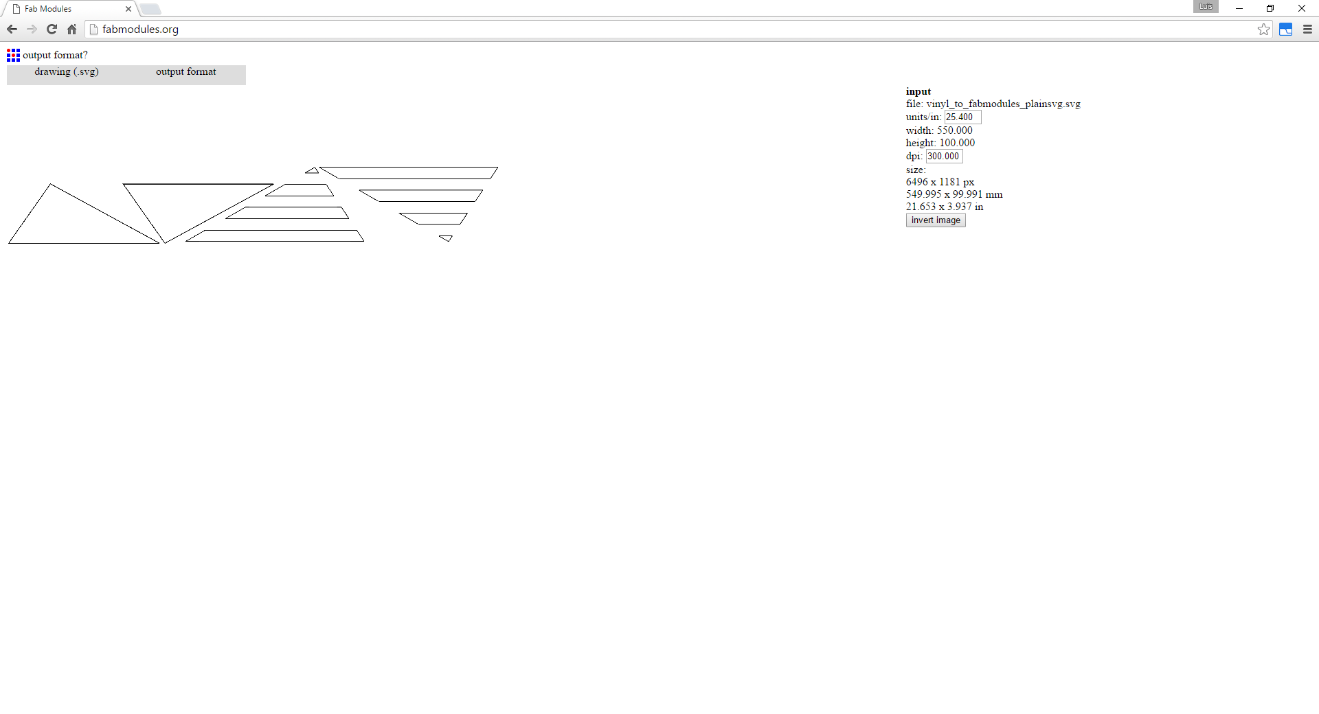
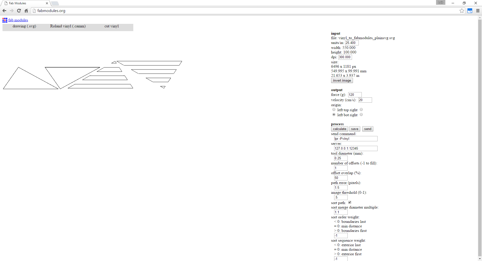
Update: After using fabmodules.org for a while for PCBs I wanted to try it for other processes other than PCB milling. So I've included here the workflow for getting a .camm file from a .svg.
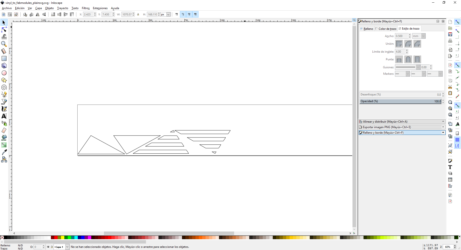
The first thing is to get the design I want to cut as a svg. Depending on the origin of the design that would involve making some conversions. With Inkscape svg is the standard format for saving files so that would be enough. I just had a bit trouble with the path until I realized that it was having a tool width so I increased the thickness of the stroke in the design until fabmodules.org got the path right. Seems that it needs the stroke to double the tool thickness so using the default .25mm thicknes for the blade, a stroke of .5mm did the job. Once the file is correctly imported on fabmodules, it is just a matter of getting the right force and speed parameters.


Laser cutter
So now it's time for the press-fitting kit. The cardboard available at the fabLAB it's not the good one. Another option I have available is foamboard, but the foam retracts so much due to the heat that exposes the cardboard edges and they cut quite a bit so it's not very nice to handle.
I've done some stuff with press-fit with finger edge joints, but always conservatively about the press-fitting knowing that in the end will use some adhesive. I use MakerCase.com a lot for press-fitting cases. It even lets you put your machine kerf and will take that into calculations.
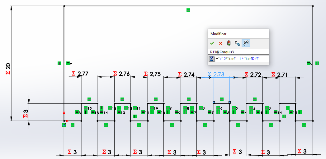
First design is a parametric kerf test for SolidWorks. It has seven different slots which size is a result of the thickness of the material e, the kerf value is taken from the previous measure, and a diff parameter that determines how much the slots will vary from the kerf measure. The center slot has just kerf removed and should be the right one, but depending on the material's elasticity, sometimes a tighter o looser fit is better.
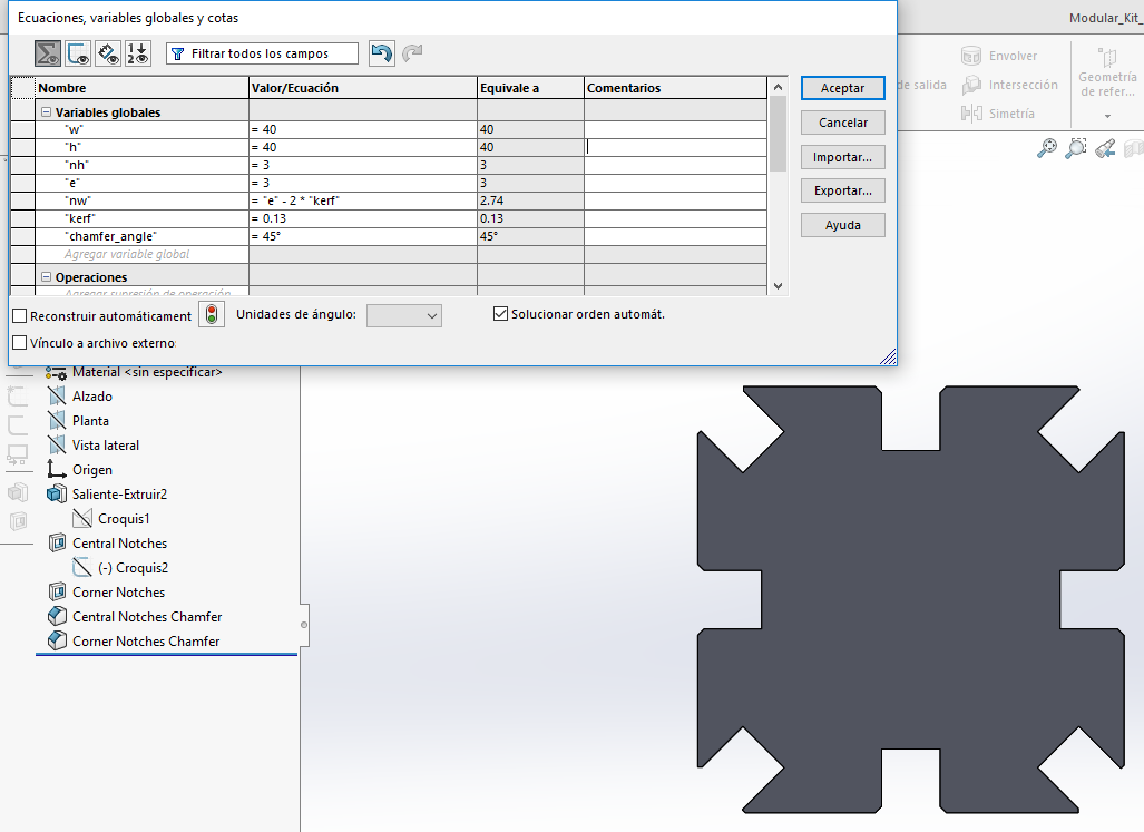
Using variables is easy in SolidWorks, for just global variables, just enter a measure_name when entering a measure, it will ask if you want to create a global variable with that name and you give it a value. From now own you can refer to that value as "measure_name" and use it in equations. For entering an equation you must first write equal sign.

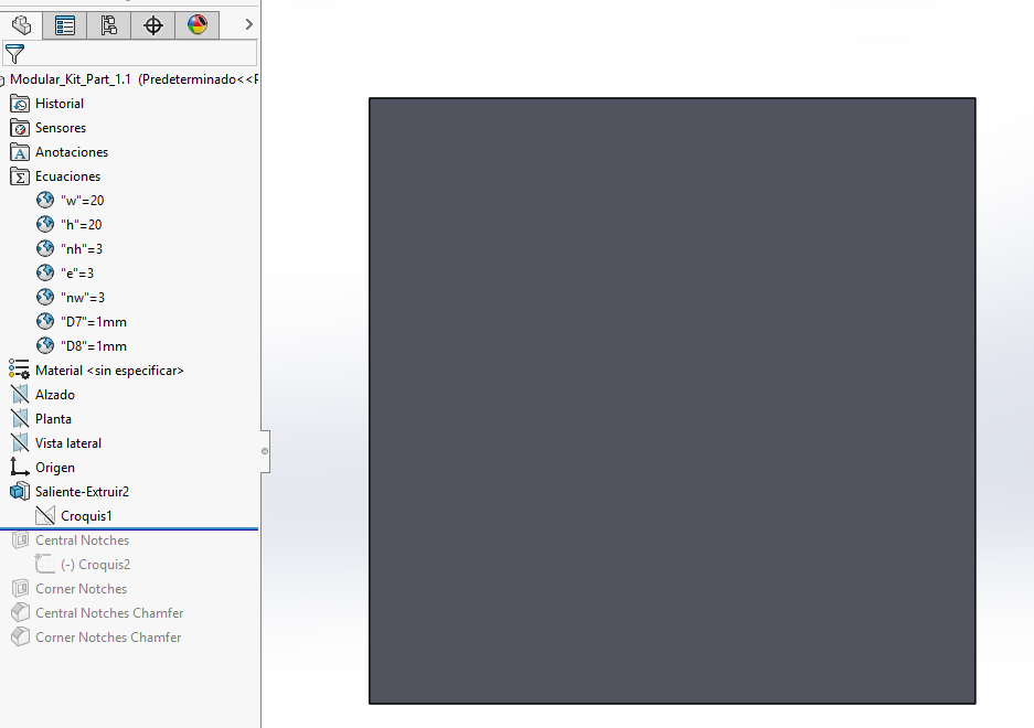
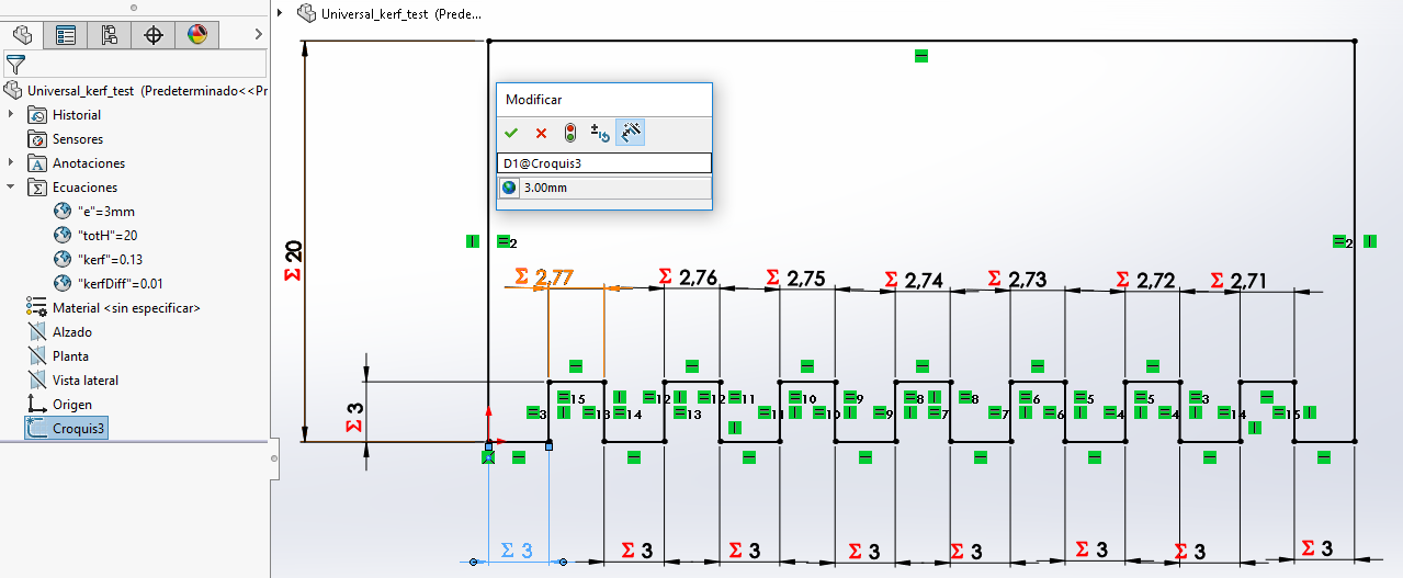 View with the global variables
From SolidWorks I can export as .dxf for the laser. Files:
Universal_kerf_test (.sldprt)
Universal_kerf_test (.dxf)
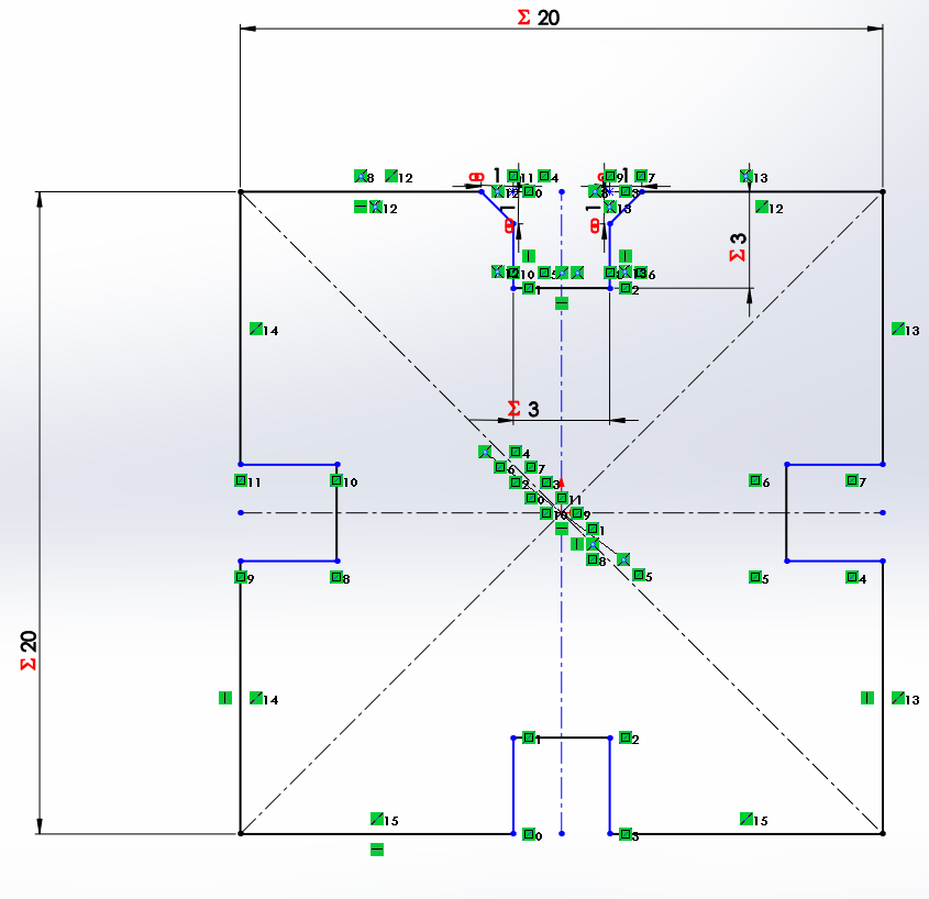
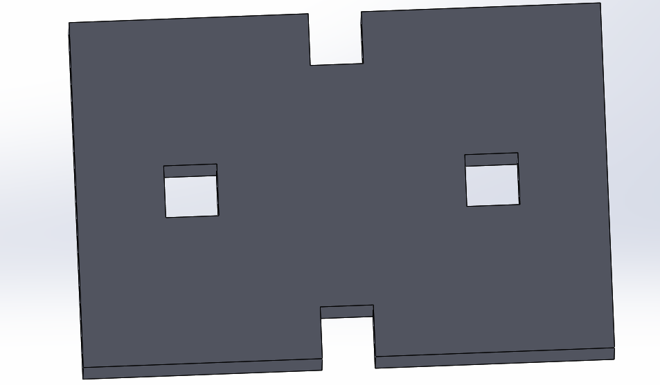
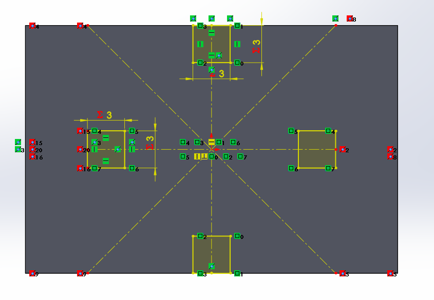
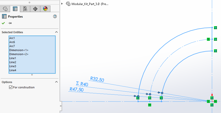
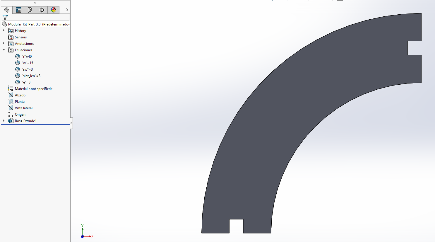
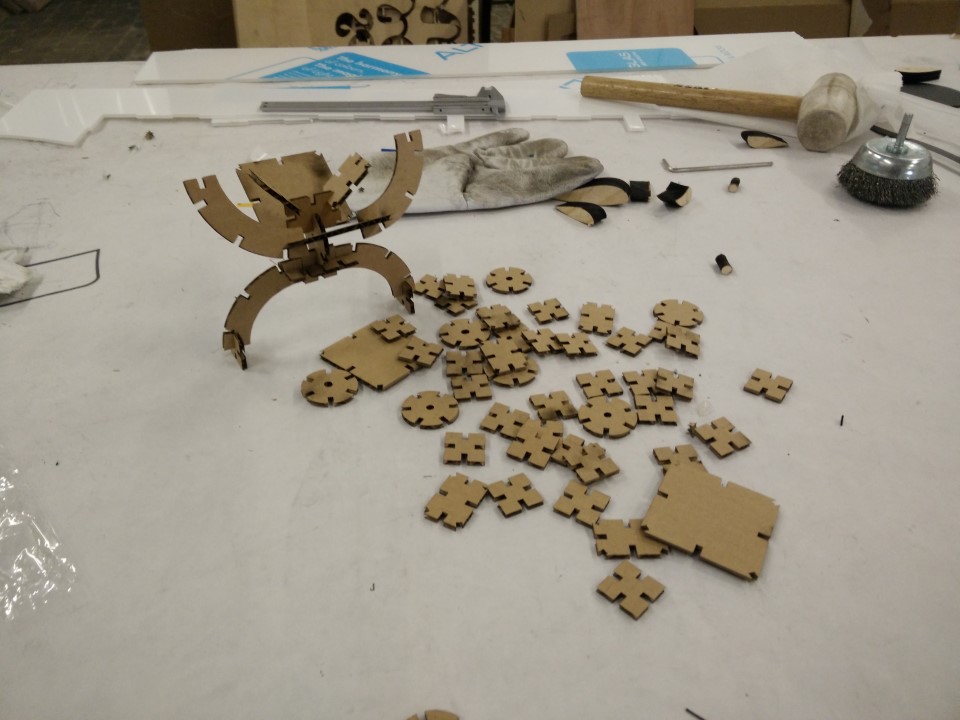
And now the press-fitting kit. I made some GIK like parts using parametric design in SolidWorks. So, with just a file, the most different parts could be created not only in terms of sizes but in terms of features. So I've started just with a basic square/rectangle. The first thing I've realised was that trying to parametrize chamfer dimensions on the sketch was going to be quite more tedious than as a volume. So even though I supposed that I was going to use just 2D (and went for the part instead of the drawing because I kinda prefer the interface) I've ended up using 3D features to then export just one face to the laser cutter.
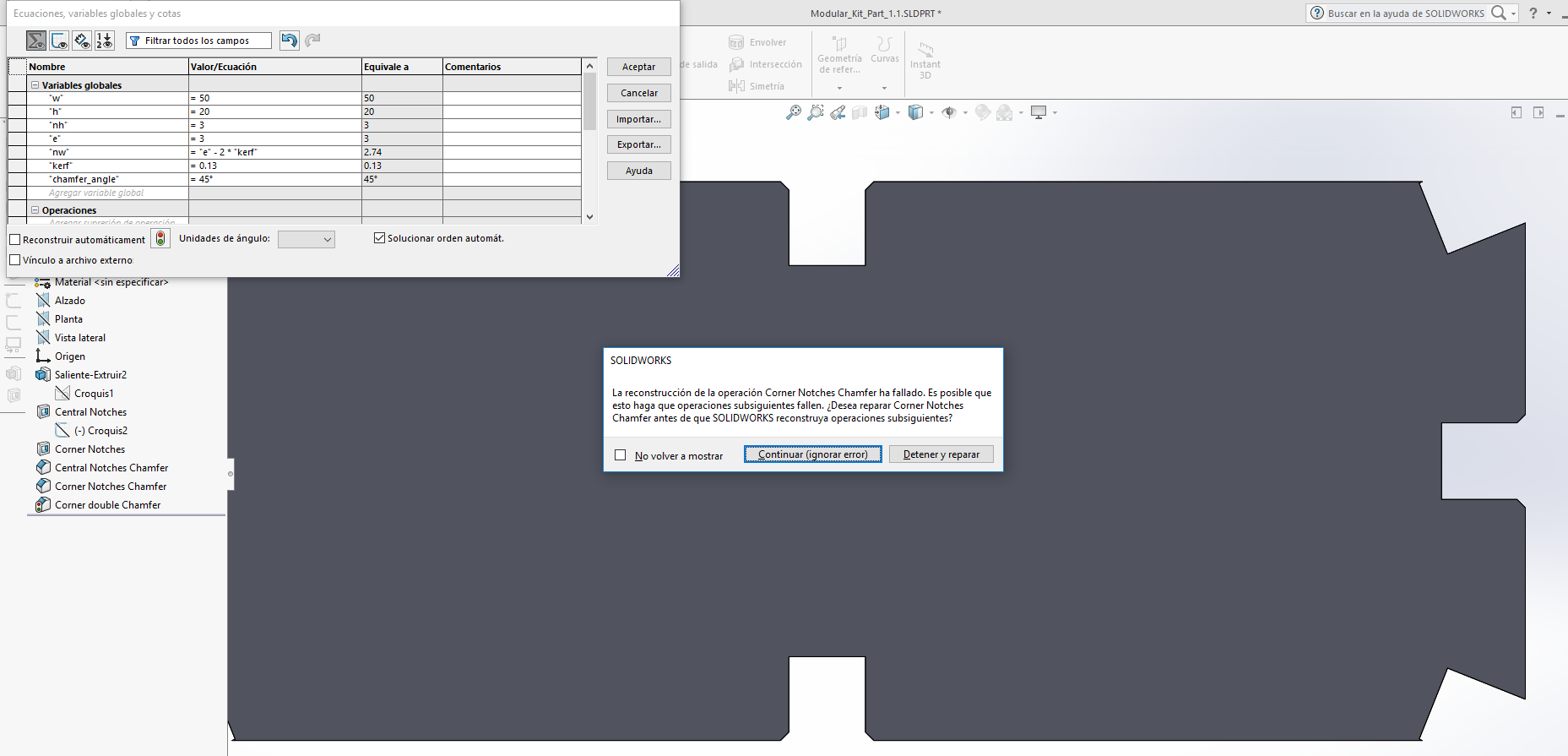
Another interesting moment in SolidWorks is fixing sketches. From what I've learned, it is crucial to control relations, especially not to enter relations you don't want by mistake. I mean when you drop a line, if that line is aligned with something else, it will make the relation and you might not want that. But if on the warning sign on the bottom bar (no solution found), the SketchXpert shows and suggest a series of solutions, worked like a charm.
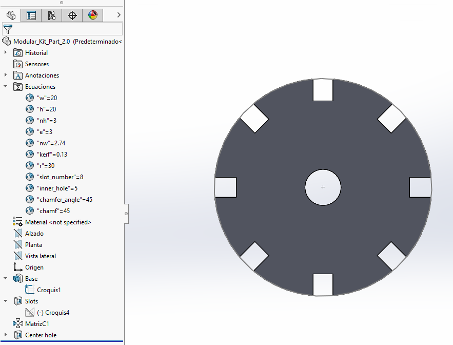
So in the end this part, allows you to generate designs for squares and rectangles (not much wider than higher by now), select center slots and/or corner slots, and you can input trough global variables: w (width), h (height), nw (notch width), nh (notch height), e (thickness ), and kerf (kerf, not shown on pictures). Obviously you can only enter the notch width or the thickness and kerf so it's calculated trought an equation.


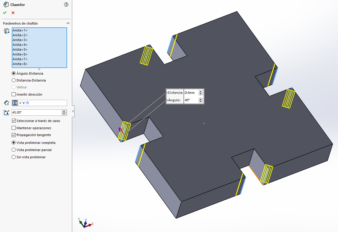
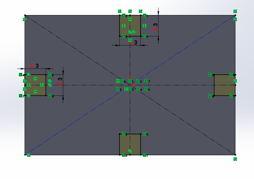
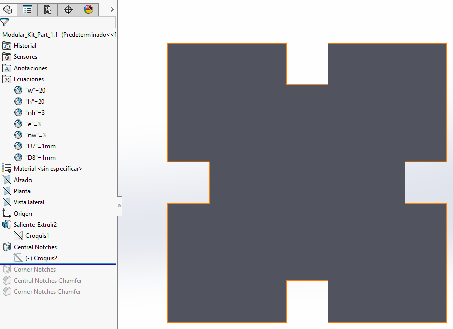
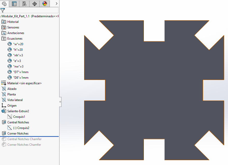
Then the chamfers are applied as I told as a 3D operation, but the slots on the corners needed another chamfer operation for one of the edges

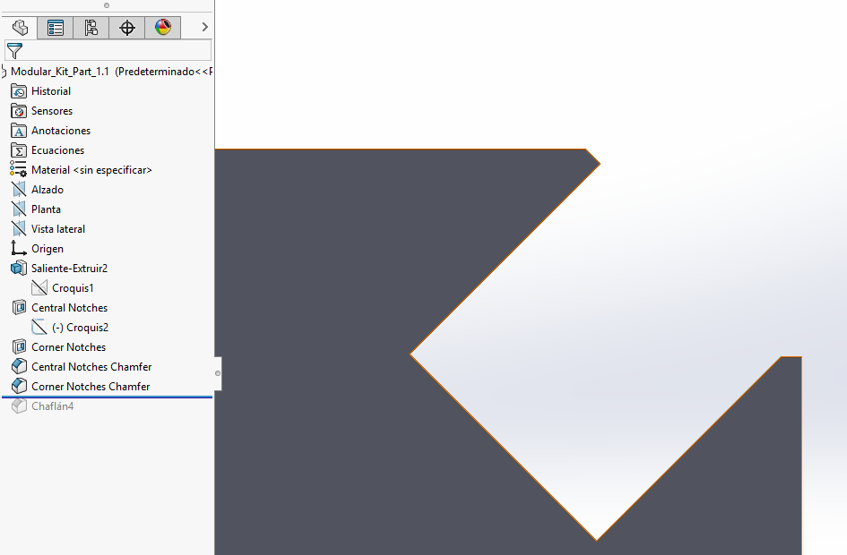

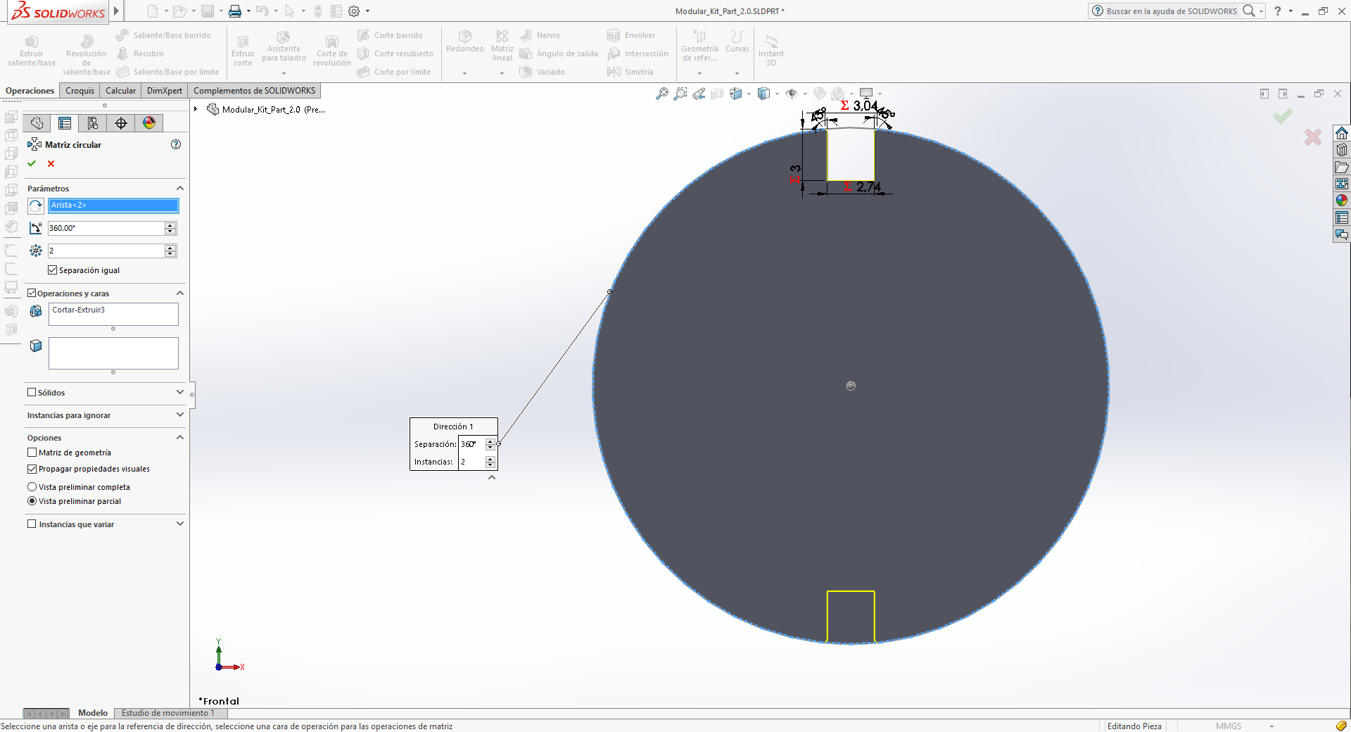
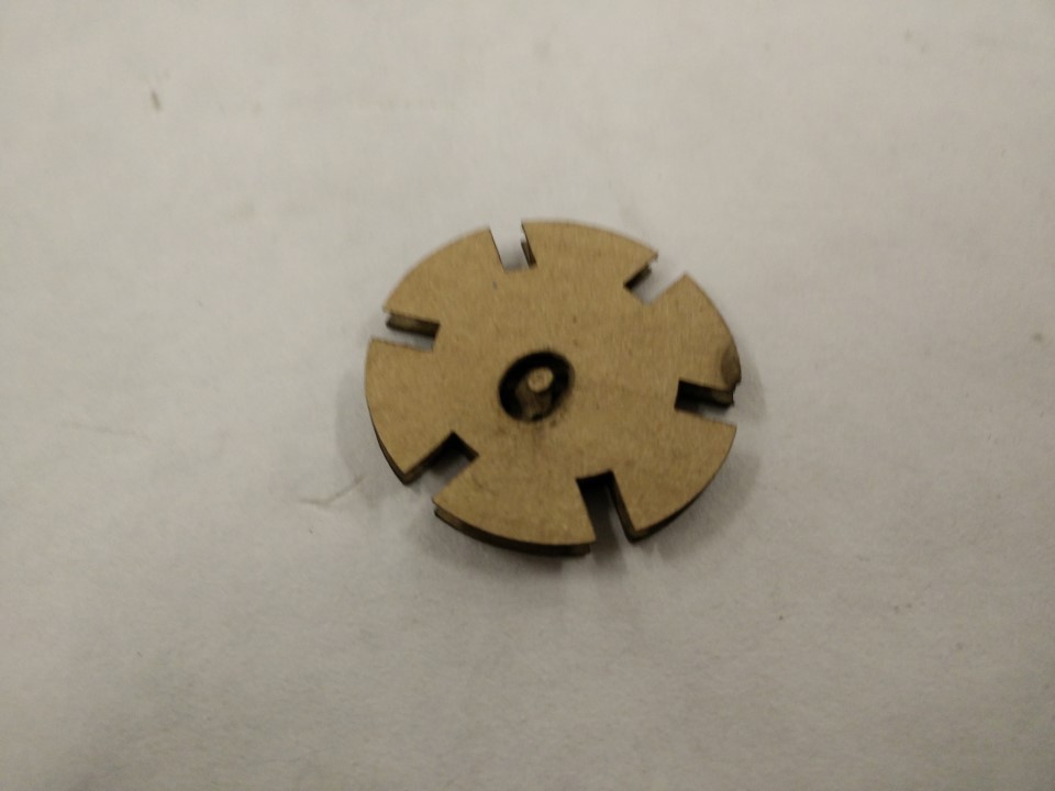
I've also created circular parts, can be with any number of slots equally distributed. For this, you cannot enter a global variable when doing the operation, but if you decide to show a number of instances, then you can smart dimension that and it's possible to parametrize that. I later encountered the same problem with an Offset entities at the corner part for width, but decided to do it by equations.


Tomorrow I will be testing the fitting and I'll be trying later to make parametric layouts trough assemblies. That way, I can make adjustments to slot size but have parts already prepared to laser cut.
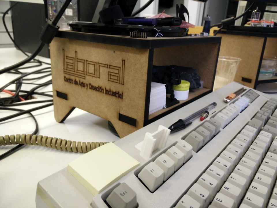
Finally could make the cutting part, even though I've made the parametric layout and it worked very well. In the end, I just wanted to cut a few parts and it was quick to arrange them manually. But I'll keep the parametric layout in mind for the future.
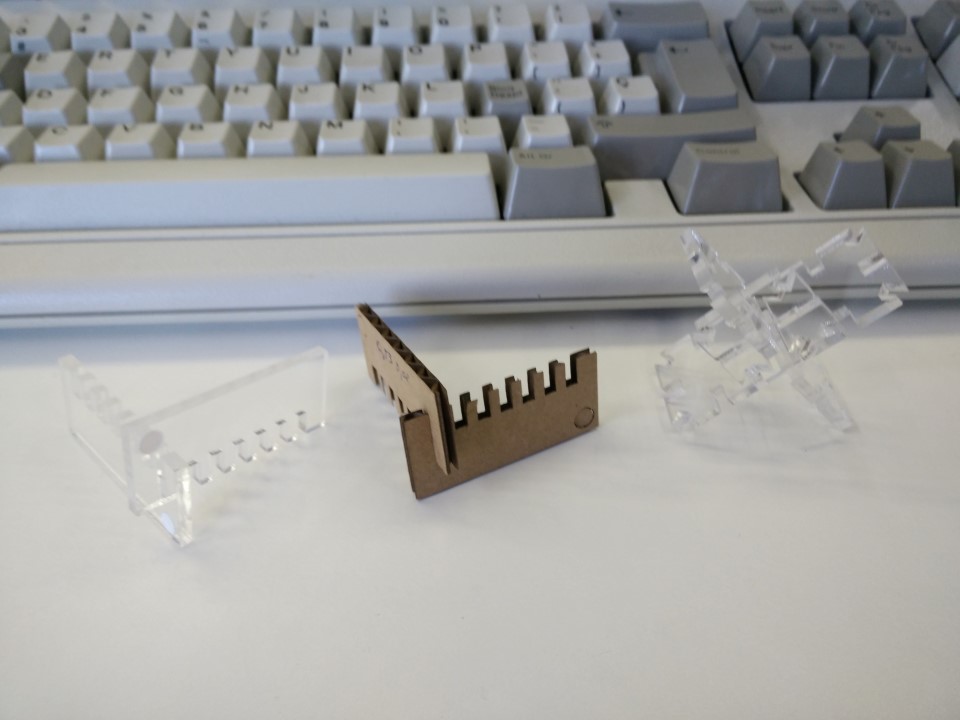
I've cut some simple parts using both cardboard and PMMA. The cardboard available is no the good quality one Neil mentioned on week 3 class. So I've used some acrylic left by some of the users of the fabLAB.
What I need to do to send files to our laser (Perezcamps 1610) is to import them on CorelDraw to them use the laser plugin to send the path to the cutter. So we are running CorelDraw X5 and it imports .dxf which is what I get from exporting in SolidWorks.
As for conclusions and discoveries, first is that unless you control perfectly the properties of a material, always test first. From one batch of MDF to another of the same supplier can be differences that would affect cutting parameters, so be prepared and have standardised tests to run on new materials. Kerf adjustment for properly dimensioning a part and kerf adjustment for press-fit are different things. For dimension is usually fixed and varies little from material to material but for press fitting it's totally different, cardboard being a less stiff material needs the slots to be quite narrow for press fitting, PMMA, on the contrary, needs a wider slot than the cardboard one as it won't be deformed by pressure when fitting, in any case if the slot is too narrow it may crack the part.
Another thing I've noticed after comparing parametric capabilities of SolidWorks and openSCAD is that SolidWorks is far more intuitive, openSCAD is far more homogeneous. For instance, dimensions work perfectly on SolidWorks, just make a global variable and edit on equations manager to change dimensions. But as for a circular pattern, the number of the elements of the pattern can't be entered as a global variable as you make the operation, you'll have to enter a number then enter the global variable dimensioning that, and as for angles, you can make the angle between elements of a circular pattern be shown as a dimension but then you won't be able to use that for parametric use.


Machines and software used
SO: Windows 10 and Windows XPInkscape
SolidWorks
CorelDraw X5
Perez Camps PC1610 laser cutter (power 60, corner power 50, speed 4000 mm/min)
Roland GX-24 cutter plotter (60ºblade, 100gf, 15mm/s)
400x500 heat press (no brand) (150ºC, 3 seconds, remove film then 10 seconds)
Files
You can download all files used for the kit here as a .rar
PS: sorry for the huge amount of carousels, I will get them better with sizing, but it's a good way to have lots of photographs in the same document without being too long.