Week 8: Embedded programming
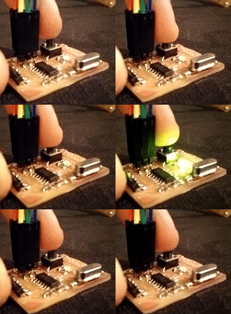
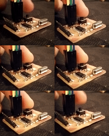
Ok, now that I have the fabISP programmed and working, it's time to program the helloKicad board that I've made for Electronics Design. Currently, I need a couple of capacitors to use the external clock, that I expect to get next week, but until that I will use the internal clock. First thing is to check that the fabISP connects with the ATtiny on the board, and as I was a bit rushed with electronics production is also the test that the fabISP works after being programmed.
Checking that the fabISP works and connects to the helloKicad board
It's been like ten years since I've learned microcontrollers at the university. And reviewing this week lesson, when it gets to the assembly code, it's familiar but I don't remember much. At the fabLAB we always used Arduino for most of the projects because the developments we made were for people that didn't know much about programming, but we could teach them a bit with Arduino so they would be able to modify the code for their project after they leave their residency at LABoral.
So what I'm planning to do with the helloKicad board is:
-Use GCC directly using Cygwin to compile the code and avrdude it to the board
-Use Atmel Studio on windows
-Use Arduino and then GCC
For the code I'll do a blink first, then when the button is pushed signal an S.O.S. trough the LED and finally use the ftdi cable to do some communication. But the priority would be to use as many environments as possible.
For installing gcc over Cygwin I've followed this tutorial just changing version 4.9.3 to 5.3.0.
So after testing a Hello World with GCC, I started a simple program to blink the LED. I'm following examples from the book: Make: AVR programming and examples are available at GitHub. Even though I've programmed PIC microcontrollers in C when I was at the university, I've always used an IDE like MPlab for Microchip PIC. I took a couple of makefiles, the one from the book and the one from hello.ftdi.44.echo.
I started modifying the makefile changing fuse values as I'm using the internal 8MHz clock on the ATtiny. By default the fuses are set to 0x62 and 0xDF for low and high respectively. That is using internal 8MHz clock but divided by 8 with CKDIV8 selected. So I need to change low fuse from 0x62 to 0xE2.
Reading fuses to file
So from the blink program, I remembered a bit about bitwise operations, ports and addresses. And I built some simple code first to blink, then to make an SOS, then to make an SOS when the button is pushed.

This is the C code
And the makefile
Due to a mistake writing != instead of |= when assigning DDRB byte I've noticed that you can appreciate the led blinking only that completely dimmed and only a small dot of light is seen.
C code for the SOS
Next stop is generating the code with Arduino and using GCC to compile the code and avrdude to load it to the board. This was pretty straightforward, just installed the ATtiny board adding https://raw.githubusercontent.com/damellis/attiny/ide-1.6.x-boards-manager/package_damellis_attiny_index.json to additional URLs for the board manager. I've guessed pin numbers would start 0 for PA0, 1 for PA1 and increase with PORTB pins. So for this I just made the blink when the button is pushed.

The sizes of the programs were 96 bytes for the SOS program using GCC vs 906 bytes for the program using Arduino language, this is not linear, this is a fixed cost, so Arduino libraries for the ATtiny are about 800 bytes out of 4096 in the case of the ATtiny44, which is around 20% of total memory.
Arduino sketch, blink when button pressed
As for the other part of the assignment which was to read a microcontroller datasheet, I didn't really care about that week, but now, writing after project presentation and updating and making a little self-evaluation, I've noticed that it isn't documented on my page. The reason is that it is not something I'm doing for the first time.
I agree with what Neil pointed about taking a whole look at the datasheet just to be aware that all possible information regarding the µC will be there even when you don't even need it. I left the Industrial Engineering degree with a supposed intensification on electronics and automatics without knowing more than a third of what is on a datasheet like that. Even though is true that I can study the rest. So I imagine it will be overwhelming for students with no previous electronics background to face that kind of datasheet.
What I look at when reading a µC sheet is most of the time either stuff I need, like memory, communication ports (# of SPI, I2C, UART...) ADC/DAC capabilities, pinout, packaging information... and stuff it needs like power supply and consumption, additional components like the clock or its discharge capacitors... And from there and depending on the needs of the project one should get deeper in some sections.
Machines and software used
SO: Windows 10GCC
avrdude
Arduino IDE
Files:
helloKicad.cmakefile
helloKicadArduino.ino