Week 11: Input devices
For input devices I wanted to test several a couple of things, first one is reading the ADC. For that I've put on my board a couple of voltage outputs, one is a hall sensor that outputs a proportional voltage to the magnetic field it senses. The other one, even so discouraged by phototransistor being a better component, an LDR that I had available as I'm a bit short on electronics supply. That way I'll have to read the ADC and see what happens when you need to read multiple analog inputs.
The other thing is to communicate with an I2C device, I have a 10 DOF IMU that different to integrated IMUs like the MPU6050, there are several I2C devices: magnetometer, accelerometer, barometer, and gyroscope.
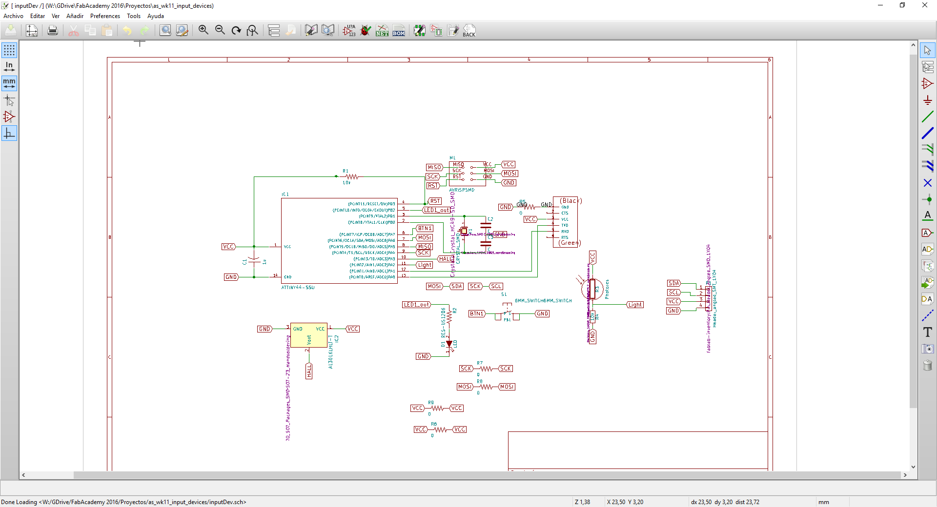
In the end, I only managed to get time to use an LDR and a Hall effect sensor. Those are both analog inputs, one directly from the sensor and the light one from a voltage divider adjusted to the value of the LDR. The board design was just a simple modification from the board made for week 8. I have also added a led to get an on-board output to check if it is measuring something. It also has an FTDI connector for serial communication and a button. When deciding what pin should I connect this magnetometer to, I went to the datasheet and checked the pinout so the sensors are on the right part of the board while the clock, led and button are on the left side of the board. Of course, when using certain peripherals you have to check they're just available, but when using analog or digital pins, if there are more than needed, I take some time deciding what pin I would connect to in order to have less trouble while routing the board.
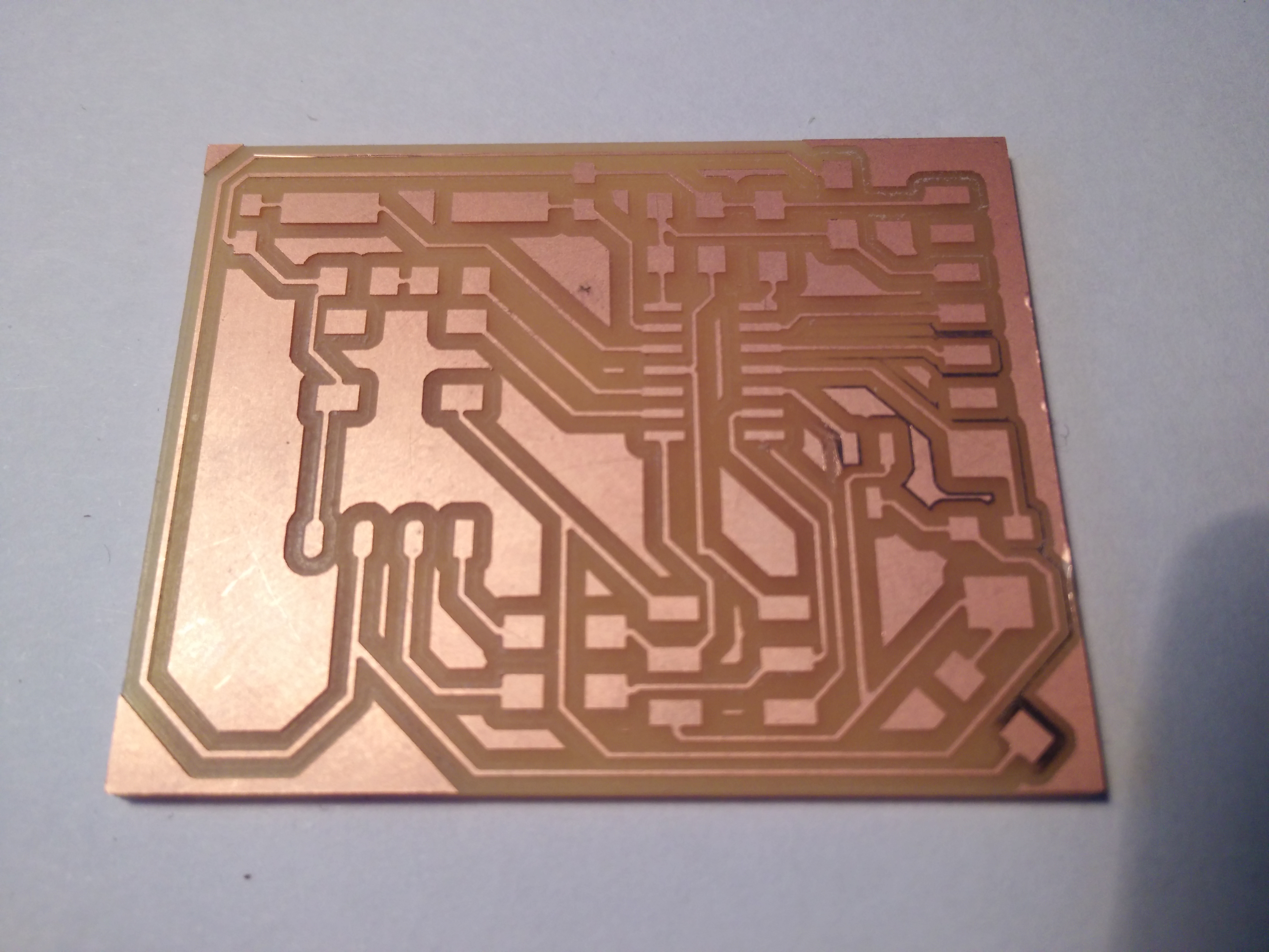
The PCB milling was pretty straight forward but I need to change the martyr, because as you can see in the fourth picture of the carousel below, on the right bottom corner the first couple of offsets didn't get to the substrate. It is not a problem because it doesn't connect anything, but shows the importance of a very flat bed when milling this thickness.
As for programming I started from Neil's HelloMag.c and just had to change the pin I'm using for the analog inputs and the number of bits to set as Vref at line 36 as the ATtiny44 has only 2 pins configurable while the original (I think was ATtiny85) had 3 bits for that. All that information was found in the datasheet.


Video
In the video, first when I move the light away from the sensor the led starts blinking fast. Then I grab some magnets and approach them to the hall effect sensor and the fast blinking starts for some cycles, then it goes back to slow blinking.
Machines and software used
SO: Windows 10KiCad
Roland Modela vPanel
Roland Modela MDX40
0.4mm PCB routing mill (traces)
2mm PCB routing mill (outline)
Files
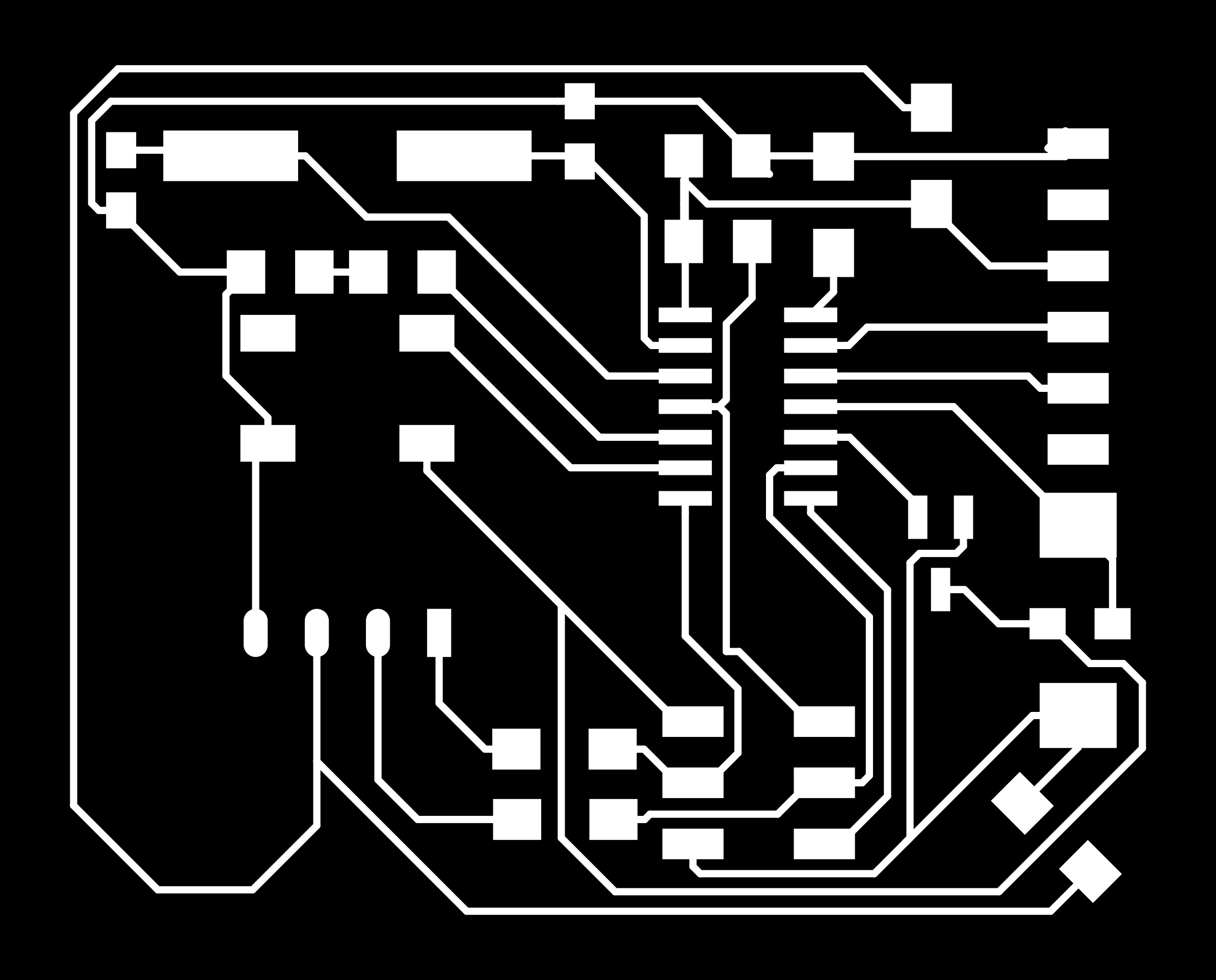
input_dev_cutout.pnginput_dev_traces.png
Kicad files
inputDev.proinputDev.sch
inputDev.kicad_pcb