
ADITYA BHATT

Week-6 ELECTRONIC DESIGN
ASSIGNMENT
This week assignment is to create an echo hello-world board using eagle and redesign along with addition of components (at least two) LED and switch.


I have used eagle which is a circuit design tool to make the echo hello-world board. I have been working with circuits since quite long now so this is not very new to me. I understand the terminology of electronics and which part plays what role in a particular circuit as well as the flow and distribution of current in circuits.
In this circuit we are using a microcontroller which we will programme later.
Microcontroller
microcontroller is a control device which incorporates a microprocessor. For the understanding its use I have refered the ATtiny44 microcontroller’s data sheet .The data sheets have more description about a particular microcontroller and its configuration with pin diagram, some information and an overview of its application in different circuits.
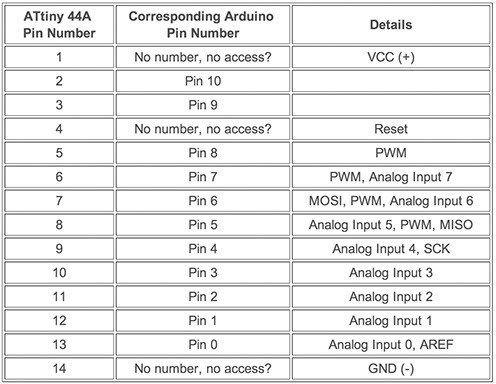
Pin configuration Of Atiny44
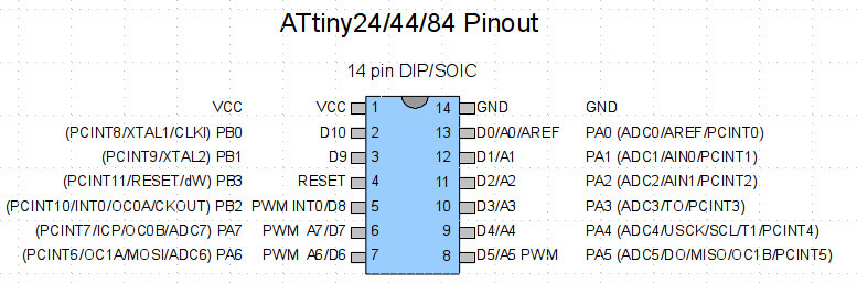
pin description
VCC - Supply voltage.
GND – For grounding pins.
PORTB(PB3:PB0) – Port b is a 4-bit bi-directional input and out put port.in that PB3 which has RESET capacity also it is used as an input or output pin.
PORTA(PA7:PA0) - Port a is 8-bit bi-directional input or output buffers have symetrical direction.
SUMMARY
WIRING , CONNECTION, AND PROGRAMMING-
six wires isp programming
SCK(serial clock):programming clock,generated by the In-system programmer(Master)
MOSI(Master Out-Slave IN):Communication line from In-system Programmer to target AVR being programmed
MISO(Master in-Slave Out):Communication line target Avr to in system programmer
GND(common ground):it connect to the ground
RESET:to enable in-system programming
VCC:to allow simple programming of targets operating at any voltage,the in-system programmer can draw power from the target .
GENERAL INFORMATION-
Input and output packages Operating Voltage Speed Grade
20-pin qfn/mlf 1.8-5.5V 0-4 MHz @1.8-5.5v
14-pin SOIC and PDIP 2.7-5.5 V 0-10 MHz @2.7-5.5v
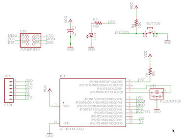
MY INPUT AN CHANGES
I thought of redesigning the board and adding 2 led's and a switch to the board. I also added a little bit of text to it.
Components list for the Echo Hello ISP-
Micro-controller
Crystal 20Mz
USB connector
Ribbon connector
Zener diode
Jumper wire
Switch
Resistors
Capacitors
LEDS
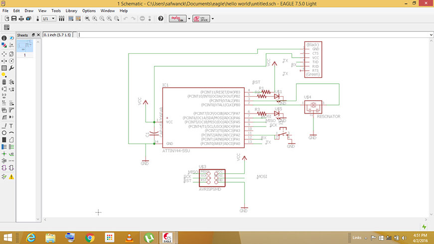
DESIGNING THE BOARD IN EAGLE-
For beginers, tutorials are available on youtube and on fab academy tutorials also.
1) Open new and click on schematic.
2) click “library->use” then select the fab library and open it.

5) Making the Board.....
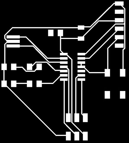
6) I set up all the necessary parameters and designed the board. I also added little bit of text there.
the board designs are doing the switch to board view,in here we arrange the components place,board shape .after the design to check any connection problem occurs or not for that I am going to autoroute ,then I set top=auto and bottom=N/A , because I wanted a single side board and click continue that time it root automatically.but I did not to get 100% in the first time.also, we can see where is the connection problem when we rooting time and I change the place of components finally got 100%.manual routing option also has the eagle.
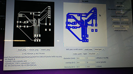
7) Final step is to export the image. click file->export->image
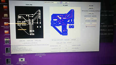
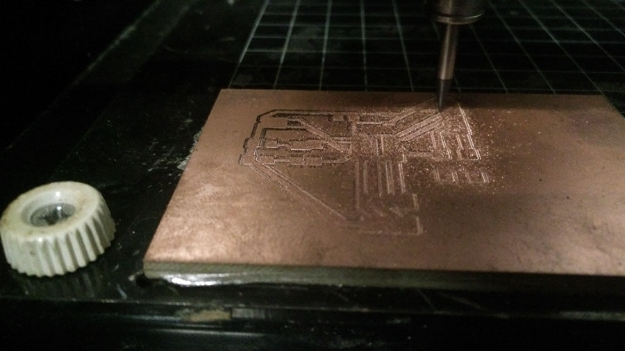
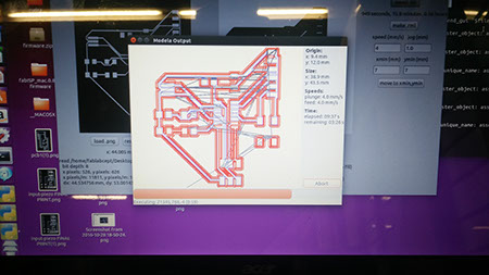
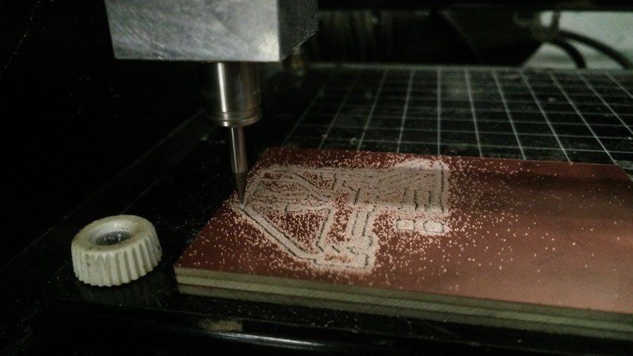
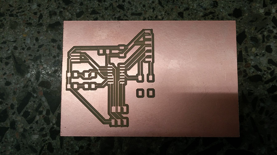
Now that the designing part is over, we can begin with milling of our board.
MILLING
Files-
.jpg)
.jpg)
.jpg)
.jpg)
.jpg)
.jpg)
.jpg)


3) for adding the components in the schematic page, type “add” in the comment box then enter it that time the eagle library are open in that we click the fab,we can see components are directly under the fab folder In that choose what are all the components we needed and add it to the schematic page
4) Now select and add all the components that are required.
Components we need for the Hello ISP board:
Micro-controller
Crystal 20Mz
USB connector
Ribbon connector
Zener diode
Jumper wire
Switch
Resistors
Capacitors
LED