
ADITYA BHATT

Week-11 INPUT DEVICES
Assignment
-Measure something: add a sensor to a microcontroller board that you have designed and read it
Learning outcomes:
1)Demonstrate workflows used in circuit board design and fabrication
2)Implement and interpret programming protocols
Tasks:
Described your design and fabrication process using words/images/screenshots.
Explained the programming processes you used and how the microcontroller datasheet helped you.
Explained problems and how you fixed them
Included original design files and code
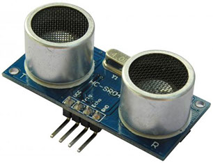
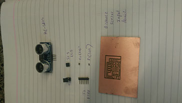
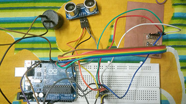
This week's task is to build a sensor which takes input. I have chosen the Distance sensor HC-SR04. It detects an object in front of it. Such sensors are used in submarines to detect objects. I have programmed it to detect a person when he or she climbs a stair. I have used a buzzer
which gives out sound which a person walks in front of it and I have progammed the frequency of vibration of the buzzer too!
HC-SR04 Specifications
-Working Voltage: DC 5V
-Working Current: 15mA
-Working Frequency: 40Hz
-Max Range: 4m
-Min Range: 2cm
-Measuring Angle: 15 degree
-Trigger Input Signal: 10µS TTL pulse
-Echo Output Signal Input TTL lever signal and the range in proportion
-Dimension 45 * 20 * 15mm
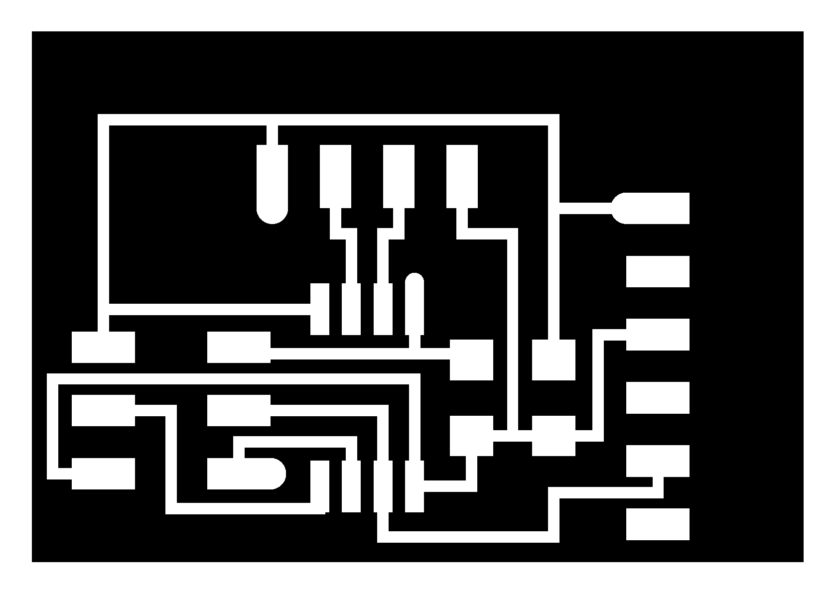
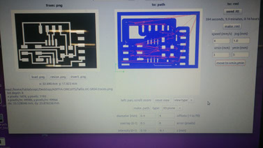
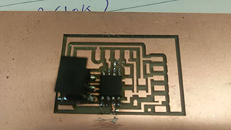
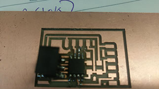
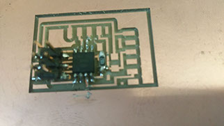
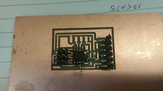
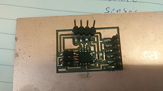
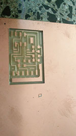
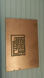
a) Board traces b)Components of the board c)Interior of the board
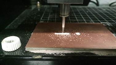
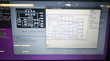
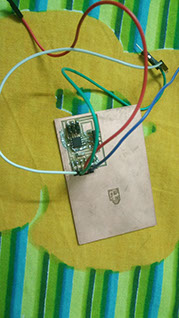
MILLING THE BOARD-
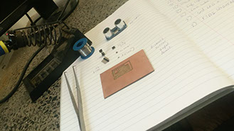
SOLDERING THE BOARD-
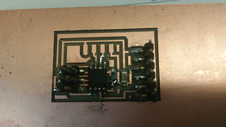
Once the code is uploaded to the board I tested wether the programe runs sucessfully or not.
I
I have used the arduino to give power to my circuit.You cay use another way to power you board.


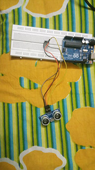
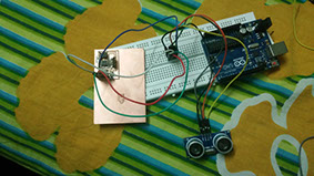
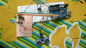
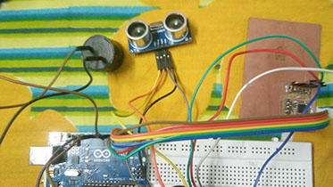
1) I connected all four pins of HC-SR04 on the bread board...
2) Then I connected the pins of the input devices from the board to the sensor.....
3) Then I connected the pins from the board to arduino so as to programe it and give it power.
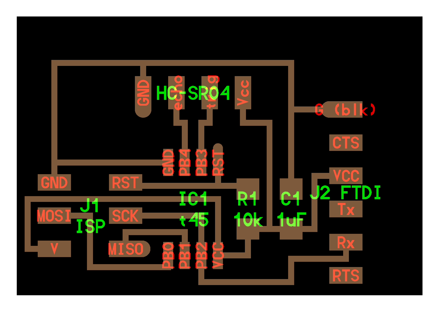
The pin out diagram to connect arduino and the board is given in the begining of the page.
Then I uploaded is code to my arduino-
int Buzzer = 8;
void setup() {
Serial.begin (9600);
pinMode(trigPin, OUTPUT);
pinMode(echoPin, INPUT);
pinMode(Buzzer, OUTPUT);
}
void loop() {
int duration, distance;
digitalWrite(trigPin, HIGH);
delayMicroseconds(1000);
digitalWrite(trigPin, LOW);
duration = pulseIn(echoPin, HIGH);
distance = (duration/2) / 29.1;
if (distance >= 80 || distance <= 0){
Serial.println("no object detected");
digitalWrite(Buzzer, LOW);
}
else {
Serial.println("object detected");
tone(Buzzer, 400); // play 400 Hz tone for 500 ms
delay(500);
tone(Buzzer, 800); // play 800Hz tone for 500ms
delay(500);
tone(Buzzer, 400); // play 400 Hz tone for 500 ms
delay(500);
tone(Buzzer, 800); // play 800Hz tone for 500ms
delay(500);
tone(Buzzer, 400); // play 400 Hz tone for 500 ms
delay(500);
tone(Buzzer, 800); // play 800Hz tone for 500ms
delay(500);
noTone(Buzzer);
}
delay(300);
}
Files to be uploaded-
Now that my board is soldered and ready to be used I did the following...