
ADITYA BHATT

FINAL PROJECT
Project concept-
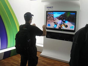
The project concept is to control a robot with gestures. I was very influenced by gesture contol when I played Gesture controled games in XBOX. So I thought why not control a robot with hand gestures instead of using orthodox boaring remote controls. Such toys are available in market but they are quite
expensive so I thought using simple component and make it affordable.
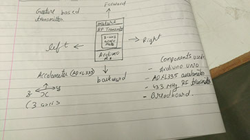
The different gestures that have been mapped to the direction of the bot are-
Hand parallel to the ground-stationary
Hand tilted forward-forward
Hand tilted backward-backward
Hand tilted right-right
Hand tilted left-left
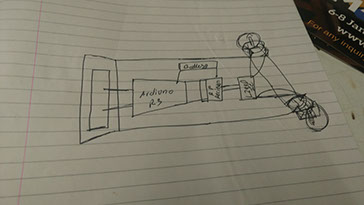
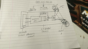
Planning on paper
2D Desgining
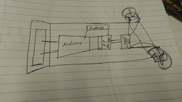
I started the making of the chassis first as a 2-D sketch. I always try to keep things as simple as possible and start with simple tasks gives confidence.
.jpg)
I then made a few structural changes in my 2-D design. I added wheels and saw wether it matches the frame or not.
.jpg)
I designed the wheels using sketch-up as I love to learn new softwares and sketch-up is quite simple to use. I designed my wheels in sketch-up
.jpg)
3-D designing of my files
Couple pf images below show the wireframe images of my car chassis.
.jpg)
.jpg)
After my 3-D images were made, I used 3-D builder which comes in windows 10 by default to view my files and virtually assemble them.
.jpg)
.jpg)
.jpg)
.jpg)
I loaded the files in cura and saw the printing time. As the time was 6.38 hours I decided to print them seperately.
.jpg)
.jpg)
.jpg)
3-D printing the files and assembling them.
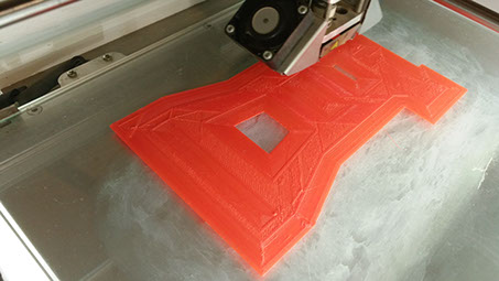
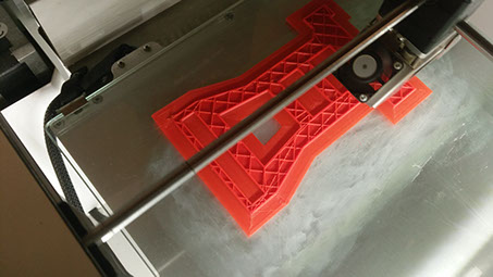
I have used ABS plastic for the printing of the final project chassis.
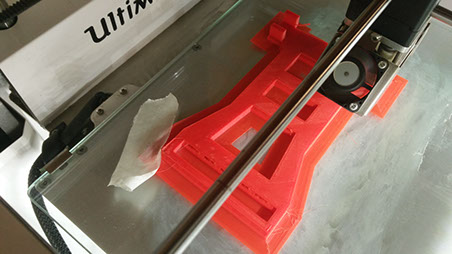
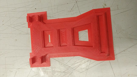
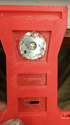
My chassis is printed just as I wanted.
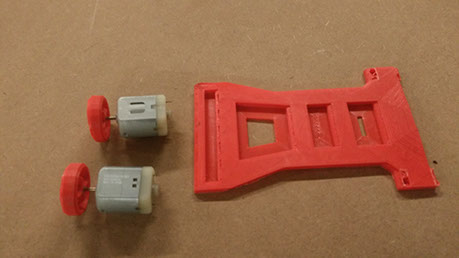
After my chassis was printed perfectly, I moved ahead with the printing of my the wheels for my car.
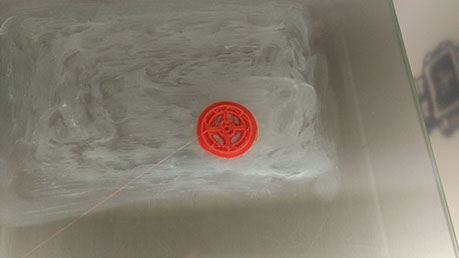
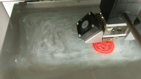
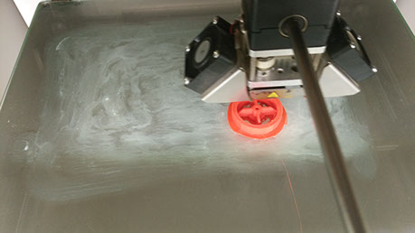
The printing of the wheels got over quite quickly so I moved on with testing the strength of the complete unit. The results were also extremely satisfying.
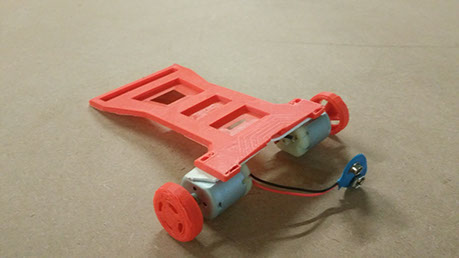
I connected the 9v battery holder to just do a simple test which was succesfull undoubtedly.
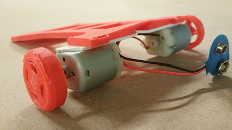
It was very easy to assemble the unit. I just used double sided tape for temporary use.
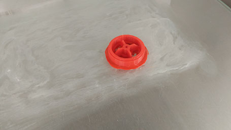
The wheels fix perfectly with my dc-motor. I was just a bit anxious about this before printing the wheels but It now gives me relief.
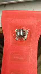
castor wheel
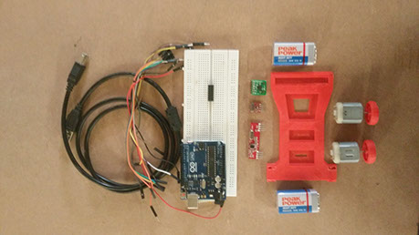
Almost all the parts that will be needed for making the final project are here.
The video for testing of my chassis is given below
I started to gather all the parts that I would probably require to start off with.
Parts shown in the above Images include-
1) Breadboard
2) Arduino(for programming)
3)Arduino cable
4) 9v batteries
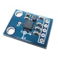
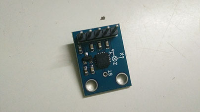
5) Adxl335-accelometer
6) Rf transmitter and reciever
7) L293D Motor driver IC
8) 2 Dc motors (30 rpm)
9) Jumper wires(male to male, male to female and female to female)
10) Robot chassis( along with caster wheel)
Now that I had the parts needed to make the final project, I started with interfacing the accelometer and then making the gesture controlled transmitter.
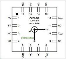
The accelerometer I am using is Adxl335.
The specifications of this is as follows-
FEATURES
3-axis sensing
Small, low profile package
4 mm × 4 mm × 1.45 mm LFCSP
Low power : 350 μA (typical)
Single-supply operation: 1.8 V to 3.6 V
10,000 g shock survival
Excellent temperature stability
BW adjustment with a single capacitor per axis
RoHS/WEEE lead-free compliant
APPLICATIONS
Cost sensitive, low power, motion- and tilt-sensing
applications
Mobile devices
Gaming systems
Disk drive protection
Image stabilization
Sports and health devices
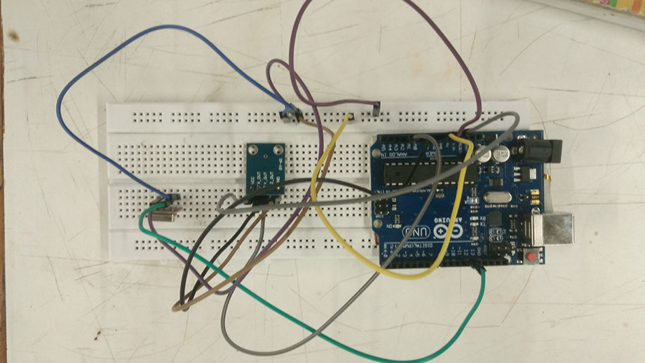
Now that we know we know what exactly accelerometer can be used for, we will interface it with arduino to obtain output and print the and x and y positions of the accelerometer on the serial monitor.
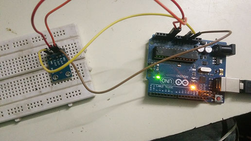
The pin connection of arduino with accelerometer is as follows-
1) gnd-gnd
2)vcc-3.3v
3)x-A0
4)y-A1
The now upload the code given below on arduino-
//Coded by Aditya_bhatt@Fablabcept
int xPin=0;//Connect x pin of adxl335 to pin A0
int yPin=1;//Connect y pin of adxl335 to pin A1
void setup()
{
Serial.begin(9600);//Initialise the serial connection
}
void loop()
{
int xval=analogRead(xPin);
int yval=analogRead(yPin);
Serial.print("xval=");
Serial.println(xval);//Use xval to determine threshold for different directions
Serial.print("yval=");
Serial.println(yval); //Use yval to determine threshold for different directions
delay(2000); //used to display values after 2s delay
Serial.print("\n");//print after 2s in a new line
}
The output obtained for change in the x and y positions is shown in the video below.
Now that the accelerometer is interfaced, we just need to add the rf transmitter and upload the code. With this, our final project transmitter is ready!
The connection of arduino with rf transmitter is as follows-
A)GND-GND
B)DATA-D12
C)VCC-5V
After we are done with pin connections we just need to upload the code given below-
//Connect the Transmitter data pin to Arduino pin 12
//If you don't want to use pin 12 use vw_set_tx_pin(transmit_pin), with transmit_pin being desired pin ,in void setup
//Refer to the documentation in link for more details
#include <VirtualWire.h>
int xPin=0;
int yPin=1;
int ledPin=13;//led on pin 13 is ON except when transmitter is parallel to the ground
void setup()
{
vw_setup(2000);//Bits per second
pinMode(ledPin,OUTPUT);
//Serial.begin(9600);//Initialise the serial connection debugging
}
void loop()
{
int xval=analogRead(xPin);
int yval=analogRead(yPin);
//Serial.print("xval=");
//Serial.println(xval);
//Serial.print("yval=");
//Serial.println(yval);
//delay(1000); //used to display values after 1s delay
//Serial.print("\n");
if ((xval>370 && xval<385) && (yval>360 && yval<380)) //stationary or stop(transmitter parallel to ground)
{
digitalWrite(ledPin,LOW);
send("s");
}
else
{
if ((xval>395 && xval<416) && (yval>360 && yval<380)) //forward(transmitter tilted forward)
{
digitalWrite(ledPin,HIGH);
send("f");
}
if ((xval>345 && xval<365) && (yval>365 && yval<381)) //backward(transmitter tilted backward)
{
digitalWrite(ledPin,HIGH);
send("a");
}
if ((xval>370 && xval<380) && (yval>335 && yval<355)) //left(transmitter tilted to left)
{
digitalWrite(ledPin,HIGH);
send("l");
}
if ((xval>370 && xval<390) && (yval>385 && yval<395))//right(transmitter tilted to right)
{
digitalWrite(ledPin,HIGH);
send("r");
}
}
//delay(1000);
}
void send(char *message)//send function definition
{
vw_send((uint8_t *)message, strlen(message));
vw_wait_tx(); // Wait until the whole message is gone
}
The output of x and y values of my accelerometer positions are shown in the test video below