Week 7
computer-controlled machining
Assignment
- Make something big
Week workflow
Here is how I see the week's flow :
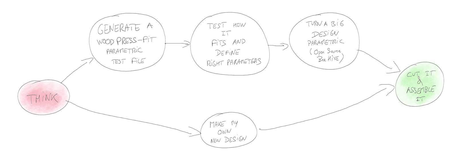
Flow chart for this week
Table of content :
- Design a machining test File
- Machine (cut) the test file
- Turn an existing design parametric
- Machine it and assemble it
- Try fabmodules
- Using VisualMill for Solidworks
- Make my own design
- Source files
The machine we'll use : A shopBot
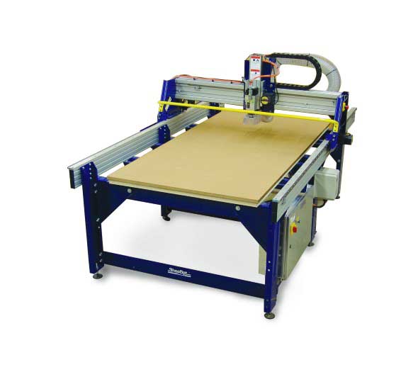
The ShopBot
STEPS
Design a machining test File
First thing I want is to be able to find the right parameters for my machining based on :
- The fitting system I want to use
- The nature of the material I'm using
- The machine I'm using
- The thickness of the material I'm machining
- The tool bit I'm using
- The the age of the captain
Practically, I want to find the right "clearance gap" between the parts of my object in order to be able to assemble it the way I want later
This is a perfect situation for Grasshopper
I'm thinking of using the dogbone method :
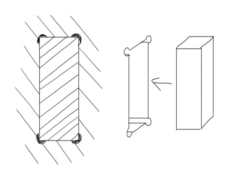
The Dog Bone method
So I design a grasshopper algorithm to make dogbones with different clearance gaps.
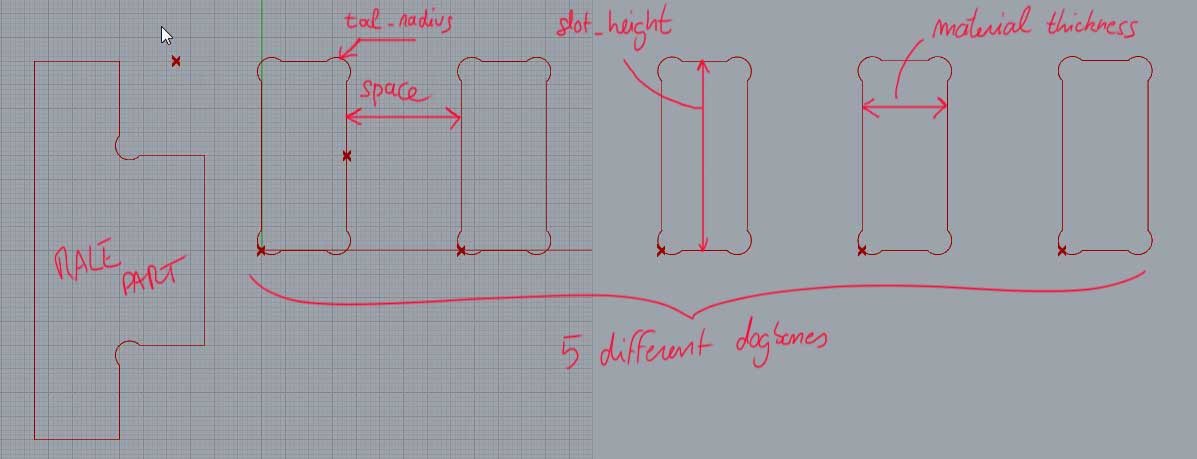
I first design it on the paper, well, on the whiteboard..just to find the basic flow of the algorithm and the math behind it, nothing to do with Grasshopper :
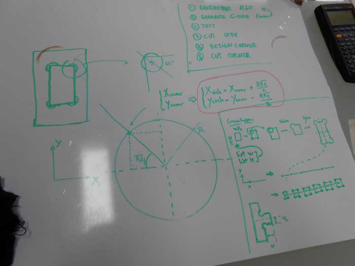
Designing the algorithm on paper
Then I do it in Grasshopper :
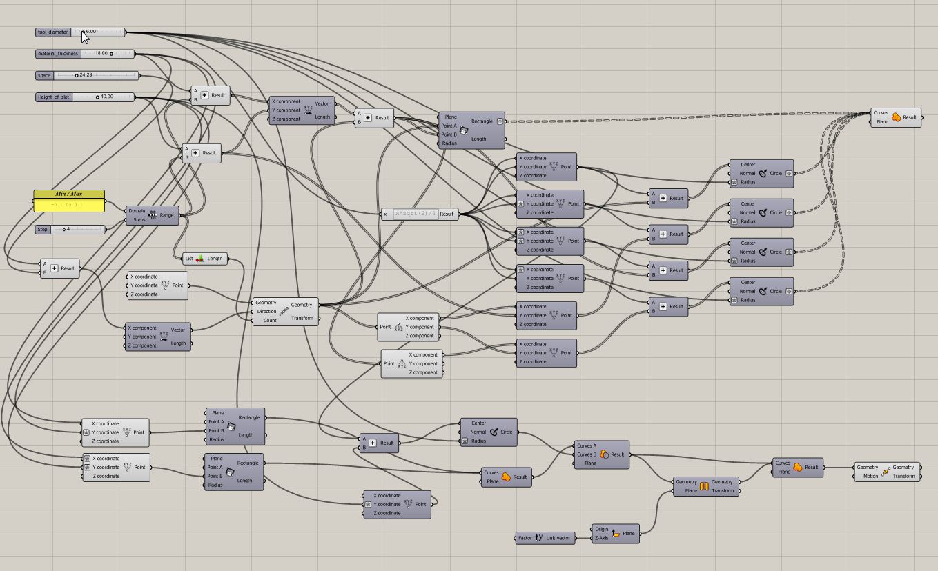
The algorithm in Grasshopper
Here is what it outputs :
The algorithm generates different dogbones
I also dynamically create the male part to test with.
I want to be able to dynamically control the space between the slots, the height of the slots, the material thickness, and the diameter of the tool.
More importantly I want to dynamically define what range of clearance gaps I want to cover and how many different values I want in that range :
My inputs are then :
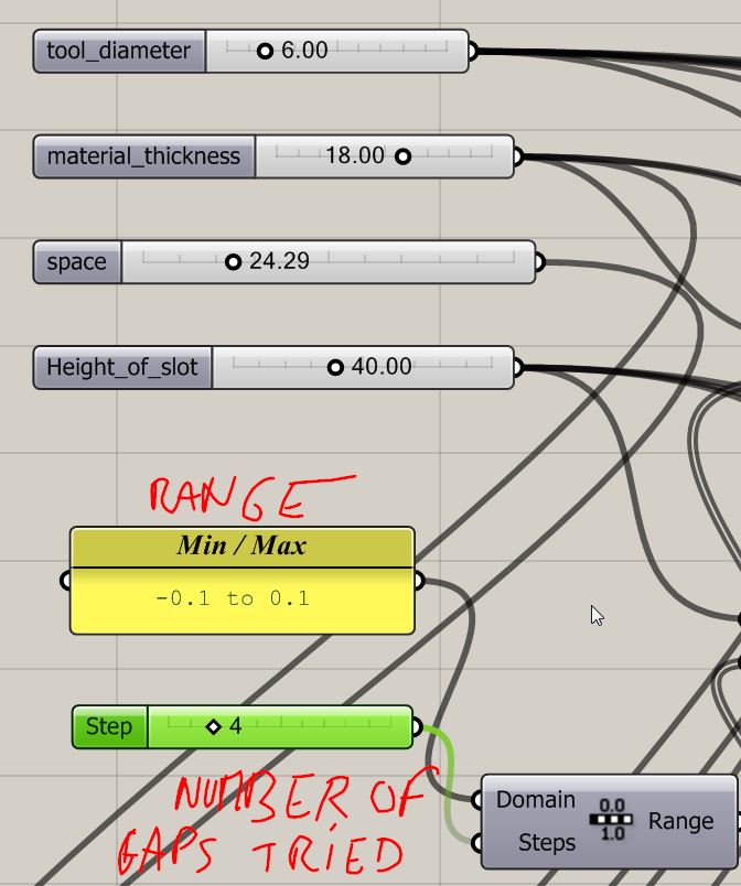
The inputs
If we overlap all the slots we can clearly see what it does (click to zoom):
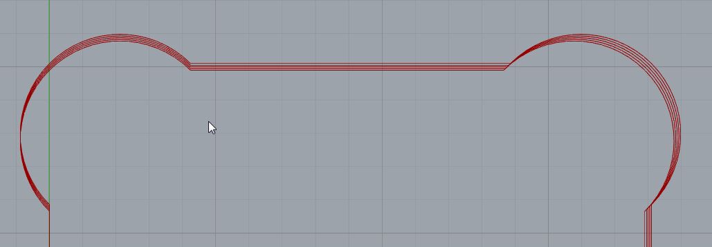
All the slots overlapped (click to zoom)
As I said, it makes dogbones with different clearance gaps.
Now we're ready for some cutting !
Machine (mill) the test file
The machine doesn't speak Rhino.
We need to generate a simple set of instructions that it can read and follow.
This is called a gcode. It's a text file with all the basic moves the machine will have to make to cut our design.
I'm using a plugin in Rhino to generate the Gcode : RhinoCam
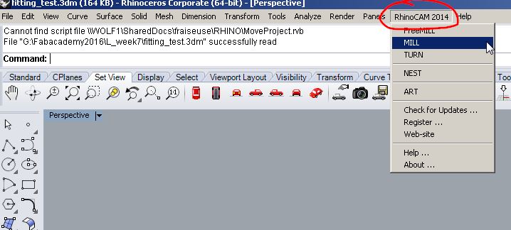
RhinoCAM from the Rhino menu
It opens two windows :
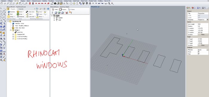
The RhinoCAM Graphical User Interface (GUI)
Here we'll create our machining jobs and specify the relevant parameters.
In my case I created three jobs :
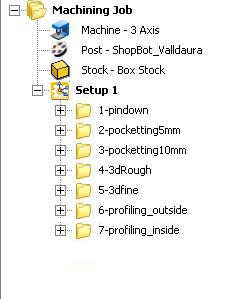
Three Jobs
I also specify the wood stock I'll mill my design in :
In my case I created three jobs :
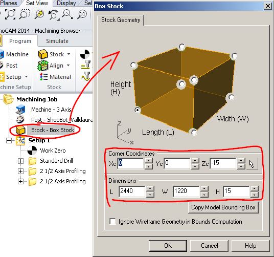
Specifying the stock
First I mark with a drilling operation where I will put the screws to hold my material on the sacrificial board of the machine.
Second, I cut the interior of the dogbones (Profiling).
Lastly, I cut the outside of the male part (profiling)
If we double click on a machining operation, it opens a parameter window with many "tab menus" (not the "machining tabs" we'll talk about soon) :
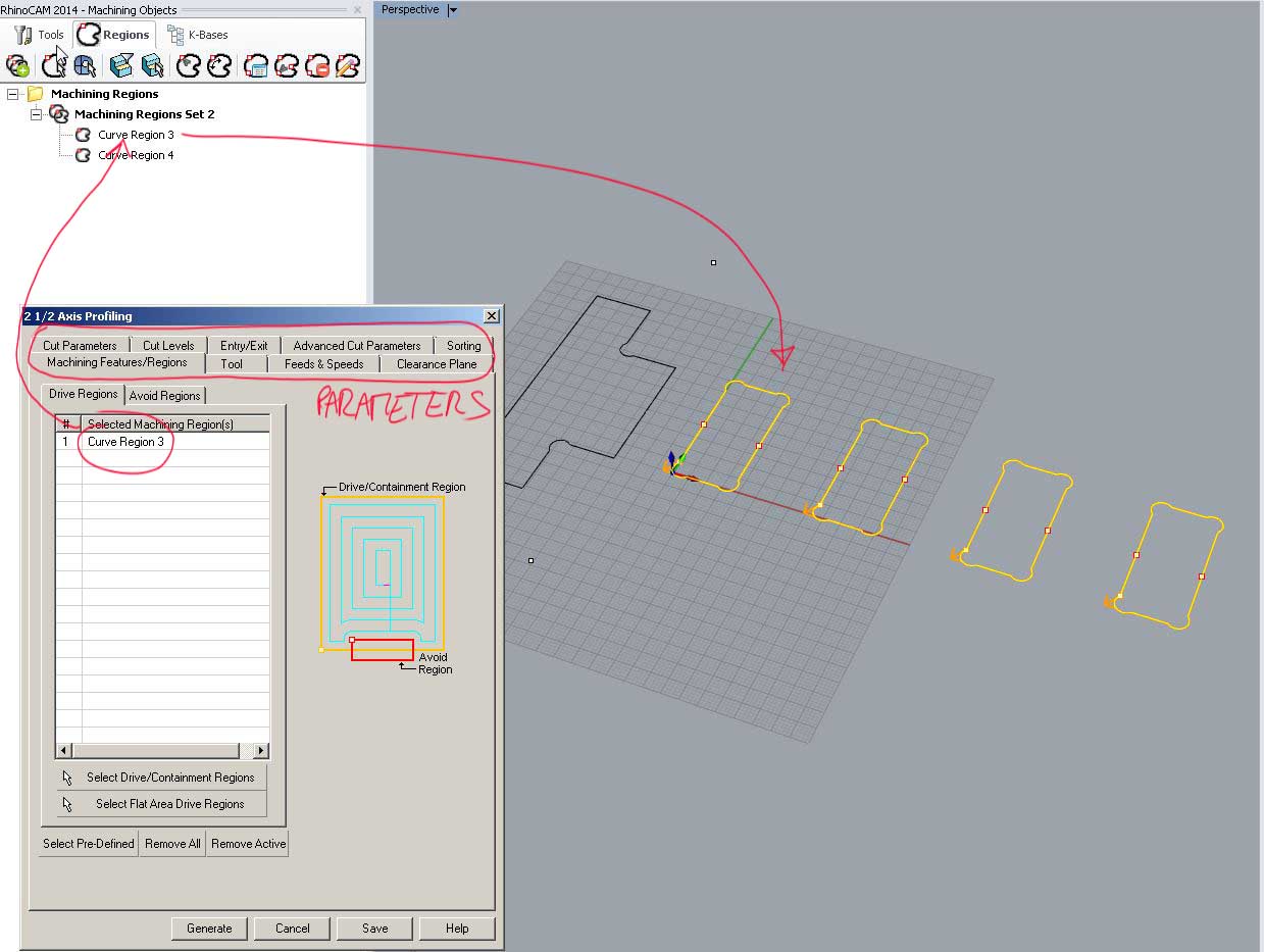
The RhinoCam parameters window
Here we enter all our cutting parameters such as the depth, speed, passes etc. related to the geometry we selected in Rhino
For example, the Cut levels tab :
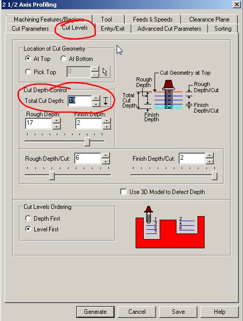
The Cut Levels Tab
We will make our test in an OSB board of 18 mm. To be sure it'll cut it completely, we enter 19mm and we choose passes of not more than the size of our milling bit (6mm)
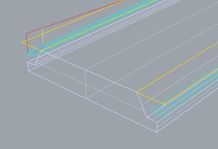
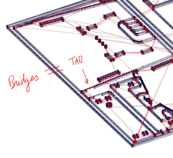
It then generates a tool path that we can see in the Rhino viewport :
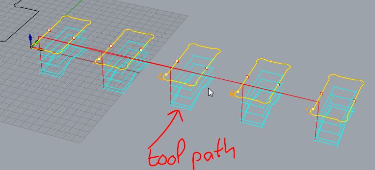
Toolpath in Rhino
Notice that I'm using "machining tabs" to hold any piece that could fly away during the milling after being completely cut :
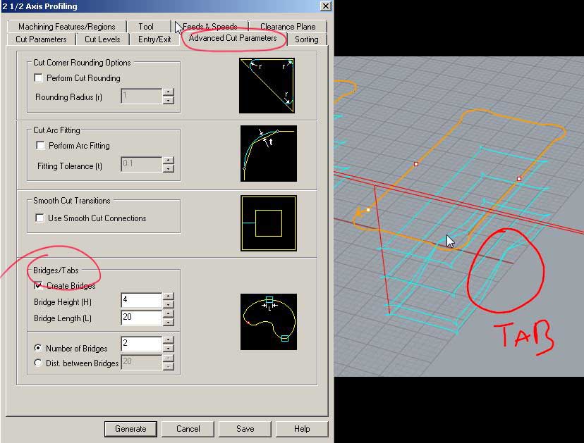
Setting the tabs parameters
You can set up the position of the tabs thanks to these icons :
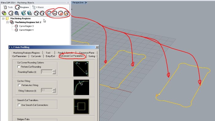
Setting the tabs positions
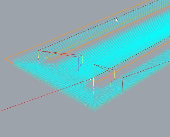
Once we've played with the parameters and we're happy with the tootlpath, we can simulate it :
Simulation of the milling operation
Then we need to export that 3d rhino toolpath to a text file that contains all the moves that make up this toolpath
This is where the "translator" comes in to help ShopBot and Rhino talk to each other. It's called a post processor.
The postprocessor converts the tool path in this :
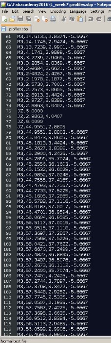
The gcode, a text file
We can specify it there :
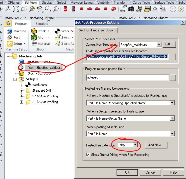
Specifying the post processor
It contains all the moves the bit will have to do to follow the toolpath that we generated in Rhino
Alright, Let's put these files on a usbkey and go to the shopbot.
Milling our test file :
Simulation of the milling operation
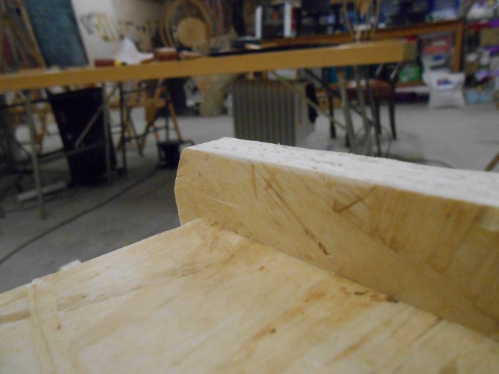
And testing the dogbones afterwards :
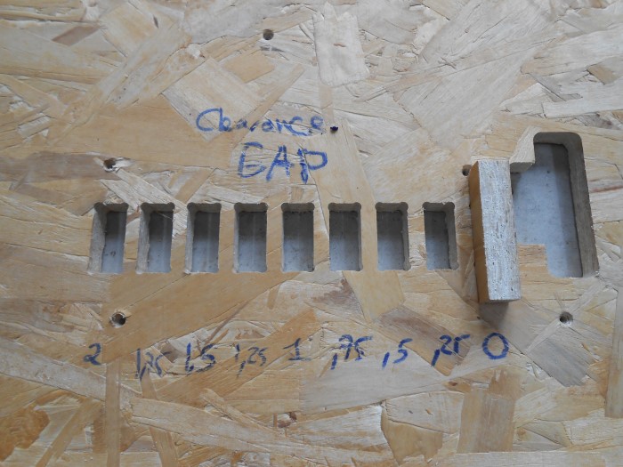
Our first test cut
Here is the male part :
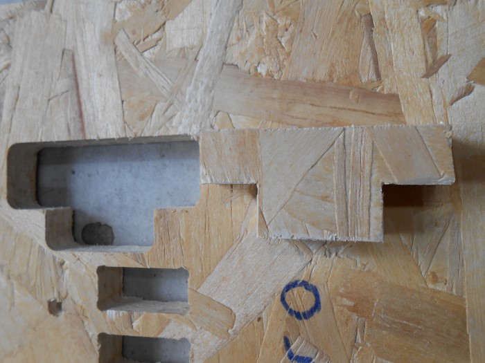
The male part
My clearance gap ranges from 0 to 2mm. 0 is very tight and 2 turns out to be completely loose.
I want to try finer values. So I return to my grasshopper algorithm and I create another range : from -0.1 to 0.1 with 5 intermediate values.
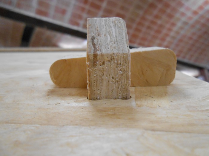
We generate a new gcode. And here is the second test :
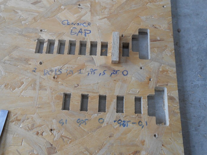
The second test
I'm quite happy about a clearance gap of 0.125 mm. So I'll use this in the big next design.
Turn an existing design parametric
Before I do my own design, I'd like to try an existing design with the 0.125mm clearance that I liked from the test.
Jonathan Minchin, our Fabmanager, is also the creator of the Open Source Bee Hive (OSBH). But the model is not parametric.
I feel adventurous and I turn the open source files available on the opensource bee hive page parametric.
You can also find the beehive as well as other sweet little kits on AKER
The files on the OSBH website are rhino files. I redo from scratch the design in SolidWorks taking measures in Rhino :
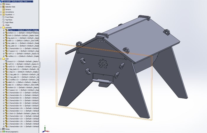
The Parametric OSBH in SolidWorks
I created a set of equations that are driving the design :
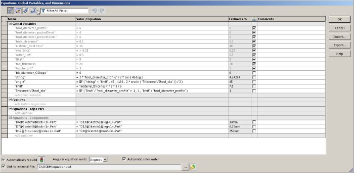
The equations
They are all linked to an external text file where I define my basic parameters :
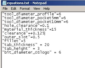
The parameter text file
This is where I define my 0.125 clerance, my material thickness, etc.
In the model it dynamically, drives the clearance :
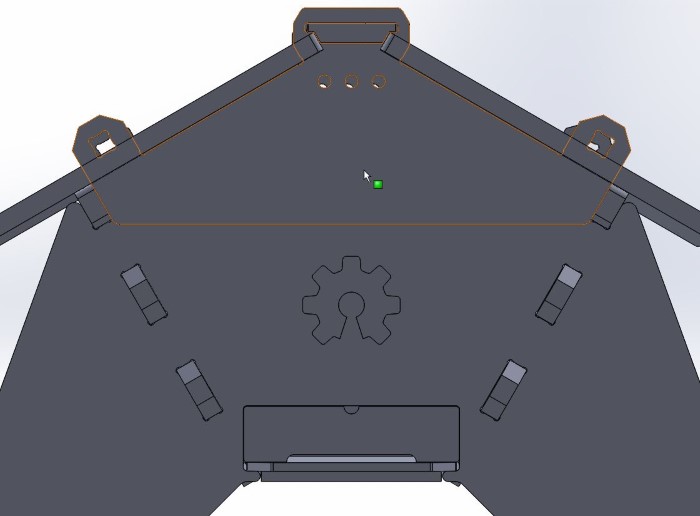
Updates in the 3Dmodel
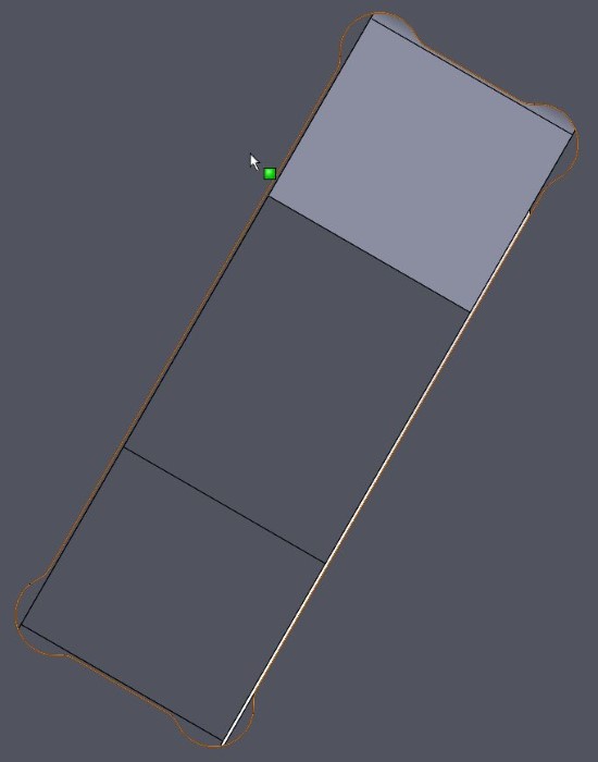
Updates in the 3Dmodel (Zoom on clearance)
Then I nest the parts. Let me point out that the nesting itself is parametric, I'd just have to change the external text file :
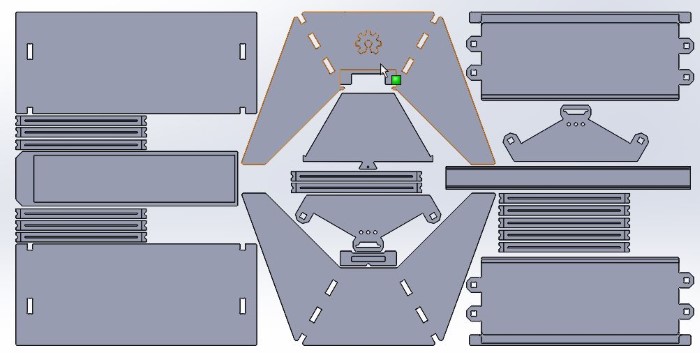
The parametric nesting
I generate sketches corresponding to the different milling strategies using the "convert" function in SolidWorks :
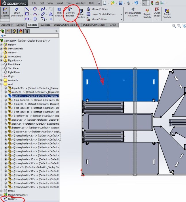
Converting the curves for milling strategies
I create a SolidWorks drawing where I have my sketches/strategies :
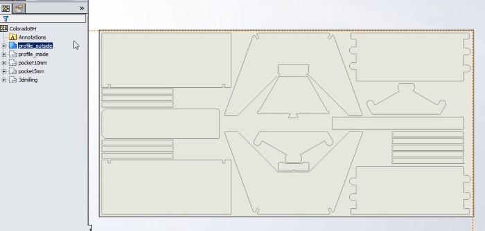
SolidWorks Drawings for each milling operation
I then just have to import them in Rhino and use RhinoCAM to generate the toolpaths as we already did for the test file :
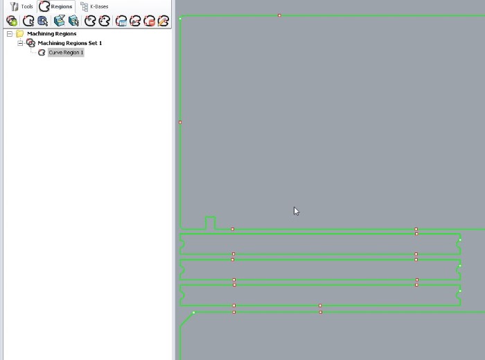
The different machine jobs in RhinoCam
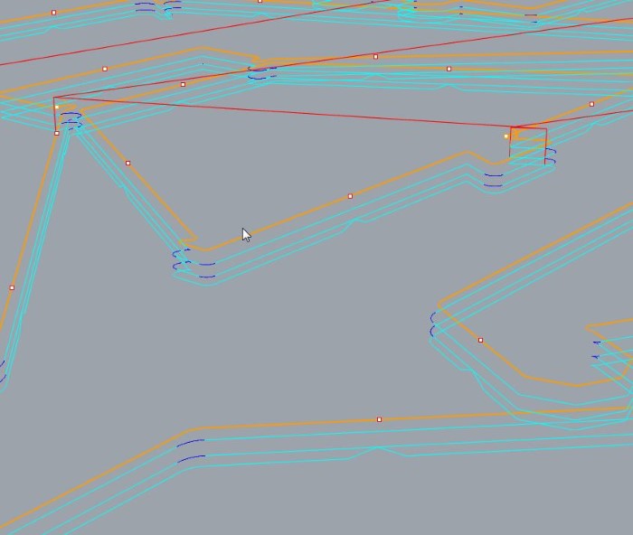
Here are my different machine operations :
The different machining jobs
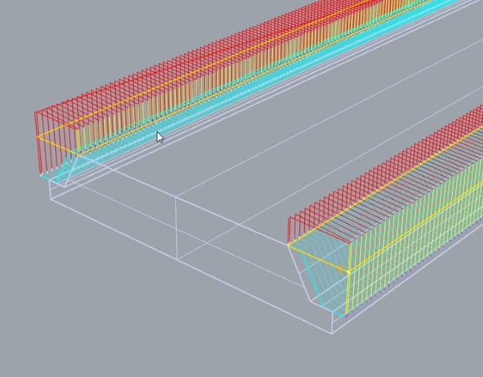
One little note : we've been told that the ShopBot likes it better when the toolpath does not contain arcs so we set up the machining to output on ly arcs:
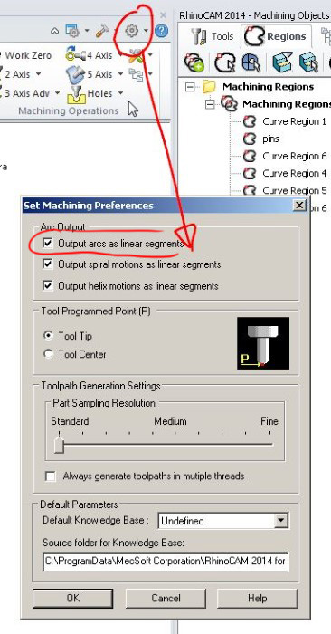
Output only arcs
Machine it and assemble it
From RhinoCAM I export my toolpath to .sbp files.
I put them on a usb stick and off I go to the woodshop where the shopbot is :

Greenfablab's shopbot
The milling goes smoothly. Job after job.
First the pindown to know where to put the screws that attach the board flat on the sacrificial board on top of the machine's table.
Then the pockets, 5mm and 10mm.
Milling of 5mm "pockets"
Then the 3D milling. This one was very long. I'm sure we can enhance the speeds, especially the Z jog speed and Z retract speed.
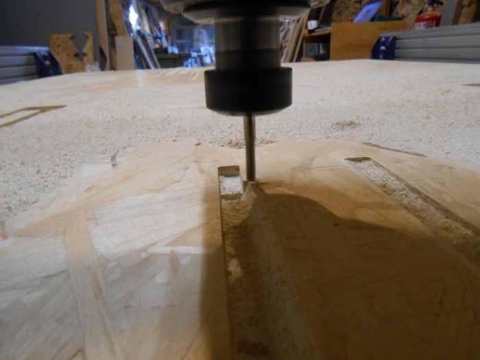
A 3D milling operation
And finally our profiling with bridges that cuts out all the parts.
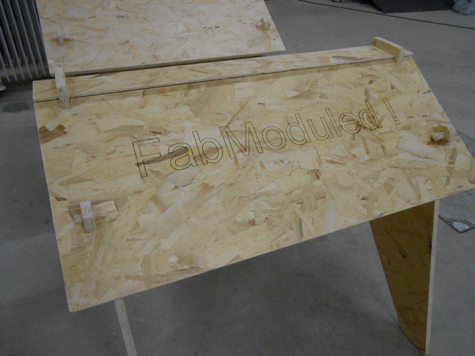
Once we've detached all the parts, here is what we have :
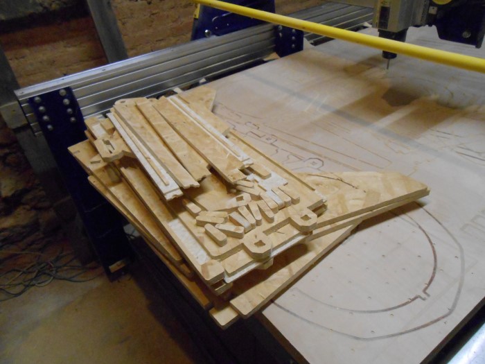
All the parts just cut out
Now comes the happy time of .. sanding!
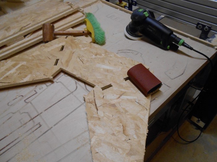
Sanding the parts
Because the mill bit I used has flutes going on ly in one direction, it cut nice on the top but not so well on the bottom
I then had to sand all those edges and also clean the tabs
I liked it it's very meditative
I found that the most efficient way for me was to rough clear the tabs with a wood chisel and then for the edges use sand paper by hand.
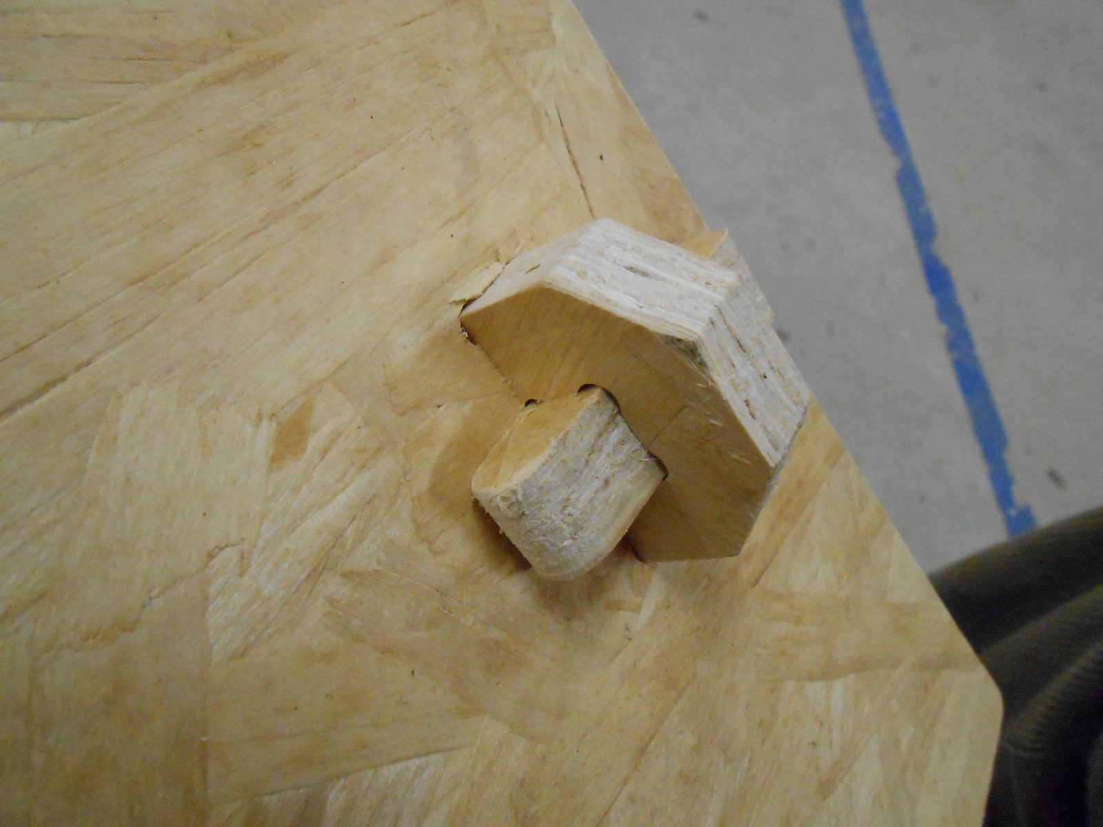
Once we're done with the sanding we feel very nervous cause the time of assembling has come and that's when we see if it's really all working together. Yeah, of course we did it in 3D before but still..
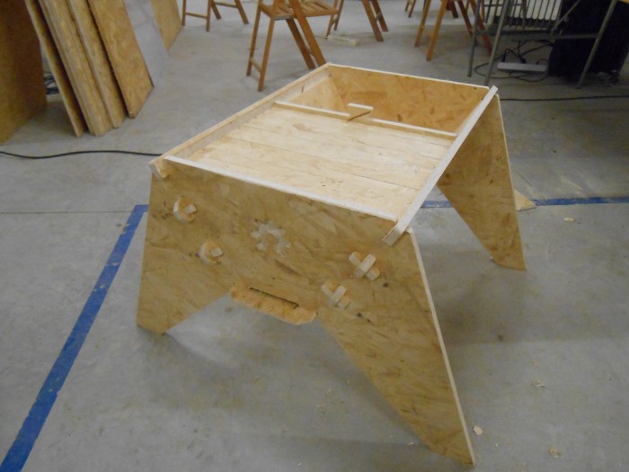
Assembling the Open Source Bee Hive
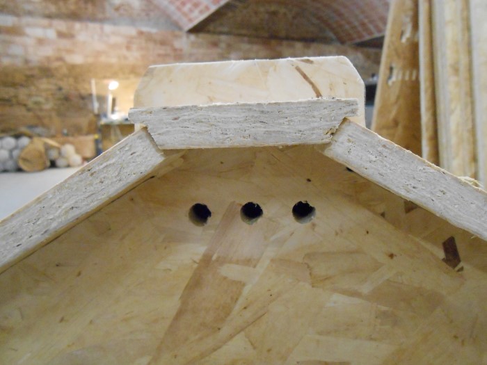
Putting the key stone... or keyWoodPiece
Fitting the last piece"
And there we go, we have an Open Source Beehive !
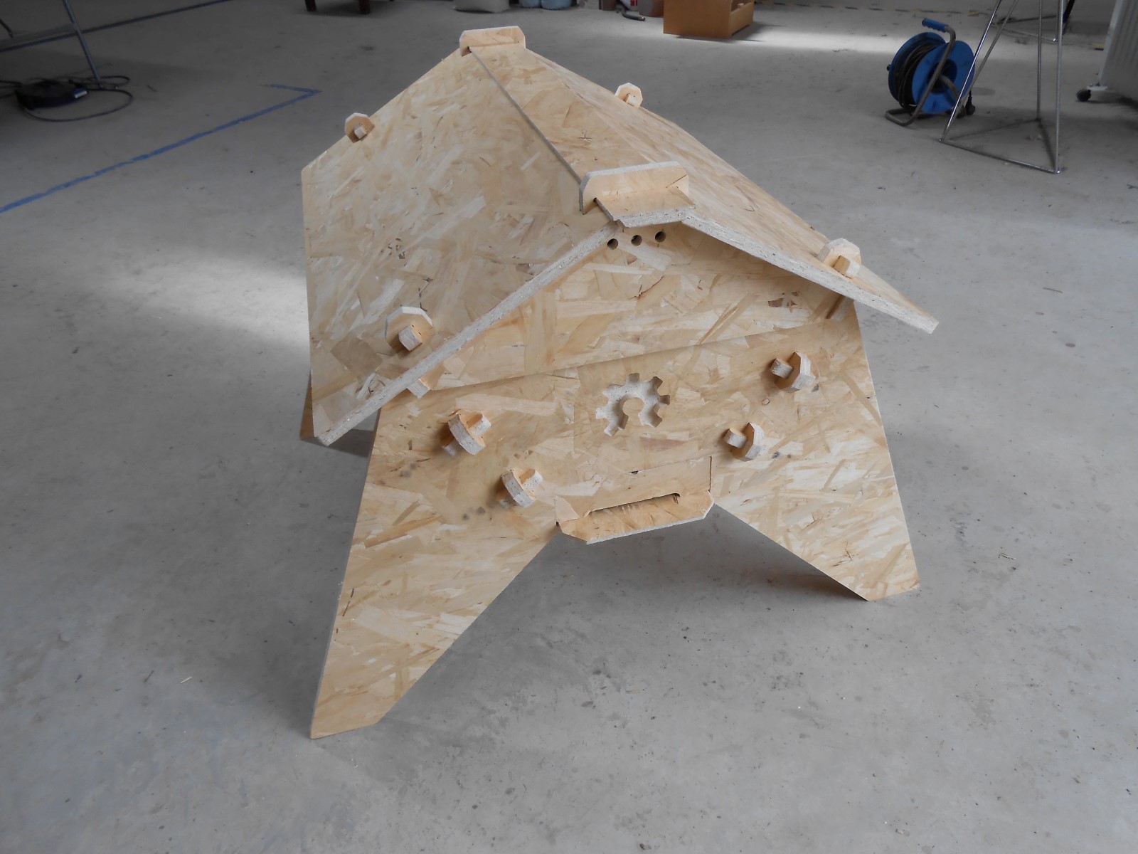
The completed OpenSourceBeeHive
some details shots :
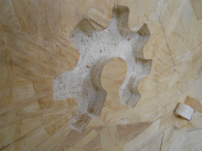
Details of the BeeHive
I noticed some minor mistakes during the assembling. I'm the one at fault. I correct very quickly in solidworks for the next beehive being milled somewhere in the world! Open source right!ç?
Also, since we're using pins to assemble the whole structure, we don't need to have the joints tight like the test we did at the beginning. So I also increase the clearance in Solidworks.
using fabmodules
I want to try the fabmodules
So I'm gonna make the same Beehive but this time using the fabmodules and not RhinoCAM
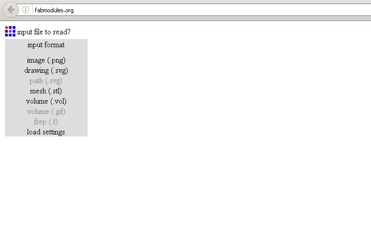
The fabmodules Website
That means that I need to generate and feed the fabmodules website a set of PNGs that it can digest.
We'll explore the process of doing this from Solidworks.
First rise the question of the PNG resolution.
Indeed, let's say we want to be accurate by 1/10th of a millimeter, which is not very accurate since it's almost the clearance we wanted in the previous test.
1/10th of a mm accuracy means 10 points per mm so 254 points per inch, 245 DPI.
Since we have a piece of plywood that measures 2440x1220 mm,
we need to generate a PNG that's (2440x10) x (1220x10) = 24400x12200 pixels!
That's a big png ! And computer ressources might lack.
I'm lucky enough to have a decent amount of memory on my computer so that's not an issue. But something else became an issue, which is the size of the PNGs the fabmodules can take, and it looks like there is a limit below this.
I do not know what is the limit but, having tried a whole span of different DPI values it looks like it's around 72dpi for a full plywood sheet.
Values above give no result or weird behaviors such as :
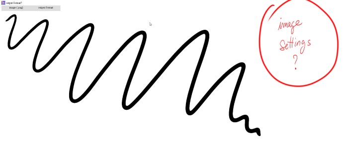
Bug when DPI slightly too high
Well, with 72 dpi we get 72/25.4 = 2,83
so a little less than 4 points per mm which is not accurate at all.
But I still want to try to cut the updated OpenSource BeeHive with the gcode generated by fabmodules.
Alright, so I need to generate from my design in Solidworks a set of PNGs that represent my different machining jobs.
In order to do this I create extra volumes based on the nesting that define the machining regions (these are not necessarily the actual parts contour).
And from these solidworks parts I create solidworks drawings with the right viewing mode "shaded with no edges" :
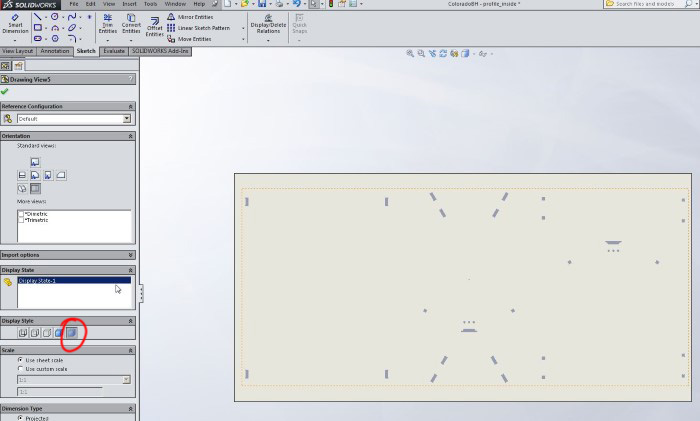
Ex : Volume for inside profiling
Then I export the drawings to PNGs with black and white option.
And since we found out previously that 72 dpi was our limit, we set this up as well and also the dimension of our sheet :
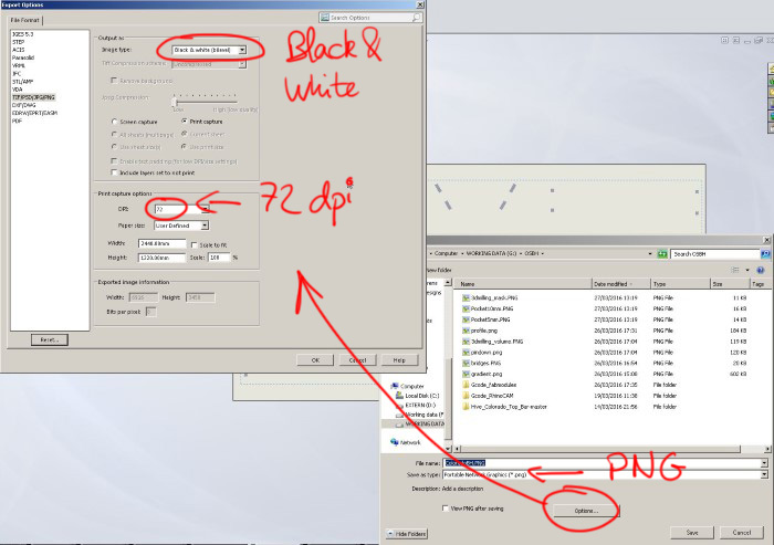
Exporting to Black and white PNG
The 3D milling job requires a litlle bit more explanation
The idea is to encode depth with grey values right?
Well then the trick is to assign a black to white gradient as appearance on the side of the part :
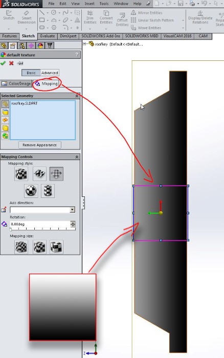
Gradient mapping for Depth encoding
We don't have to be super accurate with the position of the map, we'll fine tune this in a image editor later.
I also found out that we have to get rid of all the other lights other than the ambiant one :
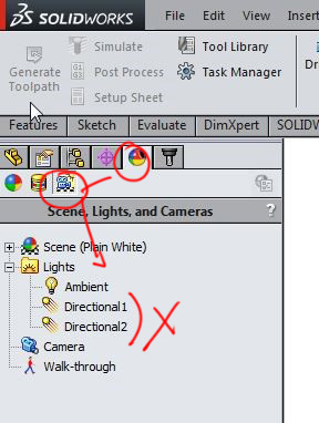
Deleting the superfluous lights
And that we also have to get rid of the default background :
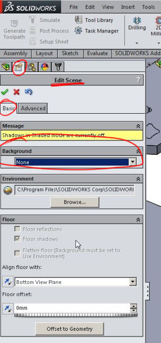
Removing any background
Lastly, for this export we choose "grey scale" :
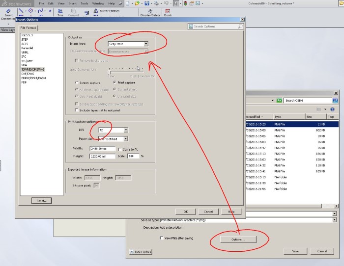
Export with greyscale option
Then we have a little bit of work in Photoshop, like setting up the right grey values for the 3d milling :
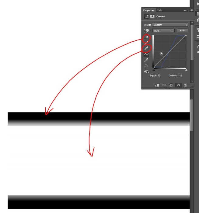
Setting the right grey gradient
and also setting up the right grey values for the bridges :
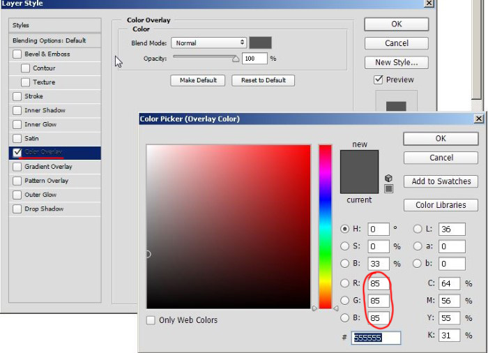
Setting the right grey value for the bridges
Lastly, since I'm gonna use the "foam rough cut" option in fabmodules to generate my bridges, I use the expand selection tool in Photoshop to create only a black area that represents the profiling, letting the fabmodules algorithm figure out where to go inside and generate bridges :
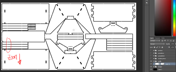
Creating the profiling cut
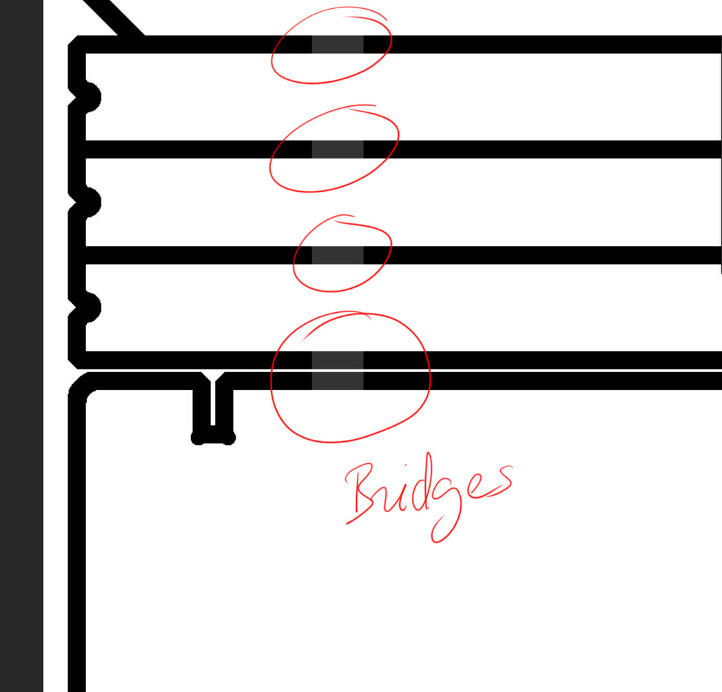
Zoom on bridges
So, now that we have our set of PNGs, we can run the fabmodules for each of our job (click to enlarge and see parameters) :
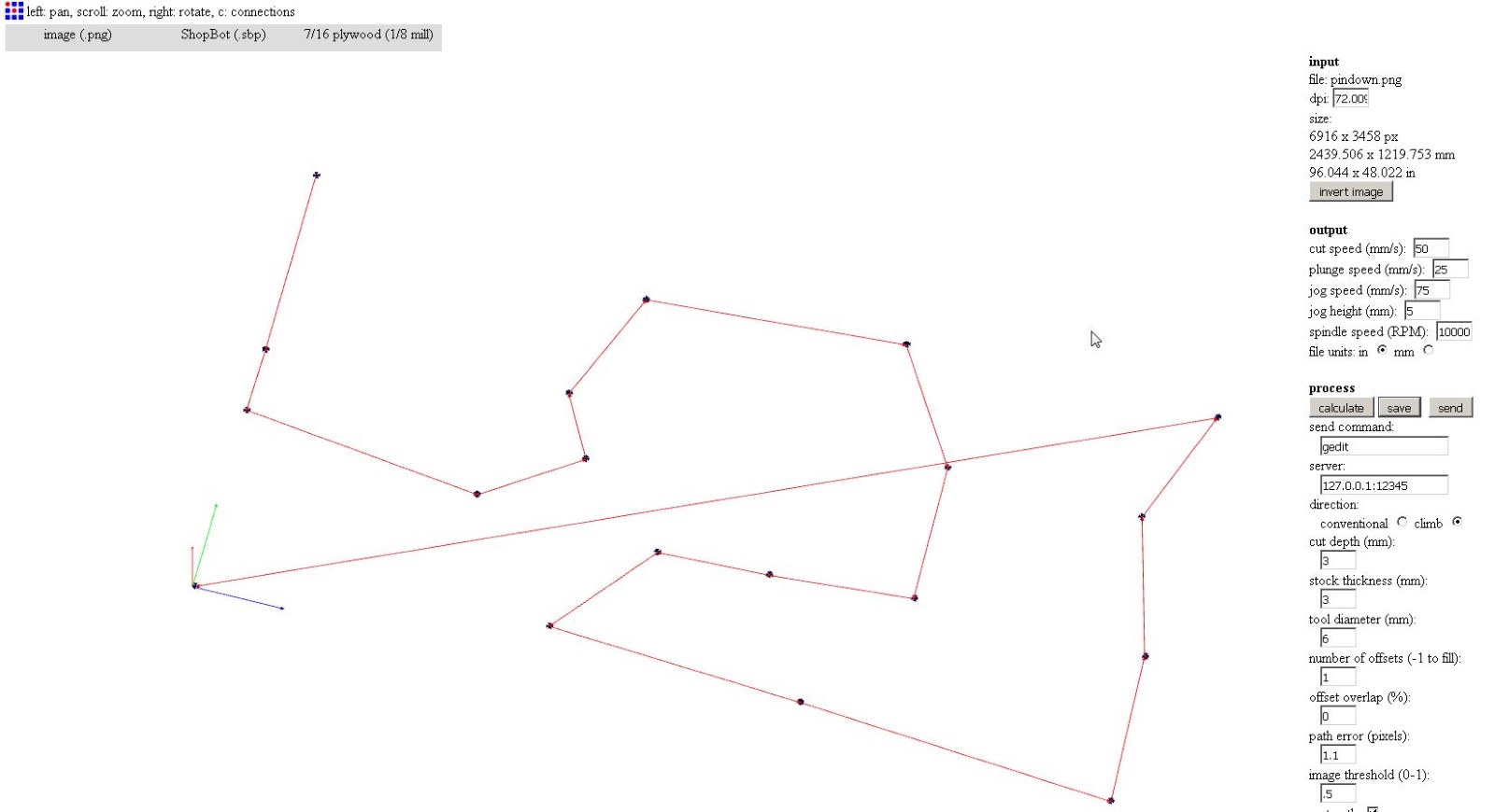
PinDown job
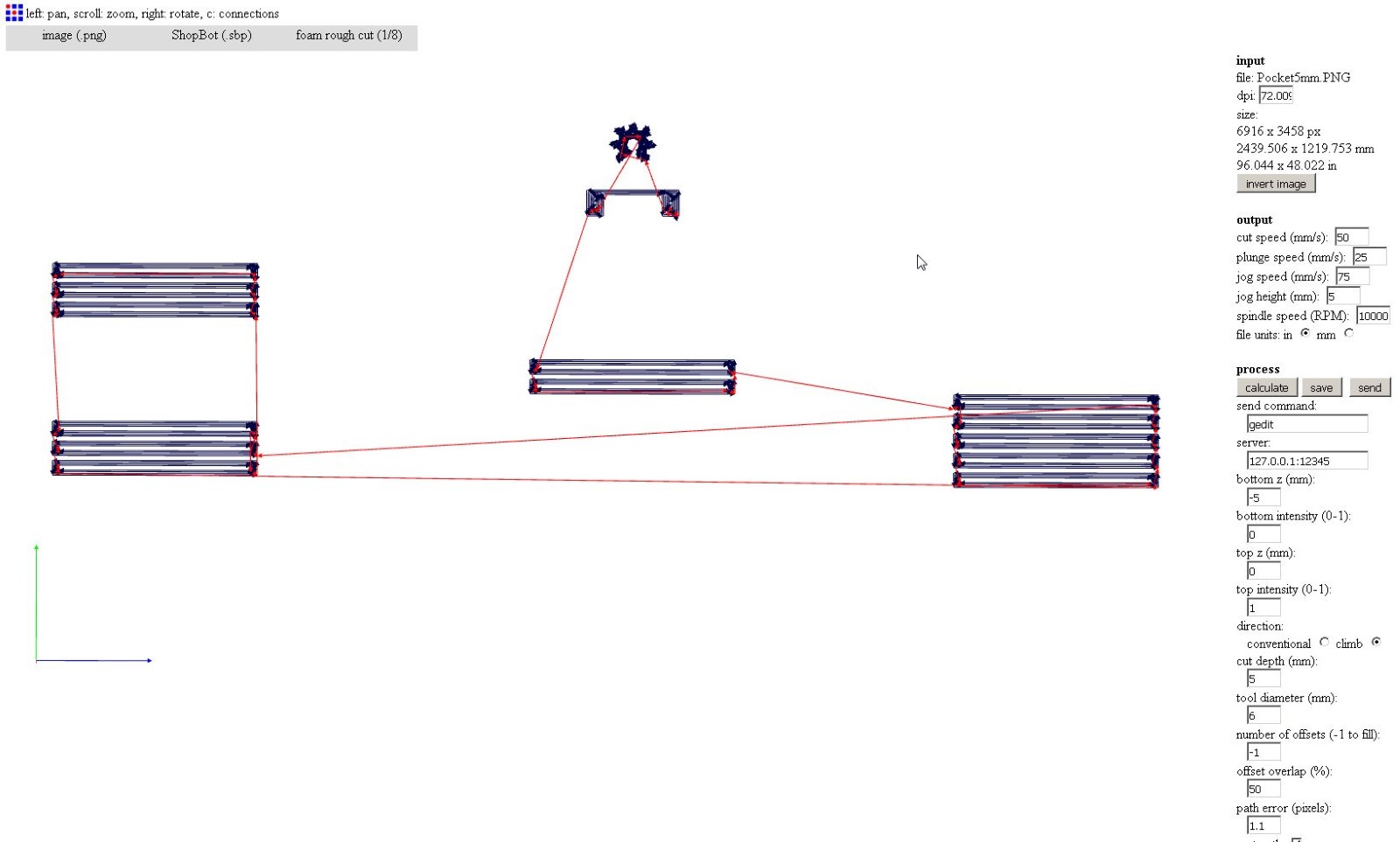
Pocketting 5mm
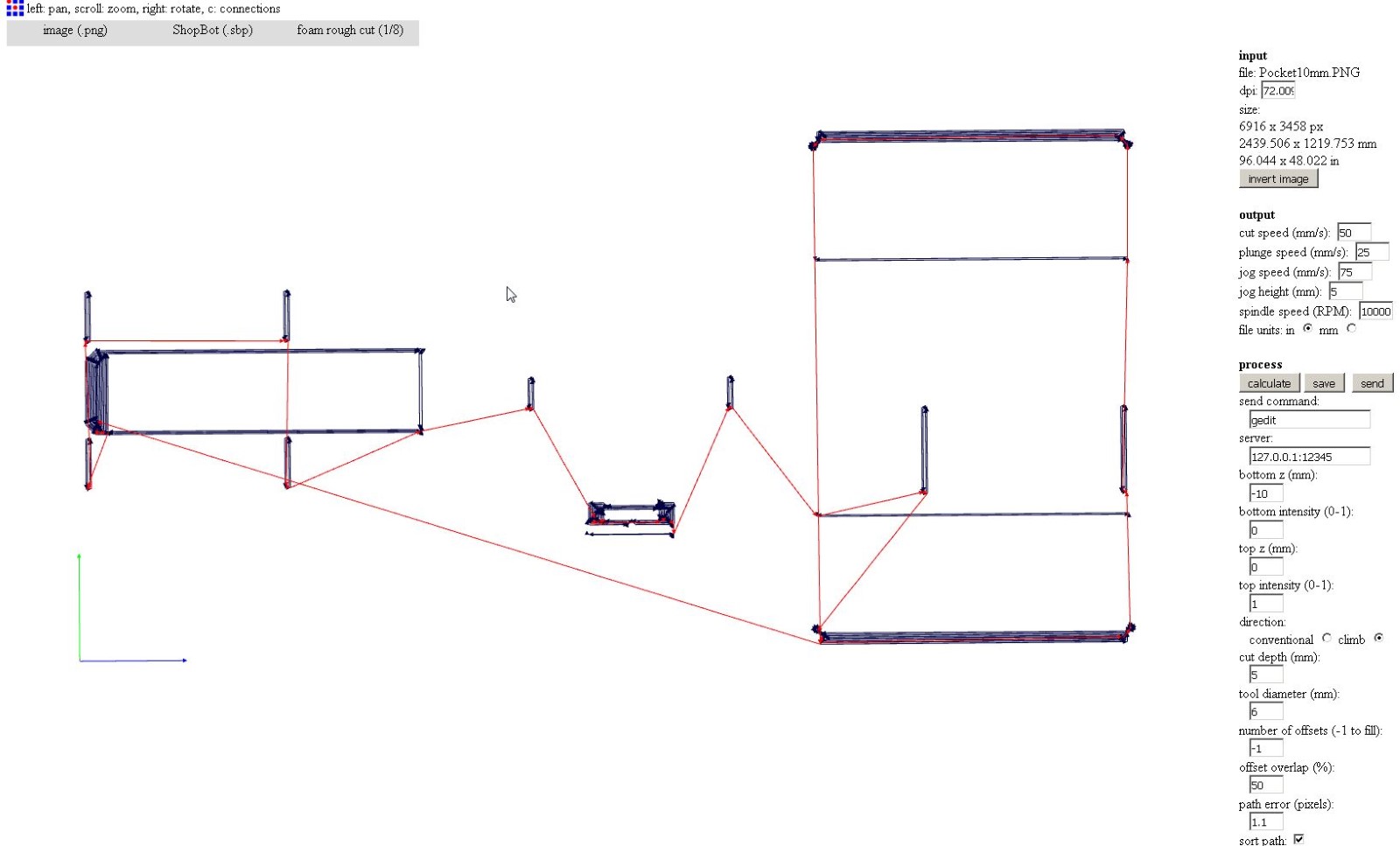
Pocketting 10mm
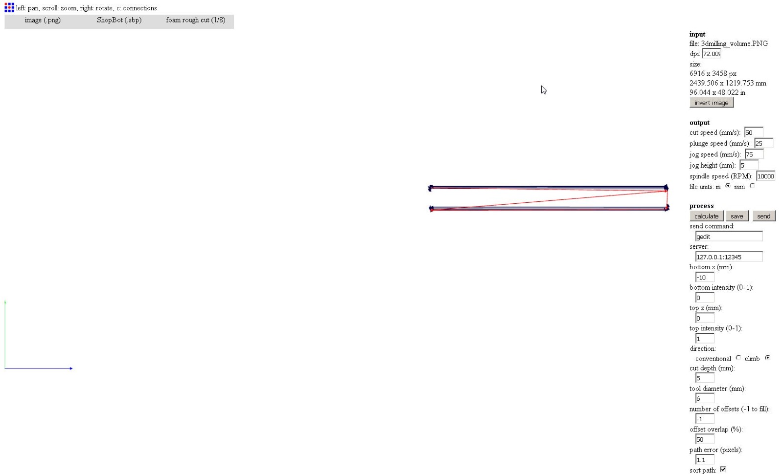
rough 3D milling
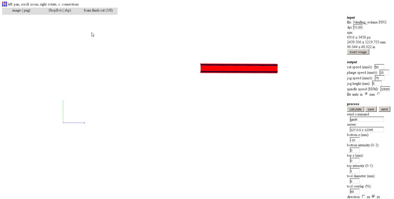
Fine 3D milling
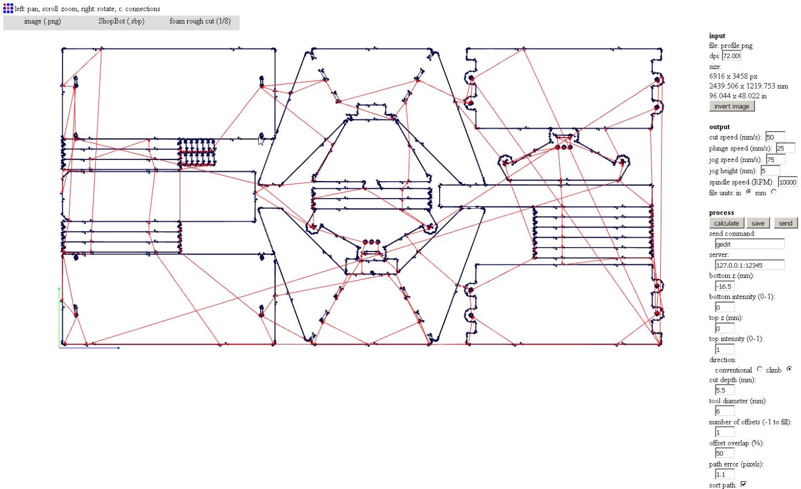
Profiling
Bridges generated in fabmodules
It's nice to have the bridges generated parametrically in Solidworks and just have to export them cause setting them up where we want is usually a pain.
We can for example always have a bridge in the middle of an edge, no matter how the part is changing.
Off we go now again to the shopbot.
One thing I noticed is that the shopbot slows down a lot in areas where there is a lot of little movements, typically round cuts.
We can observe this in the next video :
Slowing down in tiny round parts of the cut
I don't really like this for two reasons: First, it's making the machining time much longer and second it can potentially overheat the mill bit.
I'd have to try that later but I think we might be able to overcome this by playing with the way the shopbot approximates the toolpath and handles the stopping at every end of instructions.
Another step along the milling process, the 3d milling to do the angled slope :
3d milling generated by fabmodules with a gradient.
And after few hours of milling and sanding :
The OSBH by fabmodules
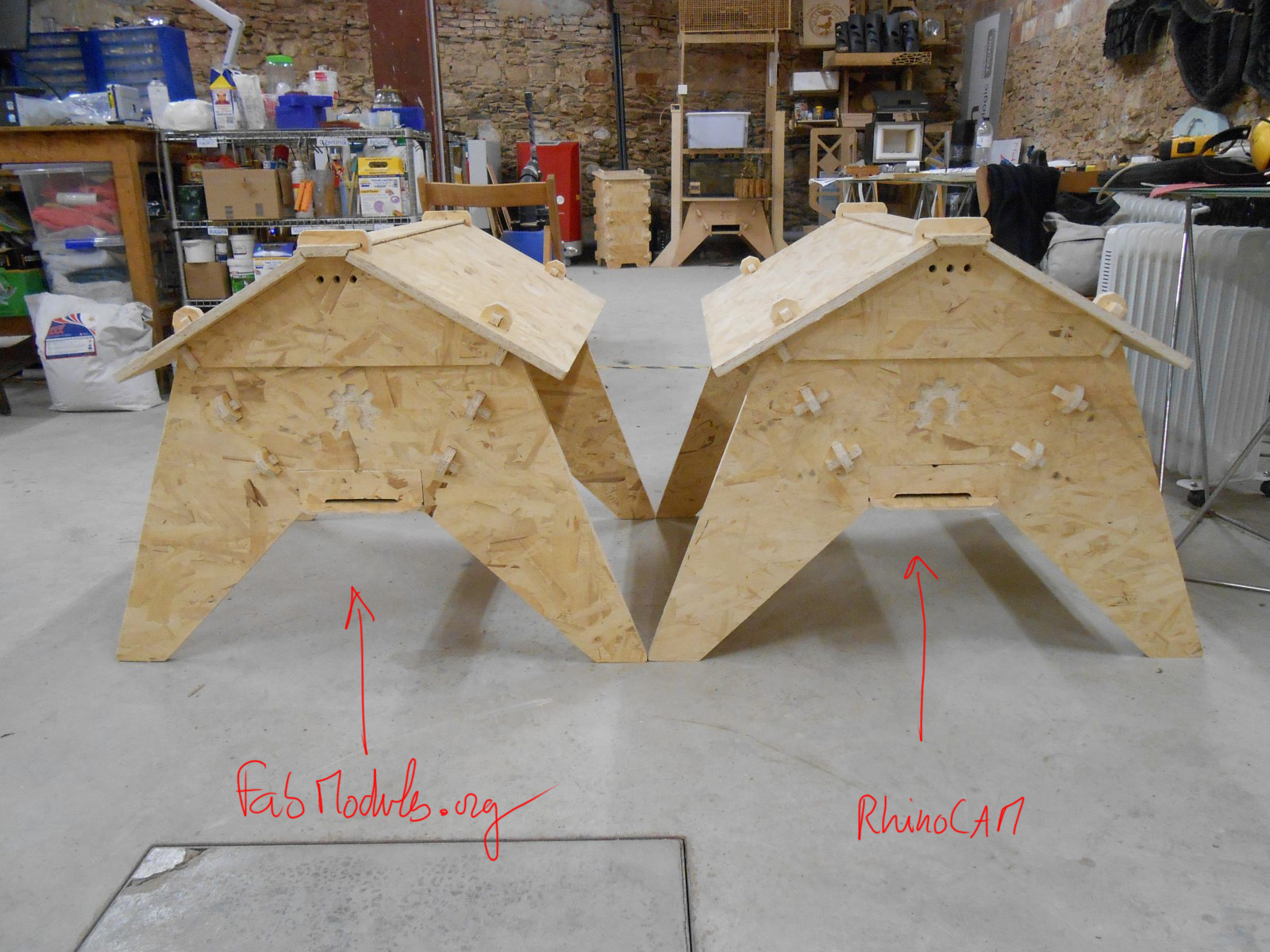
The two OSBHs
I find that fabmodules, despite the accuracy limitation works suprinsingly good. I could still see a difference when I assembled it.
For example, the dogbones are not as nice as the one done with RhinoCAm :
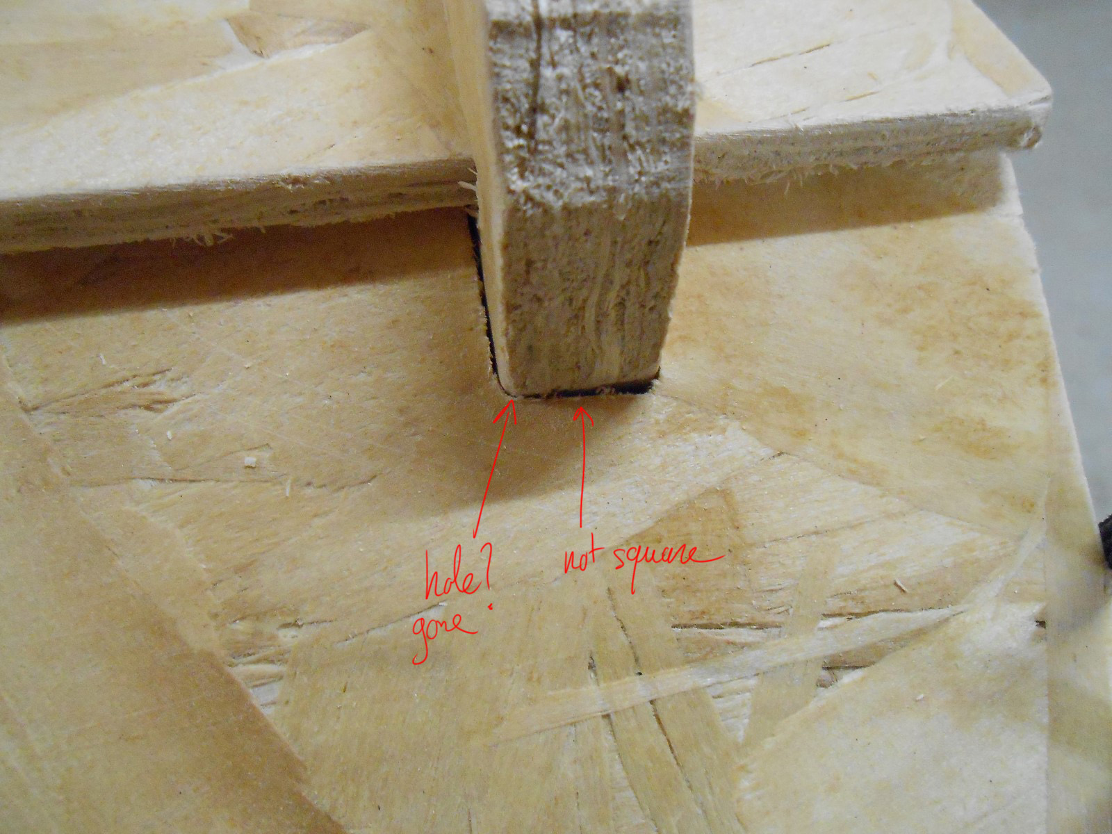
DogBone with fabmodules
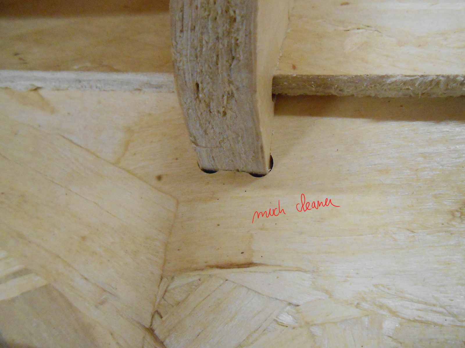
DogBone with RhinoCAM
But in the end, it doesn't matter so much when we have a design that's forgiving like ones with pins, cause the tightness is acheived in another way than having tight cuts
What's really important to notice though, I think, is that anywhere in the world where we have an internet connection, we can generate a gcode from pictures. That is a huge step in openhardwaring and adresses, to me, a big issue : the technological and knowledge gap that there is from one to an object.
If we really want to do a revolution, then it has to be very accessible to anybody.
What would be optimum is to have a parametric gcode : an online tool that turns few parameters of an object in a text file or an online form (such as the thickness of the wood or the bit size) into the right gcode for us
I think antimony and fabmodules could run in tandem as services on a server and do that.
I'd be glad to help with this but I ain't got so much time nor programming skills.
I'm still going to play around with that idea with VisualMill for Solidworks...
Using VisualMill for Solidworks
I downloaded the demo of VisualMill for Solidworks.
VisualMill for Solidworks is pretty much the exact same plugin that RhinoCAM is for Rhino, from the same company.
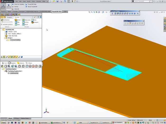
VisualMill in Solidworks
I find that it's much more stable in Solidworks though.
It's also nice not to have to export our whole design from Solidworks to Rhino just to generate a gcode, we stay in the same software.
But the very interesting thing is that we pretty much get a PARAMETRIC GCODE!.
Demonstration with this video :
New gcode only few clicks away from new parameters.
So if the fabfoundation wants to do some "social engineering" with Mecsoft to have this tool for free in fablabs, that'd be welcome!
And since Solidworks is already a partner, that kinda makes sense.
Make my own design
I sketch on the paper my own design :
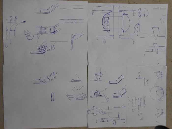
Paper sketches of my own design - A press-fit green house system
This is a press-fit greenhouse structure :
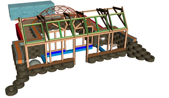
3D view of existing greenhouse structure Earthship Biotecture uses
This one is still cooking
Source files
Here are the sources files of the projects I talked about on this page :
Grasshopper clearance finder test file
The Rhino file with test cut RhinoCAM machining jobs
All the files relevant to Open Source Bee Hive
Conclusion
***