Week 4
Electronics Production
Assignment
- make an "in-circuit programmer"
Week workflow
Here is how I see the week's flow :

Flow chart for this week
Understanding the context
Before going ahead and make our week assignment I wanted to know a little more about what we are doing.
I found this post on AVRFreaks.net very enlightning.
I also find this simple diagram helpful to understand the context :
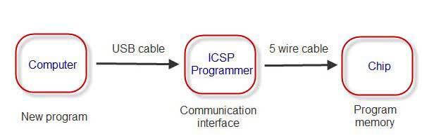
Diagram of the ISP programming method
ISP stands for In circuit Serial Programming. The idea is to program microcontrollers (the chip) already soldered on its circuitry through a connection called serial port.
So in our case, once we'll have our board made and populated, we'll use a programmer, which is also a microcontroller that has been programmed to be a programmer, to program our FabISP to also be a programmer, so that it can , in turn program other chip, get it?
It's a little bit like the FAbacademy : we need a fabmanager to explain us how to be fabmanagers in order for us to become fabmanagers to teach others.
Using ISP method of programming, we can't program our FAbIsp straight from usb, it won't understand it. We have to first program our future programmer through serial MISO MOSI port.
Table of content :
STEPS
Generating tool path
I first download the FabISP files on the fabacademy class :
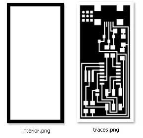
FabISP files representing the traces and the outline
I modified them a little bit by editing the PNG just for fun. Nothing very complicated. I just changed the shape of the traces :
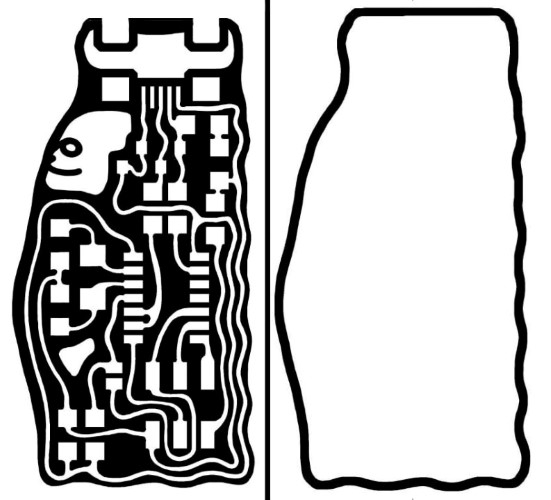
FabISP files representing the traces and the outline
I then used the fabmodules.org website to calculate the toolpath.
Since we are using a Roland Modela MDX-20 with 1/64" and 1/32" bit we select the right parameters :
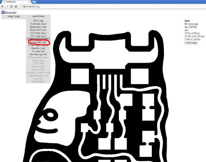
"Roland" machine family
"Traces" kind of tooling
Calculating the toolpath.
And here is what we get :
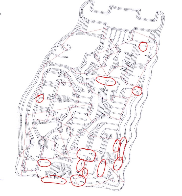
Toolpath generated - some traces merge
we can see that some traces are merging. I've circle them in red.
I retouched my traces PNG image and I get it right :
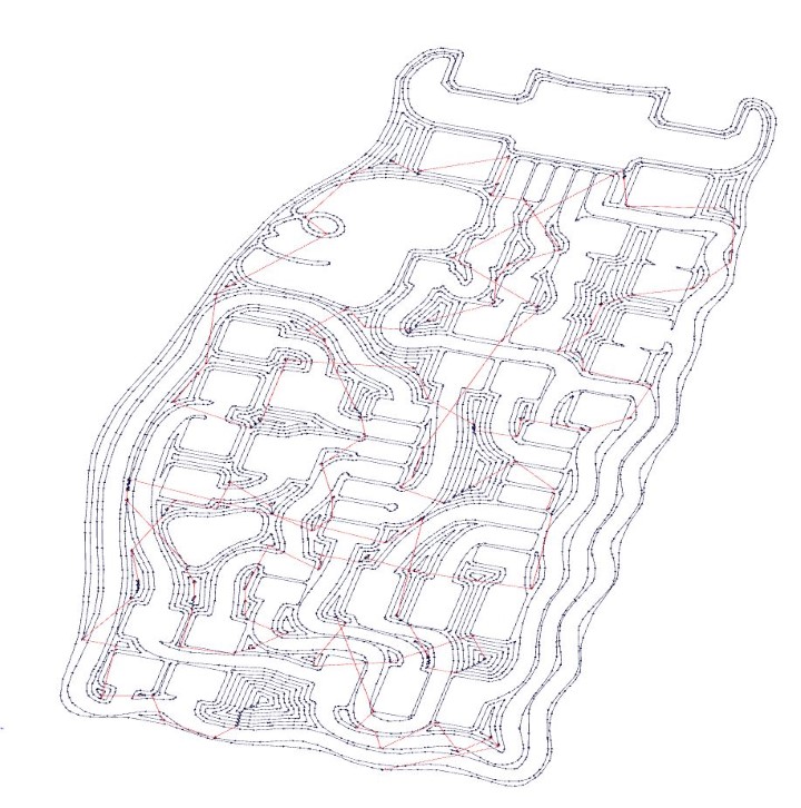
Traces are OK now
One trick I found is to use the image thresold parameter after having put some feather effect on the edge of my traces. That gives control over the size of the traces in fabmodules :
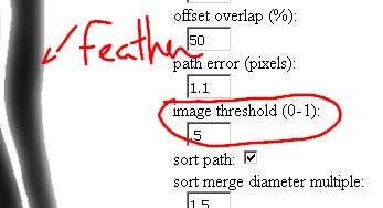
Feather and image threshold parameter
I have now a .rml file that the Roland machine can read.
Actually, after I generated the file, I found out that the Roland modela we have can only run from the fabmodules "fab" installed locally on the machine hooked up to the modela.
I just then transferred my PNG on this computer and run again the fab process locally which drives the machine.
Milling the board
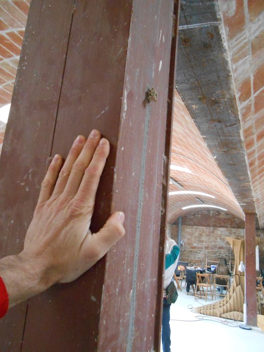
"We take a FR1 board (board with copper on top) and we make sure it's flat :
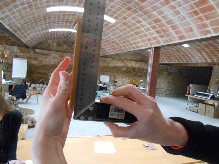
Checking the flatness of the board
It was not perfectly flat so we bend it gently with our hands. (Thanks Marcell for your bending hands)
We then apply some double sided tape on the bottom of the FR1 sheet. This is to hold it tight while we mill the copper on top.
Using something like a plastic card is useful to avoid making air bubble which would set the FR1 sheet out of level (Not good).
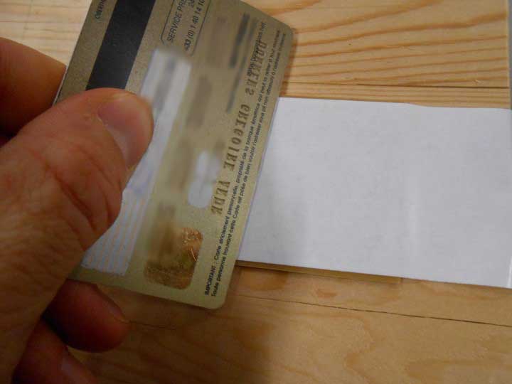
Sticking some double sided tape
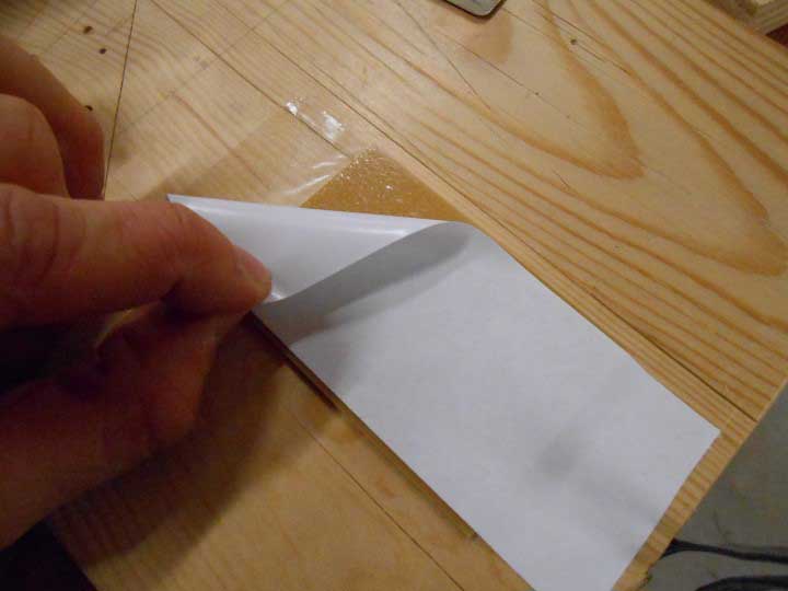
Removing the bottom layer
We then put our board on the top of the Modela's sacrificial sheet.
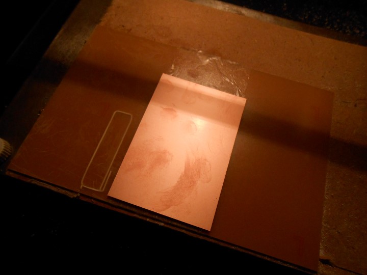
FR1 sheet in place on the sacrificial sheet
We can see there is a lot of fingerprints. We clean them with alcohol and a brush.
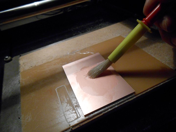
Cleaning the FR1 sheet
And here we go, we launch the milling from the fab software :
Milling around the traces with the 1/64" bit
I had to do a second pass with the "cut depth (mm)" parameter set to 0.2 cause on one side of the board the copper was not totally milled due to a non perfect level situation.
I didn't abort my first 0.1 pass cause cutting too much at one in the "high" area could potentially break the bit.
After about 5 minutes of milling : Here is the result.
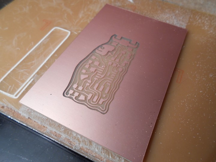
Traces
Now we have to cut the board. It's a different operation that we set up in the fab software. Basically it changes the cut depth.
We'll have our FR1 board cut in 3 paths.
We use a bigger bit : 1/32"
Milling (cutting) the outline with the 1/64" bit
We can now untape everything and get our freshly milled board!
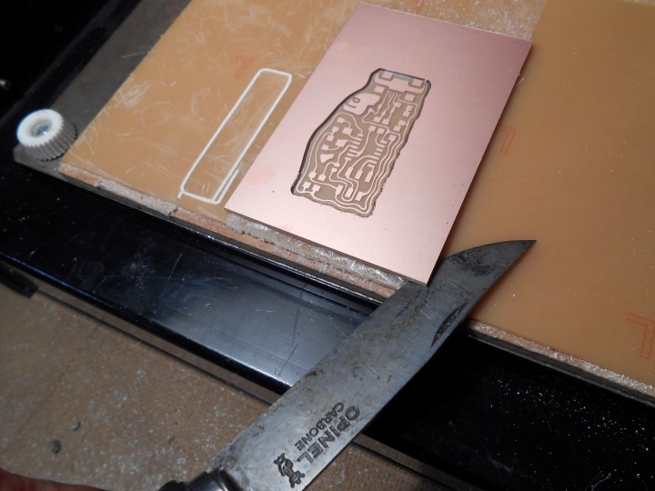
Removing the board from the sacrificial sheet
FabISP Modelling Shot :
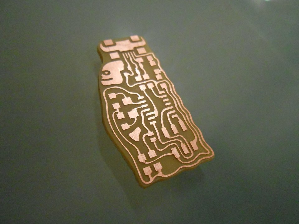
The FABIsp board Board unpopulated
Now we've earned the right to populate the board!
Soldering
We have the chance to have very big metal beams in the Greenfablab. To limit the risk of static electricity killing the microcontroller I'll discharge myself before manipulating it.
Removing Static electricity from my body
Then I solder the components one by one. Taking them, also one by one to not make a mess, from these nifty little drawers :
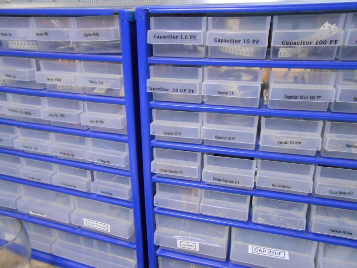
Components drawers
Honestly, I find that soldering is behaving exactly like water when it's in liquid state. That helps getting a "feel" of how it works.
To continue this metaphor, the flux is like the soap, it helps to "wet" the surface we want to put water on.
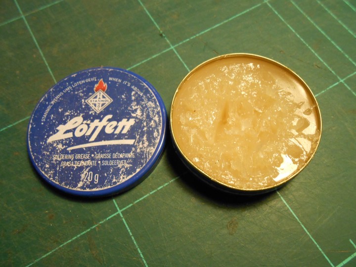
Flux
With a cue tip, I then put soldering on the pads where the t44 (our microcontroller) goes.
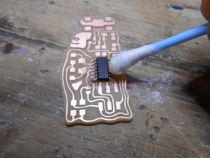
Puting flux on the t44 pads
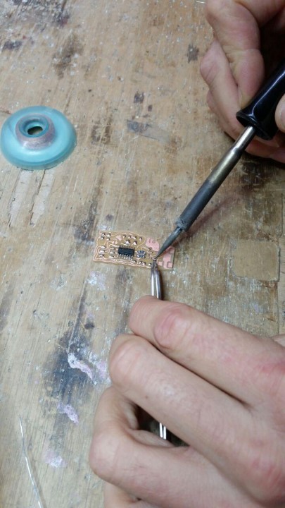
I then solder two opposite corner pins maintaining pressure with tweezers to hold the chip making sure it's perfectly aligned.
After that, I don't need to hold it anymore and I solder the other pins by almost just touching them with a "solder wet" iron tip
I do this for the other components :
Soldering the components
And here is the populated board !
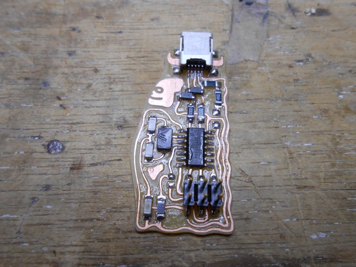
Board with all the components
A little bit of cleaning...
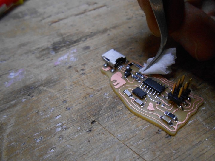
Cleaning the board with alcohol and a little bit of tissue
Again, model shot of my board :)

ISP Programmer Vogue magazine
Testing and programming the ISP board
First test : we plug the board in the computer through usb...
No smoke... No power drainage signal on the computer... Good!
The next step is to connect our board to a programmer, which is an interface between the computer and our chip.
Here is my understanding of the whole workflow :

ISP Programmer Vogue magazine
In our case, the interface is another microcontroller (commercial one) named AVRisp mkII :

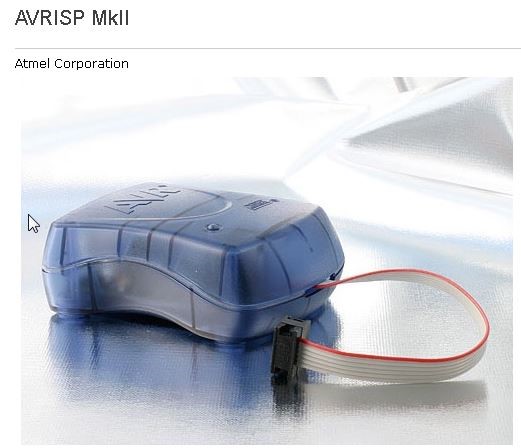
AVRisp mk2
I was curious about this "AVR" that we see everywhere. Turns out to be named after the two inventors of the AVR architecture, two students, Alf-Egil Bogen and Vegard Wollan : Alf and Vegard RISC processor. (Wikipedia).
At this stage, I'm running Windows. I need to install the drivers for the AVRisp mk2.
I first try to install the drivers the fabacademy tutorial links to, on the adafruit website. They don't work.
After some internet searching, I find them on SourceForge
I install them and the AVRisp is recognized in the Device manager:
Here is my understanding of the whole workflow :
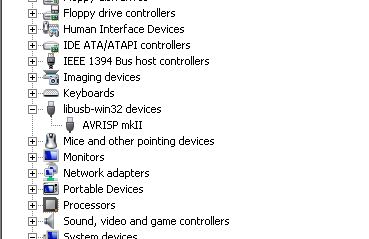
AVRisp mkII recognized
After that, I download AVRdude and try to communicate with my ISP board through the mk2
I first need to power via usb my ISP and connect it to the AVRisp with a 6 wire ribbon as follows :
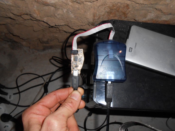
Connections to program the ISP
The led is not green. It seems to be blinking orange :
LED blinking orange
What does that mean?
Also, when I try to communicate with the ISP, the LED turns green.
Based on the makefile provided for the FabISP firmware, I typed :
avrdude -p t44 -P usb -c avrisp2
-p t44 means we want to program a attiny44
-c avrisp2 means that for this we are using a avrisp mk2
-P means we're doing this through usb
But it also tells me that it's not working :
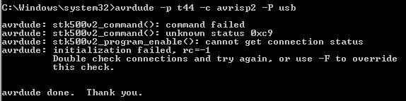
Error when trying to communicate
So what's going on with this blinking orange light ?
I check the documentation on the Atmel website :
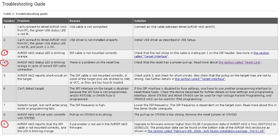
Atmel documentation
So there is three potential causes :
- Problem with wiring
- Problem with RESET pin on chip
- Problem with AVRisp mkII firmware
I check the connection, the soldering around the connection using a multimeter. Everything is fine. It's not 1.
I check the datasheet of the t44 :
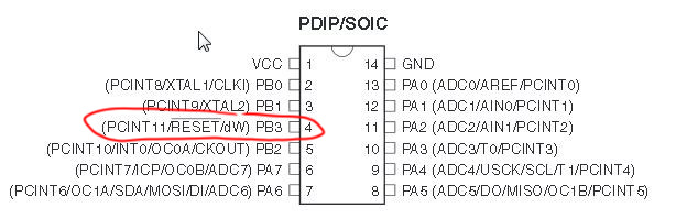
Connections to program the ISP
It's pin 4. I check the connection and the soldering again with the multimeter. Everything seems ok.
hmmmmm... So it's 3. ?
The troubleshooting documentation says to upgrade the AVRisp firmware because it might corrupt or too old.
And it says that to do this we need to open the avrisp2 and shunt two pins !
I check the date of manufacturing as the advise us to do :
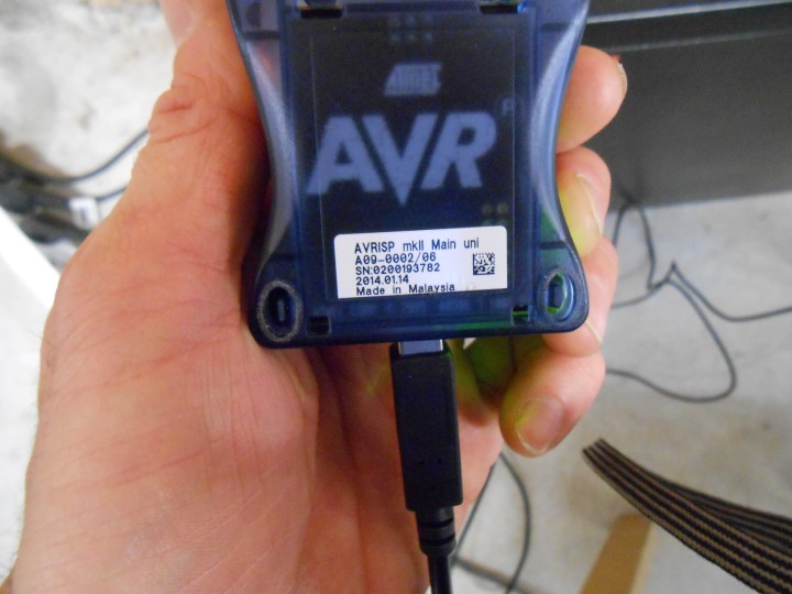
Date of manufacturing : 2014
Not so old! (we are in 2016)
Alright, so I still decide to download atmel studio and do this just to eliminate that possibility.
In the meantime, I open the avrisp :
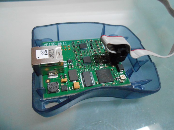
AVRisp Opened
Here we are in Atmel studio :
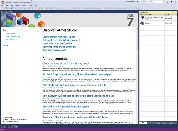
Atmel documentation
At the top right corner I right click and upgrade :
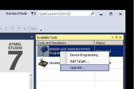
Upgrading the AVRisp mkII
Thanks to the soldering pliers, I shortcut the pins as said on the atmel doc. And I click on "upgrade":
Flashing the AVRisp mkII
Atmel studio tells me that the firmware of the AVRisp is now V1.8 and that it was before V1.7
I'm happy and I feel I fixed the issue.
Well that would be underestimating our good friend Murphy
I still have that blinking orange LED and I can't communicate with the FabISP.
Then I notice from the pin layout on the AVRisp board that the ribbon is inverted!!
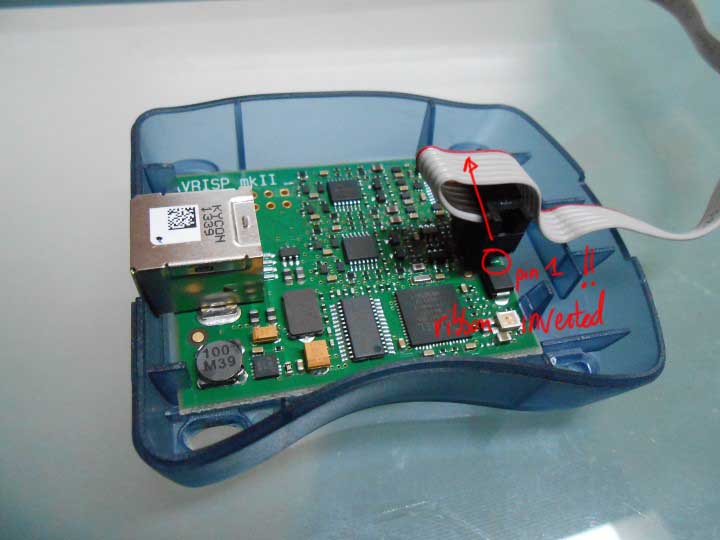
AVRisp Opened
I try again, still not working
I'm an Angstrom close to give up
I have the idea of taking benefit of Atmel Studio and play with it to see if I can't find anything.
And I find something...
If we begin a new project and try to communicate with our FabISP through Atmel Studio and not AVRdude we can have a little more info :
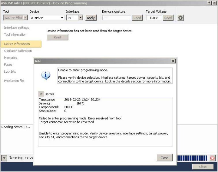
Atmel Programming mode error
I also notice this :
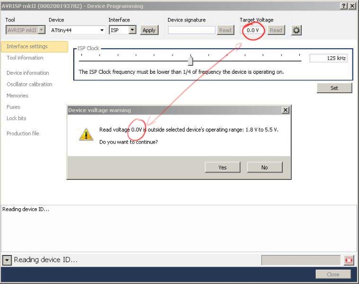
Atmel displaying a Voltage error on the target
So it seems that there is a voltage error on my board !
I check the voltage on the pin1 of my 6-pin header. No Voltage !! Should be around 5V
I quickly see that it's coming from the 0 Ohm resistor that we are suppose to remove later !
I re-solder it then.
And I get a nice reading with Atmel Studio :
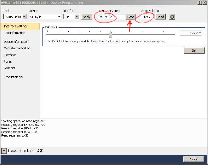
Atmel displaying a Voltage error on the target
I feel full of confidence again :)
Now that we can communicate with the FabISP chip, I decide to try to upload the program on it
Grrr... I find out that installing Atmel Studio screws up the drivers that AVRdude is using.
I decide to use linux.
I need to install Avrdude and gcc (the compiler) and all the dependencies. I then type in a terminal:
sudo apt-get install flex byacc bison gcc libusb-dev avrdude
sudo apt-get install gcc-avr
sudo apt-get install avr-libc
and lastly
sudo apt-get install libc6-dev
After that, and after downloading the FabISP firmware source code I clean and make the hex file from it by typing :
make hex
and that's where we see if it's really working, I try to set the fuse :
make fuse
Boom ! it works !!
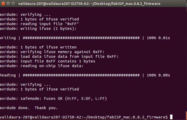
Fuses written successfully
I then program the chip :
make program
Re-Boom ! Works too :)
Now my FabISP should be recognized in the usb system...
lsusb
Ahh! it's not.... What's happening ?
Hours of debugging just to find out how stupid we were.
The usb cable we use is a fake usb cable, it is actually just a powering cable for the FabISP when we program it. It doesn't have the other data wires.
That made me very angry...
Cable punition (it's still working)
Using a proper cable got it working :
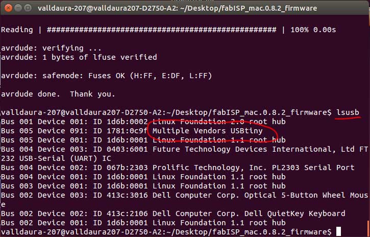
Usbtiny (FabISP) recognized
We can now unsolder the shunts :
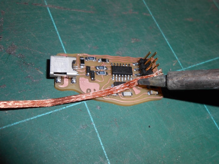
Unsoldering the shunts using braid
Now let's try something craaaazy. Let's program a FabISP with an already programmed FabISP !
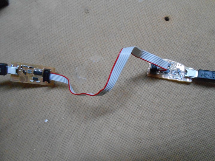
Programming a FabISP with a FabISP
To do so, we need to change the Makefile :
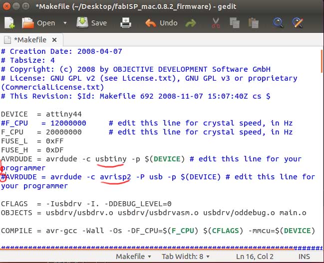
Uncommenting/Commenting the device lines
And then again
Make Hex
Make fuse
Make program
Bim ! worked too
Nice try Murphy...
Conclusion
We only learn with failure
***