Week 13
output devices
Assignment
- Add an output device to a microcontroller board you've designed and program it to do something
Week workflow
Here is how I see the week's flow :
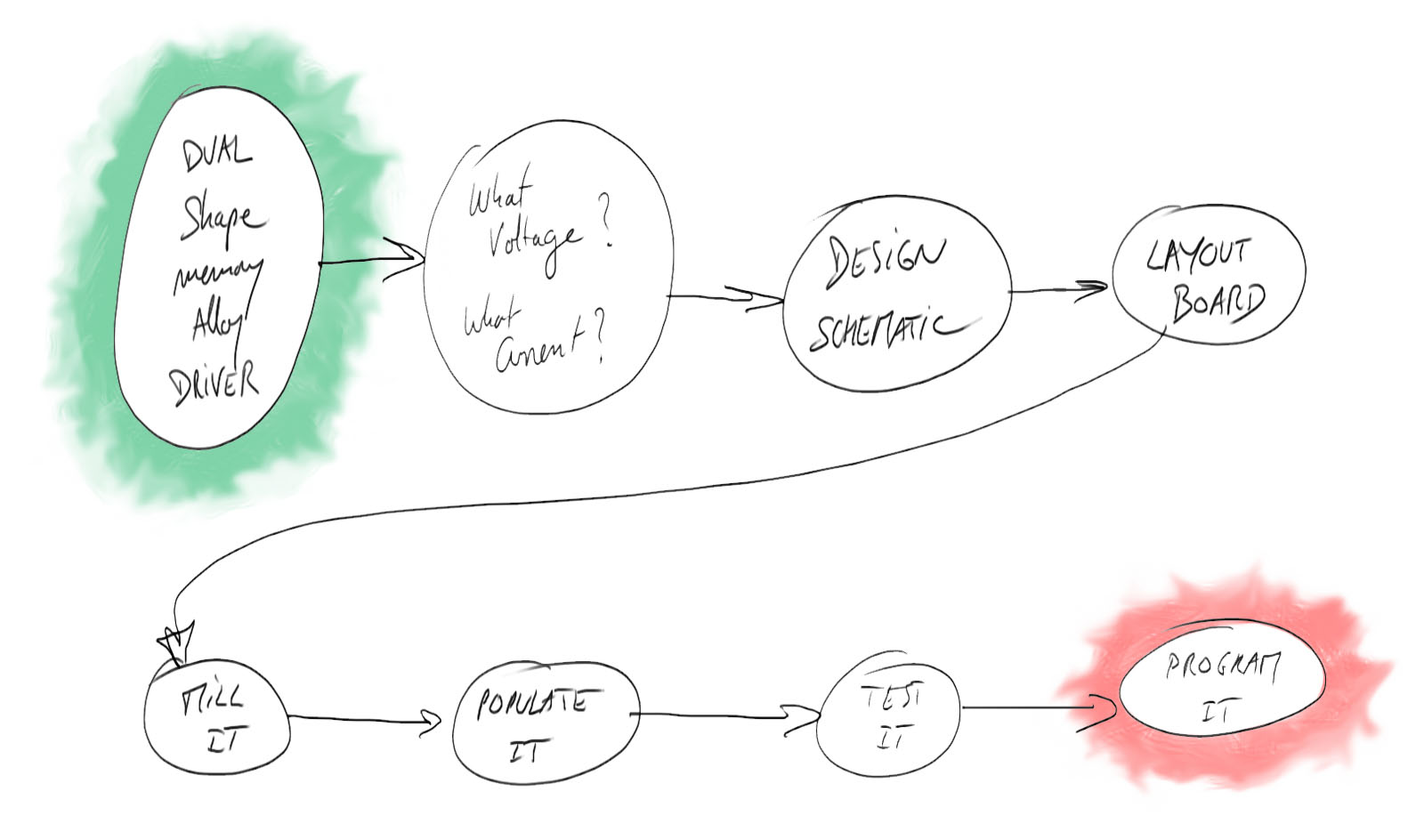
Flow chart for this week
Table of content :
STEPS
Drawing according to constraints
I will work on my final project for this assignment.
I need to create a driver board for the shape memory alloy wire (Nitinol) that I ordered from smartwires.eu
The idea is that when electricity goes through the wire, it heats it up, and when it reaches the activation temperature, the wire goes back to a previously set shape (annealing).
The amount of current that needs to goes through depends on different parameters that this chart illustrates :
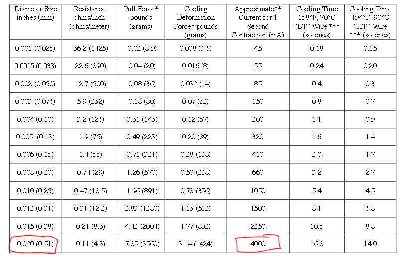
Activation and cooling time chart for different thicknesses
The most important thing is to avoid overheating the wire, otherwise it won't perform for thousands of cycles.
I will use 0.5 mm wires with activation temperature of 70°. According to the chart, 4A is recommended for 1 second contractions.
I don't need it to contract this fast and I want to play it safe first, so I'll use MOSFETS that can draw 1.7A, the one we were given the reference in the lecture.
Since I need nitinol that alternatively contract and expend, I will make a Dual driver (2 mosfets).
I also want to "see" when the current flows in the wire so I add LEDs for this.
Lastly, I want to have a button to start/stop it.
Drawing by hand a rough schematic helps going through a quick design process :
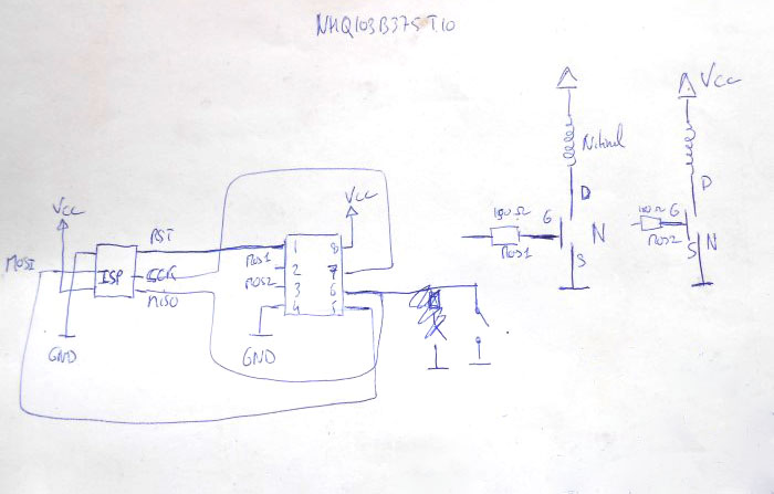
Hand drawing the schematic
Schematic
After defining the requirements and specifications, here is the schematic drawn in Eagle :
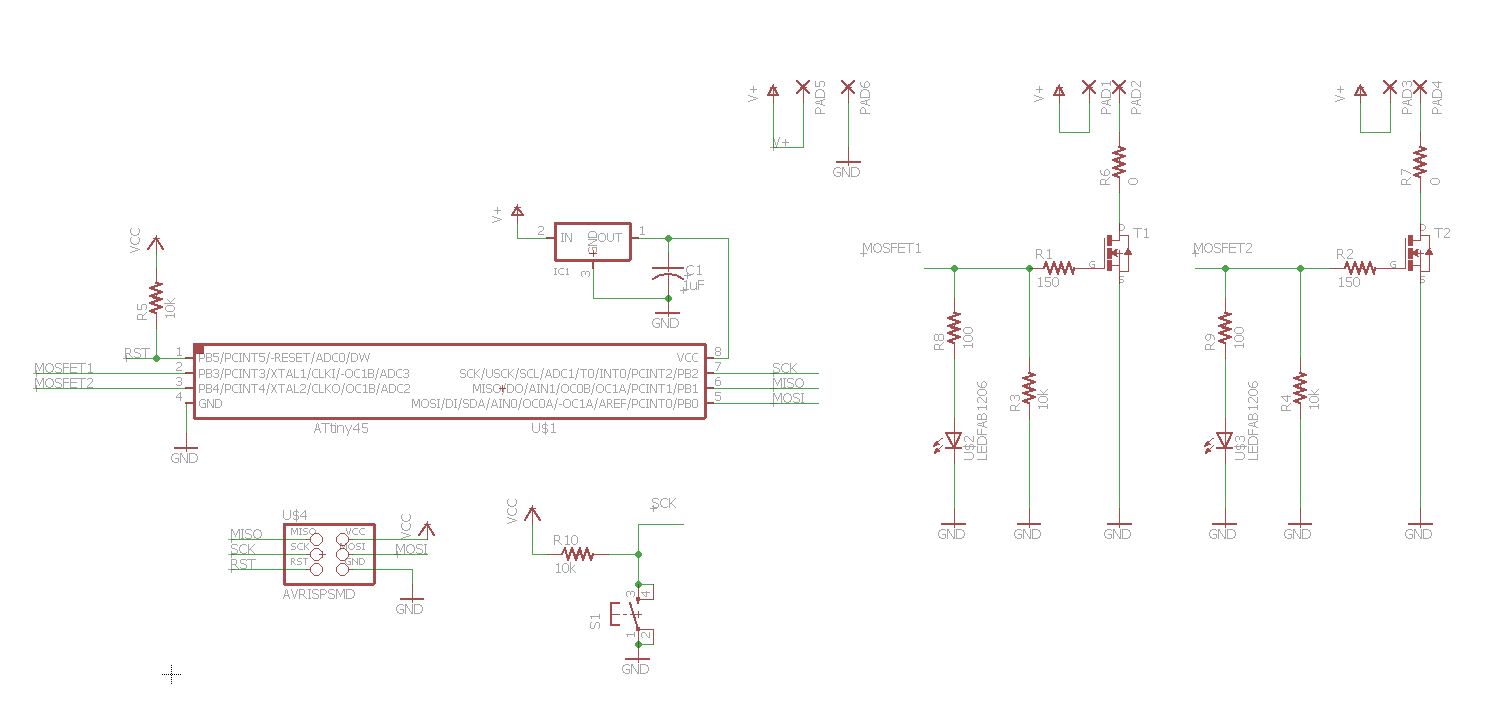
Schematic in Eagle
I added 0 ohm resistor in the nitinol circuits in case I need to limit the current going through them, then I would just replace them by appropriate resistors.
That can happen when the nitinol wires have to be powered with a voltage that's lower than the minimum voltage required for the board : 5V.
The resistors replacing the 0 ohm resistors should then be dimensioned to create the right voltage drop to match the desired voltage across the nitinol wire.
Layout
Here is the layout of the board done in Eagle :
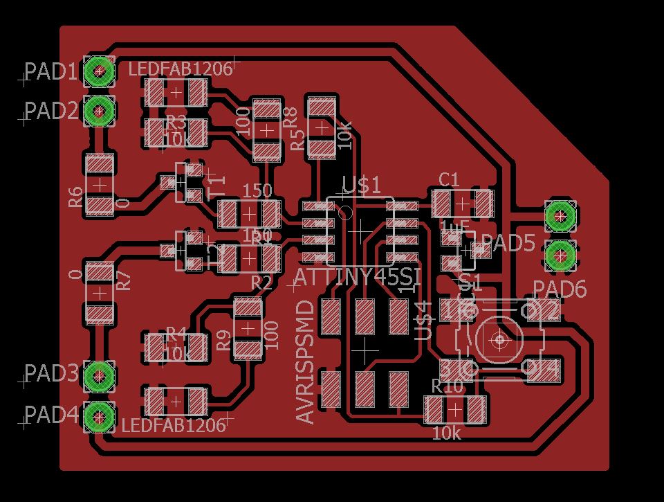
The dual Nitinol driver board
Since there is much more current passing through some traces I made them thicker.
I did through-hole connectors for easy connection with power and nitinol wire.
Making the board
The holes were a little too small for the connectors, so I used a little drill to widen them.
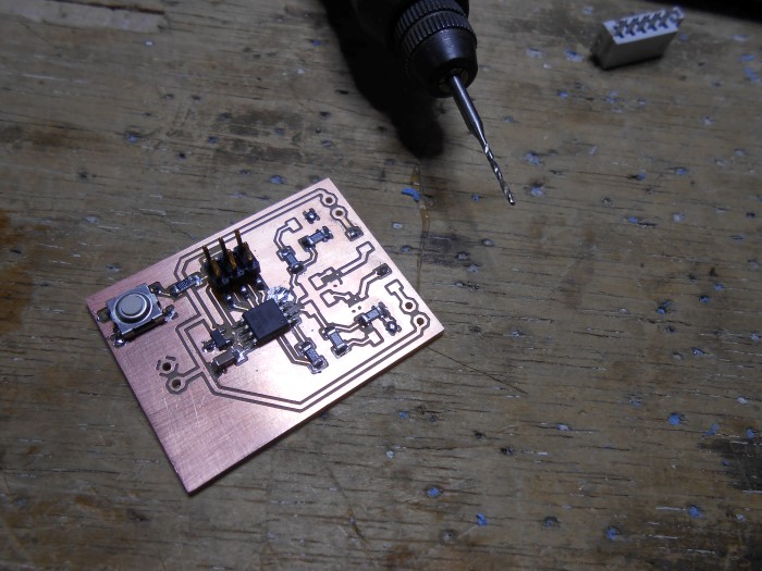
Hand widening the holes
Here is the board populated :

The dual Nitinol driver board populated
on the other side there is the connectors.
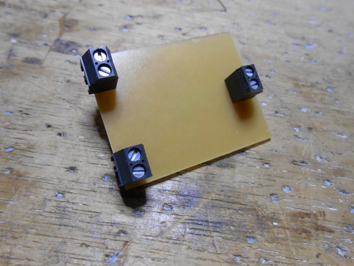
The connectors of the board
Programming
The programing is done on Ubuntu running on a virtual machine which this setup :
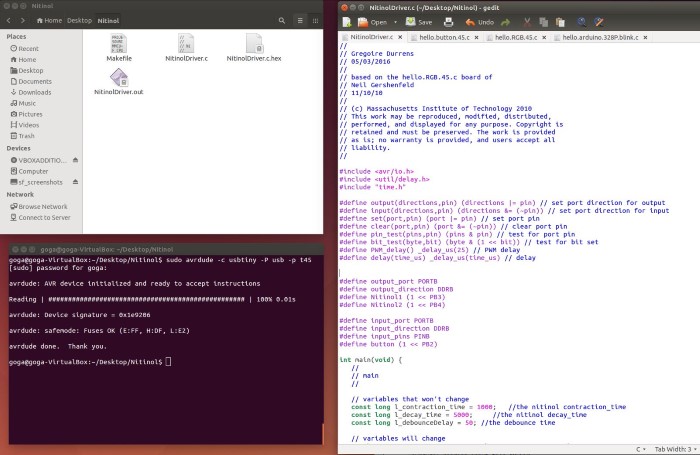
The usual set up on Ubuntu
To try that the connection is working, we just run this command to check we can indeed talk to the t45 chip.
sudo avrdude -p t45 -P usb -c usbtiny
I use the Arduino IDE to burn the fuses for internal 8Mhz clock :
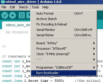
Burning the fuses with Arduino IDE
To start with I just quickly modify the RGB LED program. I don't use the Arduino IDE for programming, I use a text editor (gedit) and the avr-gcc compiler
I compile the program, upload it and check how it runs :
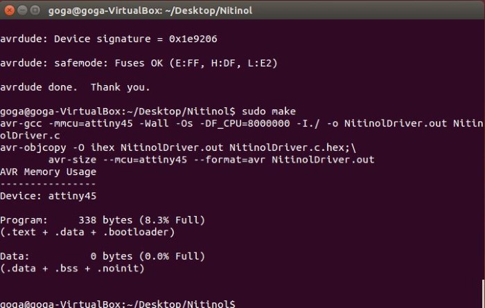
Compiling the C program
sudo make
sudo make program-usbtiny
Here it is in action :
LEDs showing the MOSFETs pulse width modulated output
I'm still working on the final dual driver program that will alternate the dual outputs and letting cooling time in between
Right now, I'm having an issue with including time.h to mimic the millis() function arduino IDE has. AVR-gcc compiler doesn't find the time.h file somehow.
Source files
Here are the sources files of the projects I talked about on this page :
Schematic - Eagle
Layout - Eagle
If you feel like contributing, please fork from Github :
Conclusion
***