Week 11
input devices
Assignment
- Measure something: add a sensor to a microcontroller board that you have designed and read it
Week workflow
Here is how I see the week's flow :

Flow chart for this week
Table of content :
STEPS
Concept
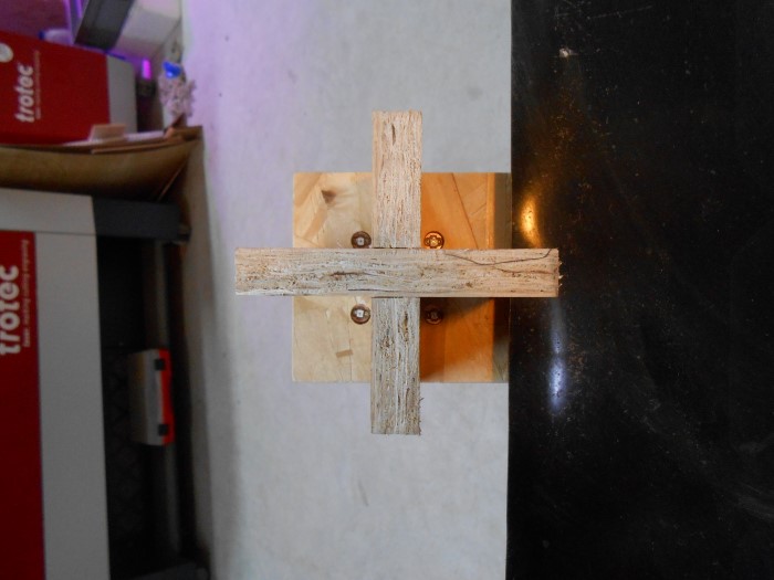
For the machine building assignment, we built a solar tracker.
Let's make the sensor board for it.
It consists of 4 light sensors separated by two orthogonal planes. Depending on how shadows from a light source cast on them, we can find out how we should move the planes to have no shadow cast on none of the sensors, hence align with the light source, here, the sun.
We can see how the tracking feature works in the following pictures :
![]()
The tracking feature in SolidWorks
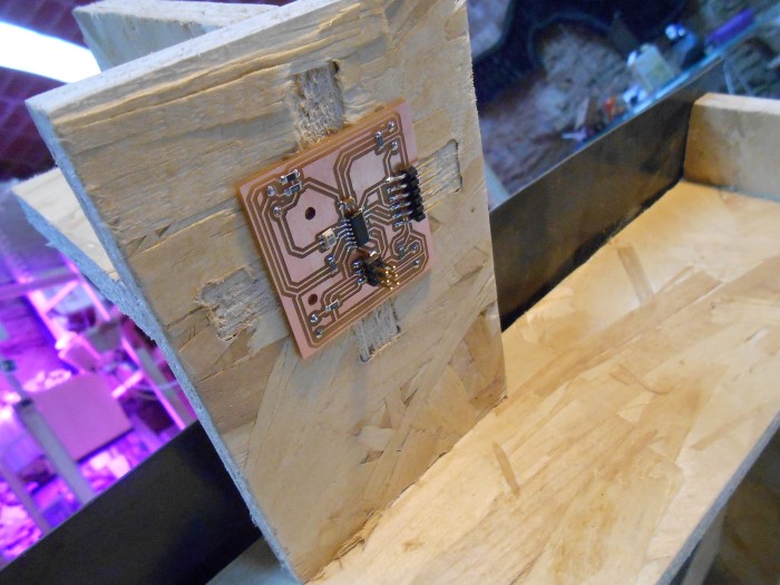
Here is the sensor feature in real :
![]()
The real tracking feature
The idea is to have the 4 light sensors in the 4 holes and the sensor board at the back :

Board position
The sensors are facing the other side of the main mcu board, and will stand off on tiny boards.

Sketch of the sensoring feature
Schematic
I start by designing the Schematic in Eagle. Check the week for "electronics design" for more details.
Like the one-sensor light sensor simple board that Neil Gershenfeld presents, I'm using pull-up resistors and photodarlington transistors but with a t44, not a t45, cause I have 4 inputs which is too many for the t45.
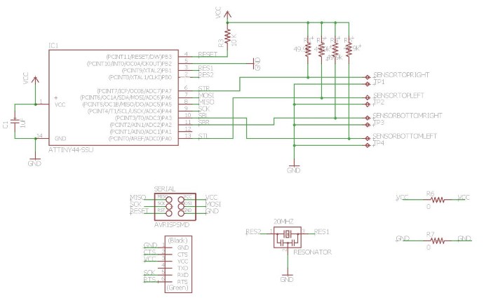
Schematic in Eagle
Board Layout
First I need to check for the exact position of my sensors.
Dimensions a and b are the useful ones :
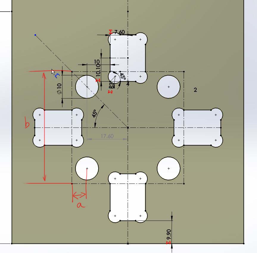
Positions of the sensors and dimensions
Then, still in Eagle, I layout my board according to the dimensions :
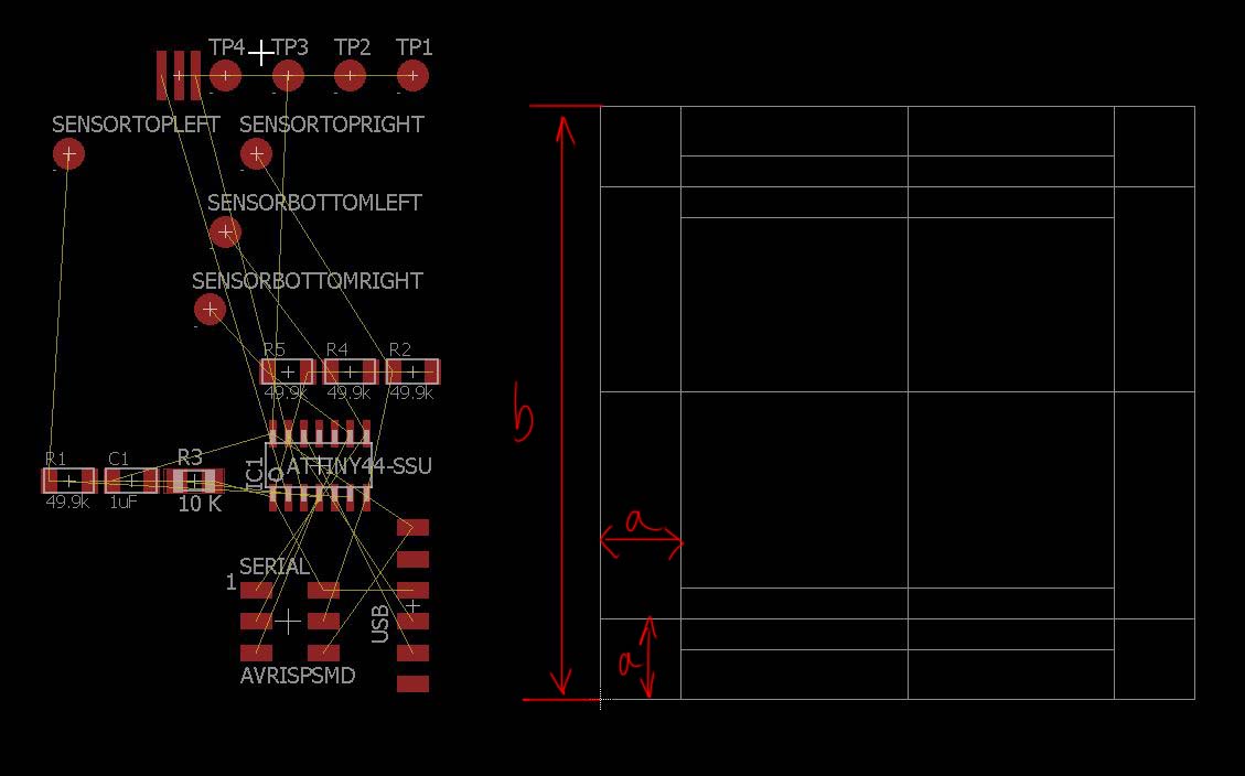
Laying out the PCB
I had to add two 0 Ohm resistors for the routing.
Here is the final Layout :
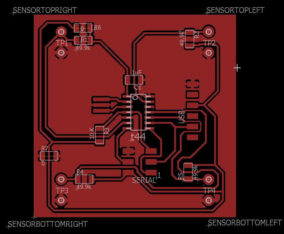
Board laid out
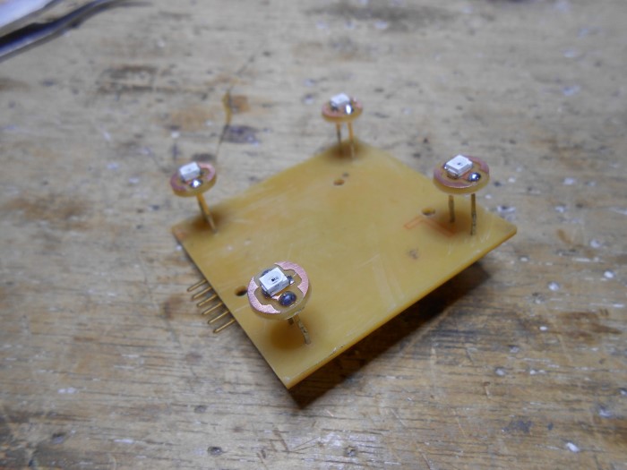
Now I need to do 4 tiny boards for the sensors.
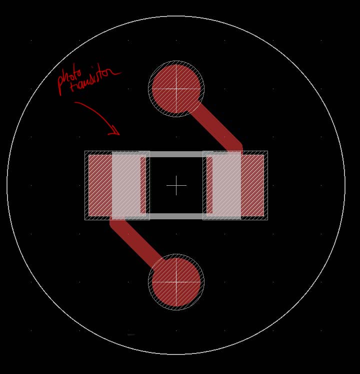
Tiny phototransistor board
Board manufacturing
With the Modella, I start milling the 4 tiny boards :
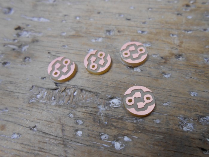
the small boards milled
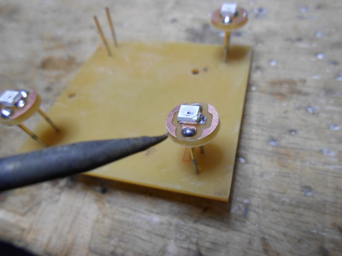
I solder the phototransistors :
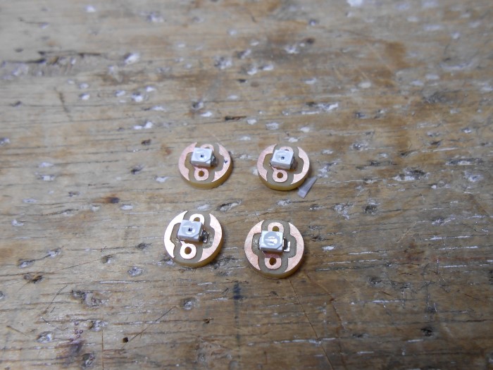
Soldering the phototransistors
Then I start populating the main board :
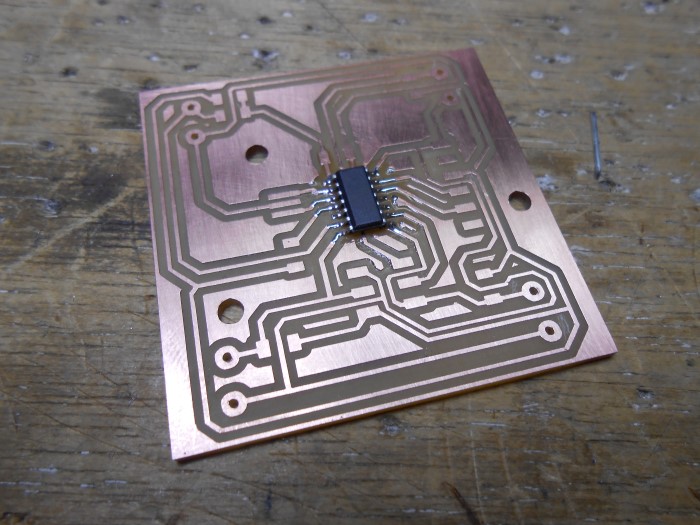
Populating the main sensor board
Here is the board populated :
It's slightly different from the eagle layout above cause this was the previous version (version 1 out of 2).
What changes is the mounting holes' position, an added 0 Ohm resistor, and slight different routing.
The look is the same though.

Board populated
To make the stand offs I'll use the pins of some connectors that I will straighten.

Straightening the pins
Then I solder the pins for the stand offs in the four corners:
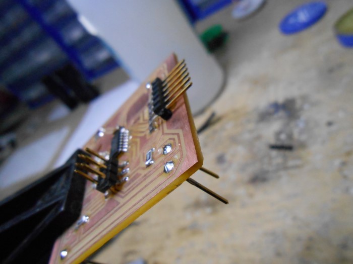
Soldering the pins
Once that's done, I solder my tiny light sensor boards :
Soldering the photoboards
And here is the complete device finished :
Device completed
In place in the tracker structure :
The light sensor in place
View from the bottom :
The light sensor in place - Bottom view
Each sensor in its corner :

One of the four sensors, in its corner
Programming
To upload programs via serial to our sensor board we'll use our FabISP that we made few weeks ago.
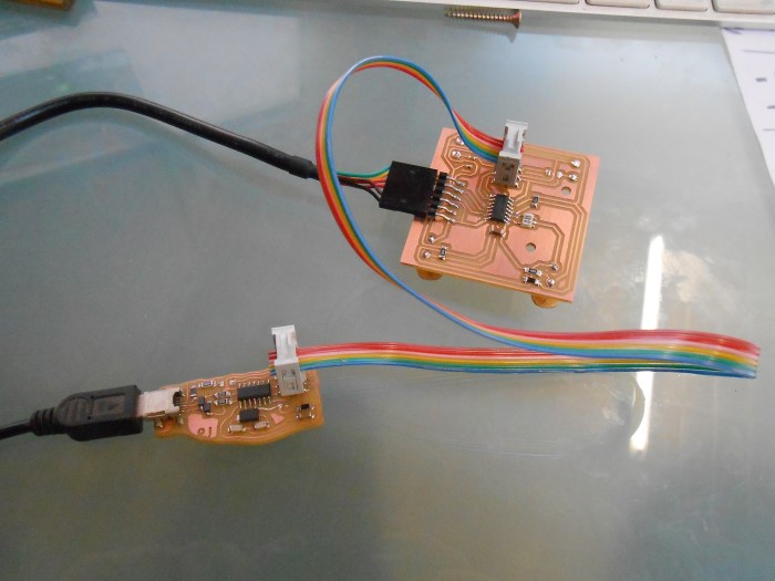
Setup for firmware upload
After having manufactured our board, let's make sure it talks alright to the computer.
We use Avrdude for this.
avrdude -c usbtiny -P usb -p t44
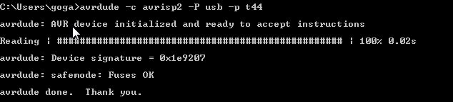
Checking the serial connection. In this picture we used another ISP the AVRISP mkII
Connection seems to be working fine so now we have to write our firmware that will be run on the MCU.
We have to modify/create two files : the firmware itself, solartracker.c, and the Makefile that compiles it and transfers it to the MCU.
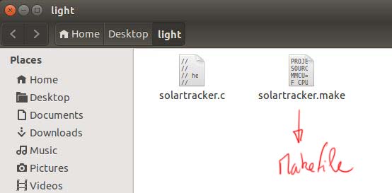
Files for the sensorboard
Let's modify the Makefile to fit our situation.
We modify the file provided on the fabacademy page for the light sensor.
We use a t44, not a t45, with an external clock at 20MHz.
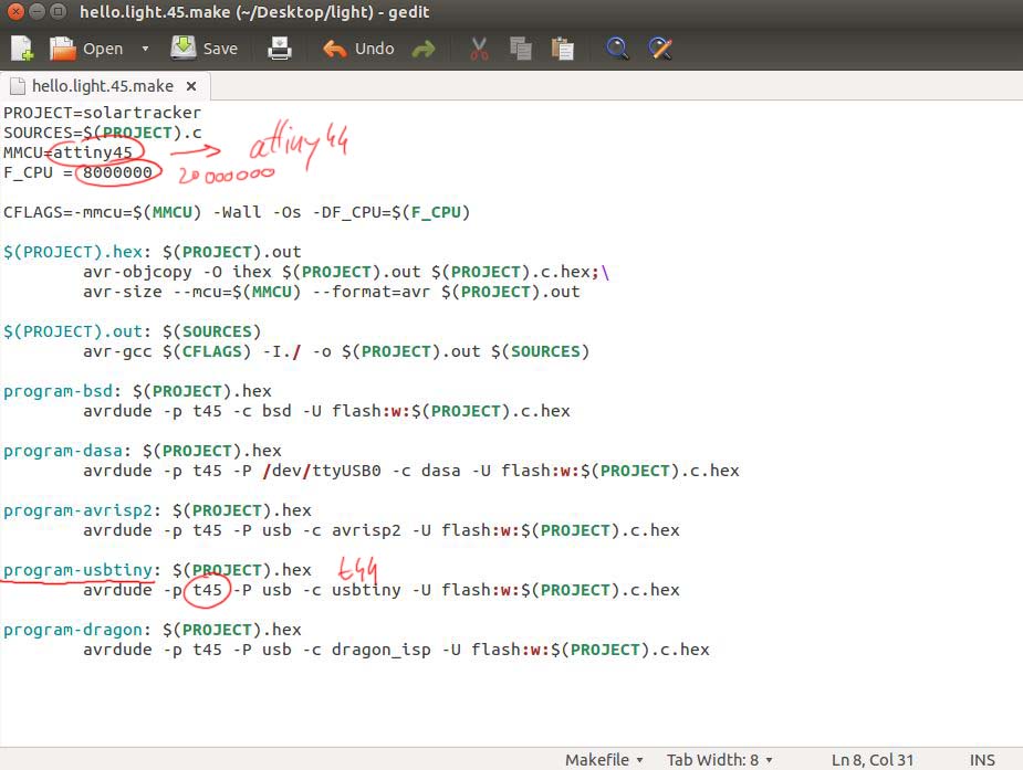
Adapting the Makefile
Then, we need to change the C program as well.
In the following section, I will explain what I did.
You can find the source here.
First, we set up the right port for serial communication, which is in our case the portA and the pin 4.

Setting up the Serial Port
After this, we need to change the setup of the ADC converter. The t44 registers that drive the ADC are not exactly the same as the t45.

ADC setup code modifications
All the information for this is contained in the t44 datasheet.
The register summary page is very useful :

The t44 datasheet register summary page
For example we need to change the REFS1 and REFS0 bits of the ADMUX register to use Vcc as the analog reference.
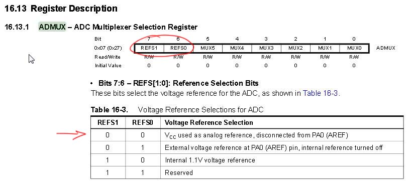
Setting Vcc as analog reference for ADC
When we make a reading on a pin that get signal from a sensors, we need to specify which pin it is.
Here, we have 4 sensors, so we're reading 4 signals, on 4 different pins, PA0 PA2 PA3 and PA7. I chose those pins during layout as they were easier to reach in the routing process.
So in our code, we'll read successively the 4 pins. We then have to write 4 successive times the MUX bits into the ADMUX register that will consequently select the right pins
This table gives us the bits combinations :
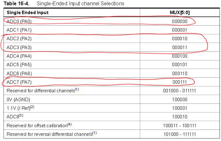
Input selection
Based on this table :

Single Ended conversion formula
Since we're using VCC as analog reference, we get a digital number between 0 and 1024 that represents the voltage between 0 and Vcc (USB 5V)
What we do next is that we find the barycenter of light intensity of the 4 sensors.
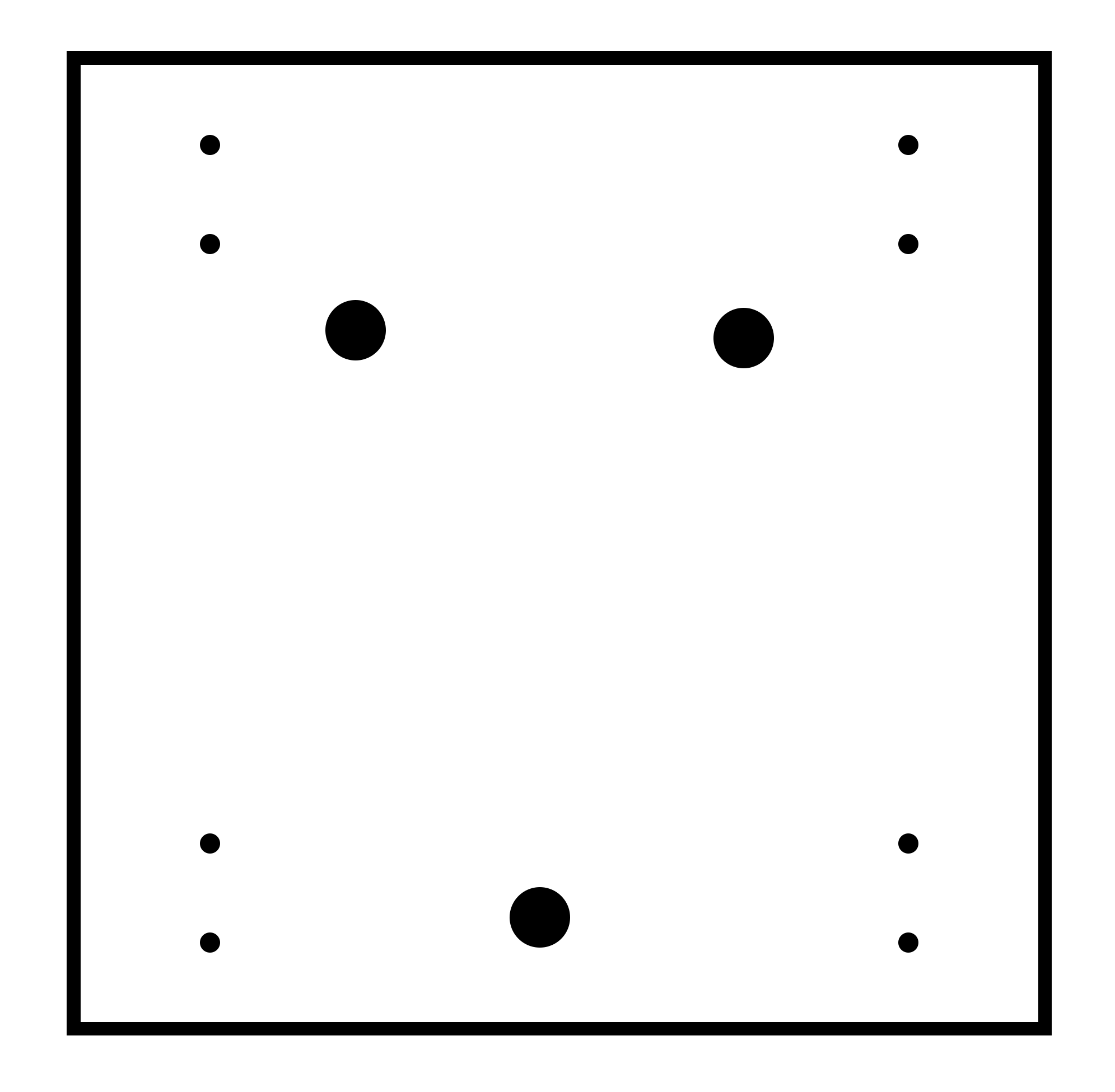
Based on the following drawing, we find the math that gives the coordinates of the barycenter in the 2D space where every corner represents a sensor :
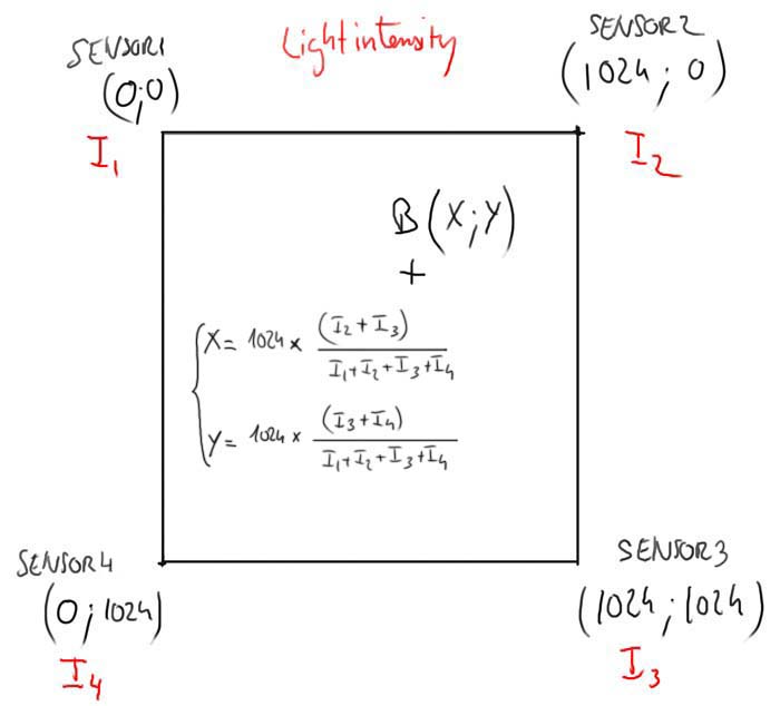
Light intensity barycenter coordinates
Then we send the barycenter coordinates over FTDI serial communication to the computer.
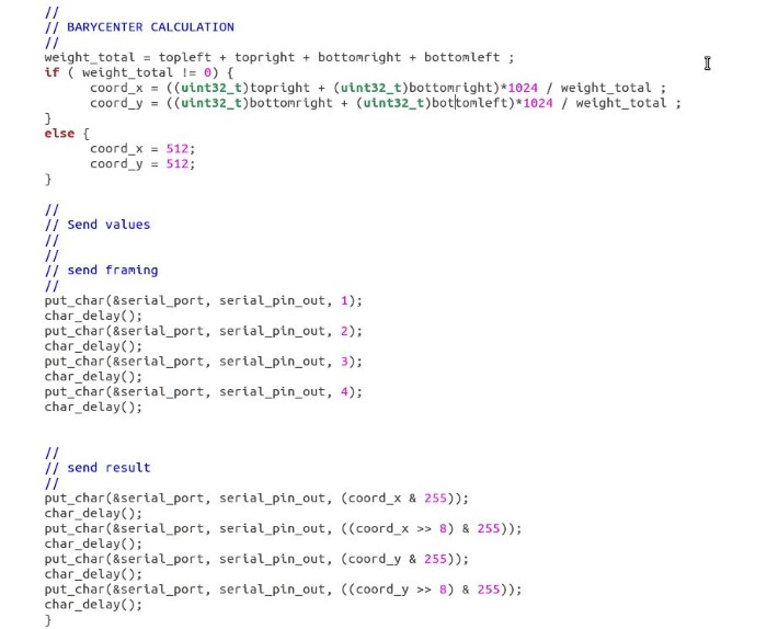
C implementation of the light intensity barycenter
Again, you can find the firmware C source code here.
Testing
Now we need to make the program that will receive the data from our board over FTDI on the computer.
Since we're doing a solar tracker, this program has vocation to receive data from the sensor, process it and then drive the motors of the tracker.
But for now, we'll just receive and process the data and show a representation of the incoming light direction showing the position of the barycenter we computed earlier.
I'm modifying the python program provided by the academy. It uses the Tkinter libraries for having a GUI object.
You can find the program here.
Here it is in action :
How the light direction shows on the screen
Source files
Here are the sources files of the projects I talked about on this page :
Solartracker.c - the firmware
Solartracker.py - the python program
Makefile - The makefile
Outline for the sensor board
Traces for the sensor board
Outline for the tiny phototransistor board
Traces for the tiny phototransistor board
Conclusion
***